Table of Contents
Advertisement
Quick Links
Advertisement
Table of Contents

Related Manuals for Powtran PI550 Series


Summary of Contents for Powtran PI550 Series
- Page 2 Thank you for choosing Powtran PI550 series high performance current vector frequency inverter. PI550 series high-performance current vector frequency inverter is a new generation of vector inverter developed by POWTRAN, which can be used to control asynchronous AC induction motors, use DSP control system, and strengthen product reliability and environmental adaptability, with more complete functions and applications.
-
Page 3: Table Of Contents
Contents Chapter 1 Inspection and safety precautions ..............1 1-1. Contents of this chapter ......................1 1-2. Security Definition .........................1 1-3. Warning sign ..........................1 1-4. Safety Guidance ........................1 Chapter 2 Quick Installation Guide ..................4 2-1. Contents of this chapter ......................4 2-2. - Page 4 4-11. Spare Circuit ........................55 Chapter 5 Keyboard ......................56 5-1. Contents ..........................56 5-2. Keyboard description ......................56 5-3. Keyboard operation ......................58 Chapter 6 Function parameter ..................60 6-1.Menu grouping ........................60 6-2.d0 Group - Monitoring function group .................61 6-3.F0 Group - Basic function group ..................62 6-4.F1 Group - Input terminals group ..................65 6-5.F2 Group - Output terminals group ..................
- Page 5 7-8. Application of multi-speed operation ................106 7-8-1 Electrical diagram: ....................106 7-8-2 Connection: .......................107 7-8-3 Parameter setting: ..................... 107 7-9. Application of external potentiometer for speed regulation ..........108 7-9-1 Electrical Diagram: ....................108 7-9-2 Connection: .......................108 7-9-3 Parameter setting: ..................... 108 7-10.
- Page 6 9-3. Power ..........................131 9-4. Cable Selection Guide ....................... 131 9-4-1 Power cables ........................131 9-4-2 Control Cable ......................132 9-5. Selection guidance of circuit breaker, electromagnetic contactor and leakage protection 132 9-6. Communication protocol ....................134 9-6-1. Communication content ..................... 134 9-6-2.
-
Page 8: Chapter 1 Inspection And Safety Precautions
Chapter 1 Inspection and safety precautions 1-1.Contents of this chapter This chapter mainly describes the precautions related to product handling, installation, operation, maintenance, disassembly and waste disposal. Safe operation depends on proper transportation, installation, operation, and maintenance. Failure to pay attention may result in system damage, personal injury, or even personal injury. - Page 9 Chapter 1.Inspection and safety precautions Type Explanation related operations. The waiting timetable is as follows, for reference, subject to the actual situation:: Inverter model At least wait time Voltage level 380V 0.75G-110G 5 minute Voltage level 380V 132G-315G 15 minute Voltage level 380V more than 315G 25 minute...
- Page 10 Chapter 1.Inspection and safety precautions Type Explanation marine, medical, aviation, nuclear power, etc. without permission. Unauthorized use environment may lead to fire, electric shock, explosion and other accidents.
-
Page 11: Chapter 2 Quick Installation Guide
●Determine whether the communication mode required by the inverter requires an external communication card. ●Do not change the three-phase inverter in the PI550 series to two-phase use, otherwise, the inverter will be damaged. ●The cooling fan of the ordinary three-phase asynchronous motor is coaxially connected to the rotor shaft, and the cooling effect of the fan is reduced when the speed is reduced. - Page 12 Chapter 2.Quick Installation Guide ●When the ambient temperature exceeds 40°C, please derate by 10% at 1°C. Please do not use the inverter in an environment above 50°C. ●In order to improve the reliability of the machine, use the inverter in a place where the temperature does not change rapidly.
-
Page 13: Installation And Wiring Confirmation
Chapter 2.Quick Installation Guide Allowable output current ( %) Ambient temperature (℃) Figure 2-1.PI550 series inverter over temperature derating curve Allowable output current (%) ●After exceeding the allowable altitude, use the derating as shown in the figure below. 2000 1000 3000 Altitude (m)... -
Page 14: Basic Debugging
Chapter 2.Quick Installation Guide inverter, it is not allowed to use this contactor to control the start and stop of the inverter. The contactor must be used to control the start and stop of the inverter, and the interval should not be less than one hour. Frequent charging and discharging will easily reduce the service life of the capacitors in the inverter. - Page 15 Chapter 2.Quick Installation Guide ●Adjust the acceleration and deceleration time according to the actual working conditions of the load. If there is no special requirement for the acceleration and deceleration time, the acceleration and deceleration time can be lengthened appropriately to reduce the current impact of the inverter. ●Jog the device to make sure that the motor direction is the same as the required direction.
-
Page 16: Chapter 3 Product Overview
DC voltage of the inverter bus remains within the normal voltage range. Figure 3-1.PI550 series & Main circuit diagram of 4kW and below Figure 3-2.PI550 series & Main circuit diagram of 37kW and above... -
Page 17: 3-3.Standard Specifications
Chapter 3.Product Overview 3-3.Standard specifications Items Specifications AC 1PH 220V(-15%)~240V(+10%) AC 3PH 220V(-15%)~240V(+10%) Rated voltage AC 3PH 380V(-15%)~440V(+10%) AC 3PH 480V(-10%)~480V(+10%) AC 3PH 690V(-10%)~690V(+10%) Input frequency 50Hz/60Hz Voltage continued Less than 3% of voltage unbalance rate 3%; volatility:±10% Allowing fluctuations Input frequency Distortion satisfy IEC61800-2 standard fluctuation:±5%;... - Page 18 Chapter 3.Product Overview Items Specifications Jog Ac/deceleration time: 0.0~6500.0s Multi-speed operation Achieve up to 16-speed operation through the control terminal Built-in PID Easy to realize closed-loop control system for the process control. Automatic voltage Automatically maintain a constant output voltage when the voltage of regulation(AVR) electricity grid changes "Excavator"...
- Page 19 Chapter 3.Product Overview Items Specifications multi-speed and serial port. They can be switched through a variety of ways. 8 digital input terminals, compatible with active PNP or NPN input Input terminals mode, one of them can be for high-speed pulse input(0~100 kHz square wave);...
- Page 20 Chapter 3.Product Overview Items Specifications The optional completely isolated RS485 communication module can RS485 communicate with the host computer. -10to 40℃ (The environment temperature in 40 ~ 50 ℃, please Environment temperature derating use) Storage temperature -20~65 ℃ Environment humidity Less than 90% R.H, no condensation.
-
Page 21: 3-4.Instructions On Nameplate
3-5.Model designation 045 G POWTRAN Inverter Code with DC reactance R:with DC reactor (don't write without DC reactance) Series Code Input Voltage Level PI550 Series 1:Single-phase 220V 2:Three-phase 220V 3:Three-phase 380V Rated output capacity 4:Three-phase 480V 045:45kW 6:Three-phase 690V 132:132kW Function code F:Light load... - Page 22 Chapter 3.Product Overview Adaptive Rated output Rated input Rated output Frame Model motor power(kW) current(A) current(A) power(kW) PI550 004G1 PI550 5R5G1 AC 3PH 220V(-15%)~240V(+10%) PI550 0R4G2 PI550 0R7G2 0.75 0.75 PI550 1R5G2 PI550 2R2G2 11.8 PI550 004G2 18.1 PI550 5R5G2 PI550 7R5G2 37.1 PI550 011G2...
- Page 23 Chapter 3.Product Overview Adaptive Rated output Rated input Rated output Frame Model motor power(kW) current(A) current(A) power(kW) PI550 7R5F3 20.5 PI550 7R5G3 20.5 PI550 011F3 PI550 011G3 PI550 015F3 PI550 015G3 PI550 018F3 18.5 38.5 18.5 PI550 018G3 18.5 38.5 18.5 PI550 022F3 46.5...
- Page 24 Chapter 3.Product Overview Adaptive Rated output Rated input Rated output Frame Model motor power(kW) current(A) current(A) power(kW) PI550 200F3 PI550 200G3 PI550 220F3 PI550 220G3 PI550 250F3 PI550 250G3 PI550 280F3 PI550 280G3 PI550 315F3 PI550 315G3 PI550 355F3 PI550 355G3 PI550 400F3 PI550 400G3 PI550 450F3...
- Page 25 Chapter 3.Product Overview Adaptive Rated output Rated input Rated output Frame Model motor power(kW) current(A) current(A) power(kW) PI550 022F4 41.7 PI550 022G4 41.7 PI550 030F4 57.4 PI550 030G4 57.4 PI550 037F4 66.5 PI550 037G4 66.5 PI550 045F4 81.7 PI550 045G4 81.7 PI550 055F4 101.9...
- Page 26 Chapter 3.Product Overview Adaptive Rated output Rated input Rated output Frame Model motor power(kW) current(A) current(A) power(kW) PI550 315F4 533.2 PI550 315G4 533.2 PI550 355F4 623.3 PI550 355G4 623.3 PI550 400F4 706.9 PI550 400G4 706.9 PI550 450F4 PI550 450G4 AC 3PH 690V±10% PI550 011G6/015F6 11/15 15/20...
-
Page 27: 3-7.Special Customized Product Specifications
Chapter 3.Product Overview Note: (1)PI550 frequency converter PI550 132G3 / PI550 160F3 ~ PI550 630G3 with "R" indicates DC reactor, such as PI550 160G3R,PI550 160G4R. (2) The correct selection method of frequency converter is: the rated output current of frequency converter is greater than or equal to the rated current of motor, and the overload capacity is considered;... -
Page 28: Chapter 4 Installation And Commissioning
The correct grounding method is shown in the following figure: Figure 4-1. PI550 series frequency inverter Multiple parallel grounding Figure 4-2. PI550 series inverter system grounding Note: the motor must be grounded nearby and independently, Do not connect the motor casing to... -
Page 29: Generation And Treatment Of Leakage Current
Chapter 4.Installation and commissioning 4-3.Generation and treatment of leakage current There are two forms of leakage current when using the frequency converter: one is the leakage current to the ground; the other is the leakage current between lines. ● factors affecting the ground leakage current and solutions: There is distributed capacitance between the conductor and the earth. -
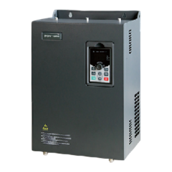
Page 30: Product Structure Diagram
Chapter 4.Installation and commissioning 4-5.Product structure diagram The following figure shows the layout of the frequency converter (taking the plastic shell PI550G3 4kw as an example) Figure 4-3. plastic shell structure diagram Name Explanation keypad interface for connecting keypad Upper cover plate Protect internal components Keyboard See "keyboard operation instructions"... - Page 31 Chapter 4.Installation and commissioning The following figure shows the layout of the frequency converter (taking the metal shell PI550G3 93- 110kw as an example) Figure 4-4. Metal shell structure diagram Name Explanation Logo Company logo Keyboard See "keyboard operation instructions" for details Upper cover plate Protect internal components Keyboard compartment...
-
Page 32: Installation Direction And Space
Figure 4-6. PI550 Series Each power level installation space requirement Note: PI550 Series frequency inverter heat radiator circulated from bottom to top, when more than one inverter work together, usually mounted side by side. In the case of the need to install them by upper and... -
Page 33: Installation Method
Figure 4-7. Heat insulation deflector up and down installation diagram 4-7.Installation method PI550 series frequency inverter can be installed in four ways according to its structure: Guide rail installation (applicable to frame No.: A1 ~ A2) Wall mounted installation (applicable to frame No.: A1 ~ A14) Flange installation (for A5 ~ A12 iron shell, flange installation accessories shall be selected). -
Page 34: Product Outline Dimension And Installation Dimension
Chapter 4.Installation and commissioning 4-8.Product outline dimension and installation dimension 4-8-1. Shell molding machine series Note: frame No.: A1 ~ A2 support Guide rail installation Figure 4-8. 0.4~4kW G3 outline dimension(Frame No.:A1~A2) Figure 4-9. 5.5~11kW G3 outline dimension(Frame No.:A3)... - Page 35 Chapter 4.Installation and commissioning Figure 4-10. 15~22kW G3 outline dimension(Frame No.:A4) Single phase AC220V series outline dimension drawing and installation dimension Guide rail Installation Output Dimension(mm) installation Weight Frame Model power (mm) position (kg) (kW) H H1 W PI550 0R4G1 163 185 90 146 154 72.5 PI550 0R7G1...
- Page 36 Chapter 4.Installation and commissioning Three AC220V series outline dimension drawing and installation dimension Guide rail Installation Output Dimension(mm) installation Weight Frame Model power (mm) position (kg) (kW) H H1 W PI550 0R4G2 PI550 0R7G2 0.75 163 185 90 146 154 65 174 5 72.5 PI550 1R5G2 PI550 2R2G2...
-
Page 37: 4-8-2.Iron Shell Wall Hanging Series
Chapter 4.Installation and commissioning Three phase 480VAC outline dimension drawing and installation dimension Guide rail Output Dimension Installation installation Weight Frame (mm) (mm) Model power position (kg) (kW) H H1 W D D1 PI550 0R7G4 0.75 163 185 90 146 154 65 174 5 72.5 PI550 1R5G4 PI550 2R2G4... - Page 38 Chapter 4.Installation and commissioning Figure 4-12. 250~400kW G3 Dimension(Frame No.:A12~A13) Outline dimension drawing and installation dimension of single phase 220VAC Installation Dimension (mm) Output power Weight Frame (mm) Model (kW) (kg) H H1 W D D1 PI550 011G1 330 350 210 190 198 150 335 Outline dimension drawing and installation dimension of three phase 220VAC Installation Dimension (mm)
- Page 39 Chapter 4.Installation and commissioning Three phase 380VAC outline dimension drawing and installation dimension Dimension Installation Weight Frame (mm) (mm) Model Output power (kW) (kg) H H1 W D D1 A PI550 030F3 330 350 210 190 198 150 335 6 PI550 030G3 PI550 037F3 PI550 037G3...
- Page 40 Chapter 4.Installation and commissioning Dimension Installation Weight Frame (mm) (mm) Model Output power (kW) (kg) H H1 W D D1 A PI550 400F3 PI550 400G3 940 980 705 410 418 550 945 13 PI550 450F3 PI550 450G3 Three phase 480VAC outline dimension drawing and installation dimension Dimension Installation Weight...
- Page 41 Chapter 4.Installation and commissioning Dimension Installation Weight Frame (mm) (mm) Model Output power (kW) (kg) H H1 W D D1 A PI550 250F4 PI550 250G4 940 980 560 410 418 415 945 13 PI550 280F4 PI550 280G4 PI550 315F4 PI550 315G4 PI550 355F4 PI550 355G4 940 980 705 410 418 550 945 13...
-
Page 42: 4-8-3.Specification And Type Of Special Customized Product
Chapter 4.Installation and commissioning Dimension Installation Weight Frame (mm) (mm) Model Output power (kW) (kg) H H1 W D D1 A PI550 220G6/250F6 220/250 PI550 250G6/280F6 250/280 PI550 280G6/315F6 280/315 PI550 315G6/355F6 315/355 940 980 705 410 418 550 945 13 PI550 355G6/400F6 355/400 PI550 400G6/450F6... - Page 43 Chapter 4.Installation and commissioning Figure 4-13. 132~220kW G3R (Frame No.:A14~A15) Figure 4-14. 250~400kW G3R (Frame No.:A16~A17)...
- Page 44 Chapter 4.Installation and commissioning Outline dimension drawing and installation dimension of three phase 380VAC & three phase 480VAC Dimension Installation Output power Weight Frame (mm) (mm) Model (kW) (kg) H1 W D D1 A PI550 132G3R/160F3R 132/160 995 1020 400 360 368 350 270 13*18 PI550 132G4R/160F4R PI550 160G3R/187F3R 160/187...
- Page 45 Chapter 4.Installation and commissioning Figure 4-15. 450~630kW G3R(Frame No.:A18) Outline dimension drawing and installation dimension of three phase 380VAC Installation Dimension (mm) Output power Weight Frame (mm) Model (kW) (kg) PI550 500F3R PI550 500G3R/560F3R 500/560 1700 1200 600 612 680 550 PI550 560G3R/630F3R 560/630 PI550 630G3R/710F3R...
-
Page 46: 4-8-5.Pi550 Keypad Dimension Drawing
Chapter 4.Installation and commissioning 4-8-5.PI550 Keypad dimension drawing PI550 keyboard size (Size:mm) Figure 4-16. 5- ? 4.2 90°... - Page 47 Chapter 4.Installation and commissioning Keyboard size chart (Size:mm) Figure 4-17. Opening size of Opening panel 126.5*82 external mounting panel T=1.0~1.5mm mounting panel 82±0.2 Keyboard installation opening size chart (Size:mm) Figure 4-18. Notes: 1.The keyboard compartment is installed on the panel of the inverter with square hole, the hole size mm(82±0.2)*(126.5±0.2);...
-
Page 48: Main Circuit Terminal
Chapter 4.Installation and commissioning 4-9.Main circuit terminal 4-9-1.Main circuit terminal arrangement 1) 0.75~4kW G3 main circuit terminal (plastic shell) 68.6 M3 Combination screw RB - Figure 4-19. 0.75~4kW G3 main circuit terminal(Frame No.:A1~A2) main circuit terminal ( plastic shell ) 2) 5.5~11kW G3 M4 Combination screw M4 Combination screw... - Page 49 Chapter 4.Installation and commissioning main circuit terminal 4) 30kW G3/F3 M5 Combination screw M5 Combination screw 180.5 Figure 4-22. 30kW G3/F3main circuit terminal(Frame No.:A5) main circuit terminal 5) 37~45kW G3/F3 10.5 M6 Combination screw M5 Combination screw Figure 4-23. 37~45kW G3/F3main circuit terminal(Frame No.:A6) main circuit terminal 6) 37~55kW G3B&055G3/F3 10.5...
- Page 50 Chapter 4.Installation and commissioning Figure 4-24. 37~55kW G3B&055G3/F3main circuit terminal(Frame No.:A7) main circuit terminal 7) 75kW G3B M8 Combination screw M6 Combination screw Figure 4-25. 75kW G3Bmain circuit terminal(Frame No.:A19) 8) 75kW G3/F3 main circuit terminal M8 Combination screw M6 Combination screw Figure 4-26.
- Page 51 Chapter 4.Installation and commissioning Figure 4-27. 93~132kW G3/F3 main circuit terminal(Frame No.: A9) main circuit terminal 10) 160kW G3/F3 68.4 33.4 M10 Flat pad+Spring washer+Nut Figure 4-28. 160kW G3/F3 main circuit terminal(Frame No.:A10) main circuit terminal 11) 187~220kW G3/F3 68.4 33.4 M10 Flat pad+Spring washer+Nut Figure 4-29.
-
Page 52: Function Description Of Main Circuit Terminal
Chapter 4.Installation and commissioning M12 Flat pad+Spring washer+Nut 105 205 Figure 4-30. 250~450kW G3/F3 main circuit terminal(Frame No.:A12~A13) main circuit terminal 13) 500~630kW G3R 42.5 42.5 119.5 119.5 80 39.5 M12 Flat pad+Spring washer+Nut Figure 4-31. 500~630kW G3R main circuit terminal(Frame No.:A18) Note: P/+ standard configuration is short circuit ;... -
Page 53: Precautions For Main Circuit Terminal Wiring
Chapter 4.Installation and commissioning Output terminals Connect to three-phase motor U、V、W DC bus output terminals Connect to braking unit +,- Connect to DC reactor(Remove the shorting block) DC reactor terminals P,+ 4-9-3.Precautions for main circuit terminal wiring ●The main circuit terminal wiring must be firm and reliable. Loose wiring will cause damage to the inverter and peripheral equipment. -
Page 54: Varistor And Safety Capacitor Switch
Chapter 4.Installation and commissioning in accordance with the relevant provisions of the national electrical regulations. 4-9-4. Varistor and safety capacitor switch For the power grid system with the neutral point grounded, the customer needs to close the varistor switch (VDR) and the safety capacitor switch (EMC) by themselves (that is, press the switch "1"); If it is used in an IT power grid system (neutral point-to-ground insulation or high-impedance grounding), both the varistor (VDR) grounding switch and the safety capacitor (EMC) grounding switch need to be disconnected, as shown in the figure below (“0”... -
Page 55: Control Circuit Terminals
Chapter 4.Installation and commissioning 4-10.Control circuit terminals 4-10-1.control circuit terminals arrangement control panel control circuit terminals Figure 4-34. KZ12 Control panel control circuit terminals 4-10-2.Description of control circuit terminals Category Symbol Name Function Output +10V power supply, maximum output current: 10mA +10V- +10V power Generally it is used as power supply of external... - Page 56 Chapter 4.Installation and commissioning Category Symbol Name Function terminal 2 on the selected AI2 jumper on control panel. 2.Input impedance: 20kΩ with voltage input, 250Ω with current input. 1, Input range:DC-10~+10V Analog input 2, Voltage input impedance:20kΩ; terminal 3 3.AI3 reference potential can be GND or -10V. Multi-function digital input 1 Multi-function...
- Page 57 Chapter 4.Installation and commissioning Category Symbol Name Function TA1-TC1 Normally open Contactor drive capacity: Normally closed TA2-TC2 terminals Relay contact 3A/AC 250V,normally open contact 5 output Normally A/AC 250V, COSø = 0.4. TB1-TC1 closed terminals PT100 temperature senso. Note: Such as PT100 Motor three detection line, with a universal table test, to temperature...
-
Page 58: Wiring Diagram
Chapter 4.Installation and commissioning 4-10-3.wiring diagram The inverter wiring is divided into two parts: the main circuit and the control circuit. Be sure to connect correctly according to the wiring circuit shown in the figure below. The following figure shows the wiring diagram of KZ12 control boards: Main circuit Control circuit Figure 4-35. - Page 59 Chapter 4.Installation and commissioning The location of the jumper on the KZ12 control boards is shown below: Figure 4-36. The location of the jumper on the KZ12 control board...
-
Page 60: Signal Input Terminal Wiring Diagram
Chapter 4.Installation and commissioning 4-10-4.Signal input terminal wiring diagram The switching input and output signals are generally transmitted by shielded cables, and the wiring distance is as short as possible. The shielding layer is well grounded on the side which close to the inverter, and the transmission distance should not exceed 20m. -
Page 61: Control Terminal Wiring Precautions
Chapter 4.Installation and commissioning External Inverter Inverter External controller controller Shielded cable (Default) Shielded +24V +24V (Default) External cable power supply Inner power supply NPN External power supply NPN connect mode connect mode Figure 4-38. Signal input terminal circuit - Open collector NPN wiring Note: When using an external power supply, the jumper caps of the PLC and 24V must be removed, otherwise the product will be damaged. -
Page 62: Spare Circuit
Chapter 4.Installation and commissioning strong current lines (such as power lines, motor lines, relay connecting lines or contactor), and should not be placed in parallel with the strong current lines. , it is recommended to use vertical wiring to prevent the inverter from malfunctioning due to interference. -
Page 63: Chapter 5 Keyboard
Chapter 5 Keyboard 5-1.Contents This chapter introduces the operation of the keys, indicator lights and display of the keyboard; it also introduces the method of using the keyboard to view and set function parameters. 5-2.Keyboard description ●Keyboard structure Figure 5-1:operation panel display ●Keyboard Indicators Indicator Name... - Page 64 Chapter 5.Keyboard * Quick flashing: in the fault status frequency unit current unit Units voltage unit combination HzAV speed unit indicato percentage ●Description of operation panel keys Function Sign Name * Enter into the modified status of main menu Parameter * Esc from functional parameter modification Setting/Esc Key * Esc submenu or functional menu to status menu...
-
Page 65: Keyboard Operation
Chapter 5.Keyboard ●Keyboard display letters and numbers correspondence table Corresponding Display Corresponding Display Corresponding Display letters letters letters letters letters letters Digital display area Keyboard cable extension ability: for better environment, the keyboard cable impedance is small, which can generally be extended by about 100m. For field applications in special environments, you can consult our service engineers, who will serve you wholeheartedly. - Page 66 Chapter 5.Keyboard Description: Back to the level 2 menu from level 3 menu by PRG key or ENTER key in the level 3 operation status. The differences between the two keys : ENTER will be back to the level 2 menu and save parameter setting before back, and transfer to the next function code automatically;...
-
Page 67: Chapter 6 Function Parameter
, d group is the monitoring function parameters. In the PI550 series inverter, some parameters are "undefined by the manufacturer". For the parameters undescribed in the manual, please do not try to modify them to avoid errors. -
Page 68: 6-2.D0 Group - Monitoring Function Group
Chapter 6.Function parameter AI、DA calibration Linearity accuracy correction Motor parameters To set motor parameter To set password, parameter initialization and parameter Function code management group display Fault query Fault message query 6-2. d0 Group - Monitoring function group Factory Code Parameter name Setting range setting... -
Page 69: 6-3.F0 Group - Basic Function Group
Chapter 6.Function parameter value communication port Encoder feedback d0.26 PG feedback speed, to an accuracy of 0.01Hz 0.01Hz speed Master frequency d0.27 Frequency set by F0.03 master frequency setting source 0.01Hz display Auxiliary frequency d0.28 Frequency set by F0.04 auxiliary frequency setting source 0.01Hz display Observe the set command torque under the torque control... - Page 70 Chapter 6.Function parameter memory when power off ) 2: Analog AI1 setting 3: Analog AI2 setting 4: Panel potentiometer setting 5: High speed pulse setting 6: Multi-speed running setting 7: Simple PLC program setting 8: PID control setting 9: Remote communication setting 10: Analog quantity AI3 setting Frequency source F0.04...
- Page 71 Chapter 6.Function parameter 7: Simple PLC setting 8: PID setting 9: Communication given Tens digit: Terminal command binding frequency source selection (0 ~ 9, same as units digit) Hundreds digit: Communication command binding frequency source selection (0 ~ 9, same as units digit) Depends ☆...
-
Page 72: 6-4.F1 Group - Input Terminals Group
Chapter 6.Function parameter 6-4. F1 Group - Input terminals group Factory Code Parameter name Setting range Change setting ★ F1.00 DI1 terminal function selection ★ F1.01 DI2 terminal function selection F1.02 DI3 terminal function selection ★ F1.03 DI4 terminal function selection ★... - Page 73 Chapter 6.Function parameter The function of digital multifunction input terminal DI1-DI8 (DI5 can be used as a high-speed pulse input terminal), can be set by parameter F1.00-F1.07, and the optional function is shown in the following table: Setting Function Description value The terminal for not use can be set to "no function"...
- Page 74 Chapter 6.Function parameter Corresponding Command setting parameters 0 -stage speed setting 0X E1.00 1 -stage speed setting 1X E1.01 2 -stage speed setting 2X E1.02 3 -stage speed setting 3X E1.03 4 -stage speed setting 4X E1.04 5 -stage speed setting 5X E1.05 6 -stage speed setting 6X E1.06...
- Page 75 Chapter 6.Function parameter When the frequency reference is the digital frequency, this UP/DOWN setting terminal is used to clear the changed frequency value by (Terminal, keyboard) terminal UP/DOWN or keyboard UP/DOWN, so that the reference frequency can recover to the set value of F0.01. When the command source is set to the terminal control (F0.11 = 1), the terminal can be used to switch between Run command switch...
- Page 76 Chapter 6.Function parameter adjustments of PID are still valid. Switch between frequency source When the terminal is active, the frequency source A is master setting and replaced by the preset frequency (F0.01) preset frequency Switch between frequency source When the terminal is active, the frequency source B is auxiliary setting and replaced with the preset frequency (F0.01) preset frequency...
- Page 77 Chapter 6.Function parameter F1.14 Maximum input for AIC1 F1.12 ~+10.00V 10.00V ☆ F1.14 corresponding F1.15 -100.0% ~+100.0% 100.0% ☆ setting F1.16 Minimum input for AIC2 0.00V ~F1.18 0.00V ☆ F1.16 corresponding ☆ F1.17 -100.0% ~+100.0% 0.0% setting F1.18 Maximum input for AIC2 F1.16 ~+10.00V 10.00V ☆...
-
Page 78: 6-5.F2 Group - Output Terminals Group
Chapter 6.Function parameter Tens digit: DI2 Hundreds digit: DI3 Thousands digit: DI4 Ten thousands digit: DI5 Units digit: DI6 0: High level active; 1: Low level active DI terminal valid mode Tens digit: DI7 ★ F1.36 00000 selection 2 Hundreds digit: DI8 Thousands digit: DI9 Ten thousands digit: DI10 F1.37 DI1 delay time... - Page 79 Chapter 6.Function parameter F2.02 Relay 1 output function selection (TA1.TB1.TC1) ☆ F2.03 Undefined SPA output function selection (Collector open ☆ F2.04 circuit output terminals) ☆ F2.05 Relay 2 output function selection (TA2.TC2) The above 5 function codesare used to select the functions of five digital outputs . The function description of the multi-function output terminal is as follows: Setting Functions...
- Page 80 Chapter 6.Function parameter has not detected any fault information, and the inverter is in a runnable state, output ON signal. When the value of the analog input AI is greater than the AI1>AI2 value of AI2 input, output ON signal. When the running frequency reaches the upper frequency, Upper frequency arrival output ON signal.
- Page 81 Chapter 6.Function parameter Current running time When the inverter running time is longer than the time set arrival by F7.45, output ON signal. Undefined SPB high-speed pulse output function ☆ F2.06 selection 0~17 F2.07 DA1 output function selection ☆ F2.08 DA2 output function selection ☆...
-
Page 82: 6-6.F3 Group - Start And Stop Control Group
Chapter 6.Function parameter Units digit: SPB switching quantity 0: Positive logic; 1: Anti-logic DO output terminal active F2.15 Tens digit: Relay 1 00000 ☆ status selection Hundreds digit: reserved Thousands digit: SPA Ten thousands digit: Relay 2 F2.16 DA1 zero bias coefficient -100.0% ~ +100.0% 0.0% ☆... -
Page 83: 6-7.F4 Group - V/F Control Parameters
Chapter 6.Function parameter 0: Linear acceleration and deceleration Acceleration/deceleration ★ F3.13 1:S curve acceleration and deceleration A mode 2:S curve acceleration and deceleration B Proportion of S curve start- F3.14 0.0%~(100.0%to F3.15) 30.0% ★ section Proportion of S curve end- ★... - Page 84 Chapter 6.Function parameter F4.09 Slip compensation coefficient 0%~200.0% 0.0% ☆ F4.10 Overexcitation gain 0~200 ☆ ☆ F4.11 Oscillation suppression gain 0~100 ☆ F4.12 V/F separation voltage source V/F separation voltage digital F4.13 0V~motor rated voltage ☆ setting F4.14 V/F separation voltage rise time 0.0s~1000.0s 0.0s ☆...
-
Page 85: 6-8.F5 Group - Vector Control Parameters
Chapter 6.Function parameter 6-8. F5 Group - Vector control parameters Factory Code Parameter name Setting range Change setting F5.00 Speed loop ratio G1 1~100 ☆ ☆ F5.01 Speed loop integral T1 0.01s~10.00s 0.50s ☆ F5.02 switching frequency 1 0.00~F5.05 5.00Hz F5.03 Speed loop ratio G2 0~100 ☆... -
Page 86: 6-9.F6 Group - Keyboard And Display
Chapter 6.Function parameter Speed control (braking) torque ★ F5.22 0~200.0% 150.0% upper limit digital setting 6-9. F6 Group - Keyboard and display Factory Code Parameter name Setting range Change setting 0: STOP/RES key is enabled only under keyboard operation mode F6.00 STOP/RESET key functions ☆... - Page 87 Chapter 6.Function parameter Single digit (hexadecimal): Ten digit (hexadecimal): bit0 Setting frequency(Hz) bit0 AI1 voltage(V) bit1 Bus voltage(V) bit1 AI2 voltage(V) bit2 DI input status bit2 AI3 voltage(V) bit3 DO output status bit3 Count value Hundreds (hexadecimal): Thousand digits (hexadecimal): High speed pulse input bit0 Length value...
-
Page 88: 6-10.F7 Group - Auxiliary Function Group
Chapter 6.Function parameter 2: UP key is defined as forward running 3: UP key is defined as reverse operation 4: UP key is defined as positive jog function 5: UP key is defined as reverse jog function 6: UP key is defined as UP function key 7: UP key is defined as DOWN function Multi-function key ☆... - Page 89 Chapter 6.Function parameter models Depends on ☆ F7.10 Acceleration time 3 0.0s~6500.0s models Depends on ☆ F7.11 Deceleration time 3 0.0s~6500.0s models Depends on F7.12 Acceleration time 4 0.0s~6500.0s ☆ models Depends on ☆ F7.13 Deceleration time 4 0.0s~6500.0s models Acceleration time 1/2 cut ☆...
- Page 90 Chapter 6.Function parameter 0.0% (Not detected) F7.34 Current overrun value 200.0% ☆ 0.1%~300.0% (Motor rated current) F7.35 Current overrun time 0.00s~360.00s 0.00s ☆ ☆ F7.36 Arrival current 1 0.0%~300.0% (Motor rated current) -100.0% F7.37 Current 1 range 0.0%~300.0% (Motor rated current) 0.0% ☆...
-
Page 91: 6-11.F8 Group - Fault And Protection
Chapter 6.Function parameter before the jog 1: The acceleration and deceleration time after jogging is set by the acceleration and deceleration time during jogging 6-11. F8 Group - Fault and protection Factory Code Parameter name Setting range Change setting ☆ F8.00 Over current stall gain 0~100 ☆... - Page 92 Chapter 6.Function parameter Hundred digit: Output phase loss (Err.13) (Same as units digit) Thousand digit: External fault (Err.15) (Same as units digit) Ten thousands digit: Communication abnormal( Err.16)(Same as units digit) Units digit: Encoder fault(Err.20) 0: Free stop 1:Switch to V/F and then stop at the selected mode 2:Switch to V/F and continue to run Tens digit: function code read and...
-
Page 93: 6-12.F9 Group - Communication Parameter
Chapter 6.Function parameter 1: Setting frequency running 2: Upper frequency running 3: Down frequency running 4: Abnormal reserve frequency running F8.25 Abnormal reserve frequency 60.0%~100.0% 100% ☆ Momentary power cut action 0:Invalid; 1:Deceleration; ☆ F8.26 selection 2:Deceleration and stop Instantaneous stop, pause judgment F8.27 80%~100% ★... -
Page 94: 6-13.Fa Group - Torque Control Parameters
Chapter 6.Function parameter 0:937500BPS 1:625000BPS 2:267857BPS 3:208300BPS 4:115200BPS 5:57600BPS 6:38400BPS 7:19200BPS 8:9600BPS Thousands digit: CAN bus baud rate 0:20KBPS 1:50KBPS 2:100KBPS 3:125KBPS 4:250KBPS 5:500KBPS 6:1MBPS 0 : No parity(8-N-2); 1 : even parity(8-E-1); ☆ F9.01 Data format 2 : Odd parity(8-O-1); 3 : No parity(8-N-1); 1-250, 0 for broadcast address F9.02 This unit address ☆... -
Page 95: 6-14.Fb Group - Control Optimization Parameters
Chapter 6.Function parameter 0: Keyboard setting (FA.02) 1: Analog AI1 setting 2: Analog AI2 setting 3: Panel potentiometer setting Torque setting source selection ★ FA.01 4: High-speed pulse setting under torque control mode 5: Communications reference 6: MIN (AI1, AI2) 7: MAX (AI1, AI2) 8. -
Page 96: 6-15.Fc Group - Extended Parameter Group
Chapter 6.Function parameter 6-15. FC Group - Extended parameter group Factory Code Parameter name Setting range Change setting FC.00 Undefined FC.01 Proportional linkage coefficient 0.00~10.00 ☆ ☆ FC.02 PID start deviation 0.0~100.0 6-16. E0 Group - Wobbulate, fixed-length and counting Factory Code Parameter name... - Page 97 Chapter 6.Function parameter ☆ E1.08 8-stage speed setting 8X -100.0%~100.0% 0.0% E1.09 9-stage speed setting 9X -100.0%~100.0% 0.0% ☆ ☆ E1.10 10-stage speed setting 10X -100.0%~100.0% 0.0% E1.11 11-stage speed setting 11X -100.0%~100.0% 0.0% ☆ E1.12 12-stage speed setting 12X -100.0%~100.0% 0.0% ☆...
-
Page 98: 6-18.E2 Group - Pid Function Group
Chapter 6.Function parameter E1.36 9 stage running time T9 0.0s(h)~6500.0s(h) 0.0s(h) ☆ E1.37 9 stage ac/deceleration time selection ☆ ☆ E1.38 10 stage running time T10 0.0s(h)~6500.0s(h) 0.0s(h) ☆ E1.39 10 stage ac/deceleration time selection 0~3 ☆ E1.40 11 stage running time T11 0.0s(h)~6500.0s(h) 0.0s(h) ☆... - Page 99 Chapter 6.Function parameter 3: AI1-AI2 reference 4: High-speed pulse setting 5: Communications reference 6: AI1+AI2 reference 7: MAX(|AI1|, |AI2|) reference 8: MIN (|AI1|, |AI2|) reference 9: Analog AI3 reference 0: P ositive ☆ E2.03 PID action direction 1: Negative ☆ E2.04 PID setting feedback range 0~65535 1000...
-
Page 100: 6-19.E3 Group - Virtual Di、Virtual Do
Chapter 6.Function parameter Maximum deviation of twice E2.26 0.00%~100.00% 1.00% ☆ outputs(Backward) 0: Stop without computing E2.27 Computing status after PID stop ☆ 1: Stop with computing E2.28 Time setting Only valid for LCD keyboard 00000 ● PID automatic decrease frequency 0:Invalid;... - Page 101 Chapter 6.Function parameter Tens of thousands: Virtual VDI5 Hundreds digit: Virtual VDI3 Units digit: Virtual VDI1 Thousands digit: Virtual VDI4 Virtual VDI terminal effective status set ★ E3.06 Tens digit: Virtual VDI2 11111 mode Tens of thousands: Virtual VDI5 Hundreds digit: Virtual VDI3 ★...
-
Page 102: 6-20.Ed Group - Ai、Da Adjustable
Chapter 6.Function parameter 6-20. Ed Group - AI、DA adjustable Factory Code Parameter name Setting range Change setting Ed.00 AI1 actual voltage 1 0.000~4.000V 0.000 ☆ AI1 display (d0.37) voltage Ed.01 0.000~4.000 V ☆ ☆ Ed.02 AI1 actual voltage 2 6.000~11.000 V 10.000 AI1 display (d0.37) voltage ☆... -
Page 103: 6-21.B0 Group - Motor Parameters
Chapter 6.Function parameter Ed.26 AI2 actual current 2 0.000~21.000mA 20.000 ☆ AI2 display(d0.38) current Ed.27 0.000~21.000mA ☆ Ed.28 DA1 target current 1 0.000~21.000mA 4.000 ☆ Ed.29 DA1 test current 1 ☆ 0.000~21.000mA ☆ Ed.30 DA1 target current 2 0.000~21.000mA 20.000 ☆... -
Page 104: 6-22.Y0 Group - Function Code Management
Chapter 6.Function parameter 2:Asynchronous motor parameters comprehensive auto tuning 11: Synchronous motor parameters still auto tuning 12: Synchronous motor parameters comprehensive auto tuning 0: ABZ incremental encoder 1: UVW incremental encoder ★ b0.28 Encoder type 2: Rotational encoder 3: Sine and cosine encoder 4: Wire-saving UVW encoder Encoder every turn ★... -
Page 105: 6-23.Y1 Group - Fault Query
Chapter 6.Function parameter y0.01 User password 0~65535 ☆ Units digit: Group d display selection 0: not displayed; 1: displayed Tens digit: E group display selection (same as above) Parameter group Hundreds digit: Group b display selection (same as ★ y0.02 11111 display selection above) - Page 106 Chapter 6.Function parameter 27: User-defined fault 1 28: User-defined fault 2 29: The power-on time arrives; 30: Drop load 31: PID feedback lost during runtime 40: Fast current limit timeout 41: Switch the motor while running 42: Speed deviation is too large 43: Motor overspeed 45: Motor over temperature 51: Initial position error...
- Page 107 Chapter 6.Function parameter y1.22 Reserved y1.23 Frequency of the first fault - ● y1.24 Current of the first fault ● Bus voltage of the first y1.25 ● fault Input terminal status of the y1.26 ● first fault Output terminal status of y1.27 ●...
-
Page 108: Chapter 7 Trial Operation And Basic Operation
Chapter 7 Trial Operation and basic operation 7-1.Contents of this chapter This chapter introduces each function module inside the inverter, and gives practical examples of the function module. 7-2.Test run process Trial Operation Select control mode (set F0.00) Correctly set motor parameters Correctly set motor and encoder parameters F0.00=? -
Page 109: Motor Parameter Self-Learning Process
Chapter 7.Trial Operation and basic operation 7-3.Motor parameter self-learning process When selecting the vector control operation mode, the nameplate parameters of the motor must be input accurately before the inverter runs. The PI550 inverter matches the standard motor parameters according to the nameplate parameters. The vector control mode is highly dependent on the motor parameters. -
Page 110: Frequency Inversion Constant Pressure Control Application 1 (The Sensor Is A Remote Pressure Gauge)
Chapter 7.Trial Operation and basic operation 7-4.Frequency inversion constant pressure control application 1 (the sensor is a remote pressure gauge) 7-4-1 Electrical diagram: Circuit breaker Motor Water pump Three phase input power supply 380V 50/60Hz FWD/STOP 0 ~ +10V DC (Default) Remote pressure gauge Single pump constant pressure water supply... -
Page 111: Terminal Block Control To Realize The Application Of Motor Forward And Reverse Rotation
Chapter 7.Trial Operation and basic operation F7.47 Awakens delay time 0.0s-6500.0s 0.1s During the operation of the inverter, when the set frequency is less than or equal to the sleep frequency of F7.48 Sleep frequency 30.00Hz F7.48, after the delay time of F7.49, the inverter enters the sleep state and automatically stops. -
Page 112: Application Of External Frequency Meter And Ammeter Of Frequency Inverter
Chapter 7.Trial Operation and basic operation Parameter Code Code name Code description value F0.11 Command source selection Terminal block control (LED on) DI1 terminal function selection F1.00 Forward running (FWD) DI2 terminal function selection F1.01 Reverse operation (REV) 7-6.Application of external frequency meter and ammeter of frequency inverter 7-6-1 Electrical Diagram:... -
Page 113: Terminal Block Control Forward And Reverse Jog Application
Chapter 7.Trial Operation and basic operation Parameter Code Code name Code description value DA2 output function selection Output current F2.08 DA2 zero bias coefficient F2.18 -100.0%~+100.0% 20.0% DA2 output gain F2.19 -10.00~+10.00 0.80 Note: The DA2 jumper cap on the inverter control board needs to be short-circuited to the I terminal. 7-7.Terminal block control forward and reverse jog application 7-7-1 Electrical diagram:... -
Page 114: Connection
Chapter 7.Trial Operation and basic operation Circuit breaker Motor Three phase input power supply 380V 50/60Hz FWD/STOP First stage speed Second stage speed Third stage speed Multi-speed operation 7-8-2 Connection: The short connection between control terminal DI1 and COM is the forward running command (0X speed setting is set), DI2, DI3, DI4 are respectively shorted with COM corresponding to 3 speeds, and 100% parameter value corresponds to 50HZ. -
Page 115: Application Of External Potentiometer For Speed Regulation
Chapter 7.Trial Operation and basic operation 7-9.Application of external potentiometer for speed regulation 7-9-1 Electrical Diagram: Circuit breaker Motor Three phase input power supply 380V 50/60Hz FWD/STOP (Default) External potentiometer speed regulation 7-9-2 Connection: The three wires of the potentiometer are respectively connected to the +10V, AI1 and GND terminals of the inverter. -
Page 116: Keyboard Potentiometer Speed Control Application
Chapter 7.Trial Operation and basic operation 7-10.Keyboard potentiometer speed control application Parameter setting: Parameter Code Code name Code description value Frequency source master F0.03 Panel potentiometer setting setting Keyboard potentiometer F1.42 0~100.00% 1.00 Note: F1.42 is used to adjust the rate of change of the rotation frequency of the panel potentiometer. -
Page 117: Parameter Setting
Chapter 7.Trial Operation and basic operation 7-11-3 Parameter setting: Parameter Code Code name Code description value Command source F0.11 Terminal block control (LED on) selection Frequency source master UP/DOWN can be modified, power-down F0.03 setting memory Terminal command F1.10 Three-wire control 1 method DI1 terminal function F1.00... -
Page 118: Connection
Chapter 7.Trial Operation and basic operation 7-12-2 Connection: The (+) end of the external analog signal is connected to the AI1 terminal, and the other end of the signal is connected to the GND terminal of the inverter. 7-12-3 Parameter setting: Parameter Code Code name... -
Page 119: Parameter Settings
Chapter 7.Trial Operation and basic operation 7-13-3 Parameter settings: Parameter Code Code Name Code Description value F0.03 Frequency source master Analog AI2 setting F0.11 Command source selection Terminal block control (LED on) F1.00 DI1 terminal function selection Forward running (FWD) F1.01 DI2 terminal function selection Reverse running (REV) -
Page 120: Parameter Settings
Chapter 7.Trial Operation and basic operation 7-14-3 Parameter settings: Parameter Code Code Name Code Description value F0.03 Frequency source master PID control settings Terminal block control (LED F0.11 Command source selection F0.13 Acceleration time 1 0.0s~6500s 50.0s F0.14 Deceleration time 1 0.0s~6500s 50.0s F0.18... -
Page 121: Switching Application Of Frequency Setting Mode (External Potentiometer, Keyboard Encoder)
Chapter 7.Trial Operation and basic operation 7-15. Switching application of frequency setting mode (external potentiometer, keyboard encoder) 7-15-1 Electrical diagram: Circuit breaker Motor Three phase input power supply 380V 50/60Hz FWD/STOP Main and auxiliary switching of frequency source (Default) Switching of frequency setting mode (external potentiometer, keyboard encoder) 7-15-2 Parameter settings Parameter... -
Page 122: Proportional Linkage Application
Chapter 7.Trial Operation and basic operation 7-16.Proportional linkage application 7-16-1 Electrical diagram: U ( T1 ) R ( L1 ) M aster 380V 50/60H z V ( T2 ) S ( L2 ) Inverter W ( T3 ) T ( L3 ) PI550 1:FR W run com m and +10V... -
Page 123: Function Description
Chapter 7.Trial Operation and basic operation 7-16-2 Function description Proportional linkage Master: Master communication address=248; Proportional linkage Slave: Slave communication address=1~247; Using the proportional linkage function, the Master sets the following parameters: F9.00 Baud rate Same as slave F9.01 Data format Same as slave F9.02 This unit address... - Page 124 Chapter 7.Trial Operation and basic operation Proportional linkage slave setting: F0.03 Frequency source master setting 0:Keyboard setting frequency F0.04 Frequency source auxiliary setting 3:Analog AI2 setting F0.07 Frequency overlay selection 01:Mater + auxiliary F1.00 DI1 input terminal function selection 6:UP command F1.01 DI2input terminal function selection 7:DOWN command...
-
Page 125: Chapter 8 Abnormal Diagnosis And Treatment
Chapter 8 Abnormal diagnosis and treatment 8-1.Main contents This chapter describes how to reset the fault and view the fault history. This chapter also lists all alarm and fault information, as well as possible fault causes and countermeasures. 8-2.Fault alarm and Countermeasures If the PI550 frequency inverter system fails during operation, the frequency inverter will immediately protect the motor from output. - Page 126 Chapter 8.Abnormal diagnosis and treatment NO. Fault ID Failure type Possible causes Solutions without parameter identification range 3. Deceleration time is too short 5. Cancel sudden load 4. Low voltage 6. Add braking unit and resistance 5. Sudden load during deceleration 6.
- Page 127 Chapter 8.Abnormal diagnosis and treatment NO. Fault ID Failure type Possible causes Solutions 1. The selection of frequency 1. Choose a frequency inverter with inverter is too small higher power level Err.10 Inverter overload 2. Whether the load is too large 2.
- Page 128 Chapter 8.Abnormal diagnosis and treatment NO. Fault ID Failure type Possible causes Solutions 2. Abnormal drive board 1. Set the motor parameters 1. Motor parameters are not set Motor parameter correctly according to the according to nameplate self-learning Err.19 nameplate 2.
- Page 129 Chapter 8.Abnormal diagnosis and treatment NO. Fault ID Failure type Possible causes Solutions during operation selection through the terminal frequency inverter stops fault during the operation of the frequency inverter 1. The speed deviation is too large, and the detection 1.
-
Page 130: Emc(Electromagnetic Compatibility
Moreover, the ability to stably realize its functions. PI550 series products implement the latest international standard: iec/en61800-3:2004, which is equivalent to the national standard GB 12668.3-2012. Iec/en61800-3 mainly inspects the frequency inverter from two aspects: electromagnetic interference and anti electromagnetic interference. -
Page 131: Cable Cross Section
Chapter 8.Abnormal diagnosis and treatment ●The ends of the cable should be cut as neatly as possible to keep the unshielded segments as short as possible. ●Control cables should be routed as far away as possible from power supply cables and motor cables, using separate ducts. -
Page 132: Inspection And Maintenance
Chapter 8.Abnormal diagnosis and treatment pair double-shielded cables should be used as shown in Figure 1. Use a separate shielded twisted pair for each signal, and do not use the same ground wire for different analog signals. For digital signals, double- shielded cables are preferred, but single-shielded or unshielded twisted pairs can also be used, as shown in Figure 2. - Page 133 Chapter 8.Abnormal diagnosis and treatment Whether the screws are loose or fall off Tighten No abnormal or not Whether the machine is deformed, Visually check No abnormal cracked and damaged or not Whether have dirt and dust or not Visually check No abnormal Whether the wires and cables are discolored, deformed and cracked or...
-
Page 134: Devices That Must Be Replaced Regularly
Chapter 8.Abnormal diagnosis and treatment 8-5. Devices that must be replaced regularly To ensure the reliable operation of frequency inverter, in addition to regular care and maintenance, some internal mechanical wear parts--All cooling fans, main circuit filter capacitors for energy storage and exchange and printed circuit boards shall be replaced regularly. -
Page 135: Measurement And Judgment
Chapter 8.Abnormal diagnosis and treatment You should make sure the voltage(380v) when high voltage frequency inverter is charged, because when the capacitor being charged it almost doesn’t need any current, so small capacitor is enough(2A) The instruction of using resistor ( incandescent lights) to charge frequency inverters: When charge the DC bus capacitor of drive system by connecting power directly, the time should not be less than 60 minutes. -
Page 136: Chapter 9 Options
Chapter 9 Options 9-1. Chapter content This chapter introduces PI550 series frequency inverter to explain the difference in use conditions and installation of peripheral accessories according to customer requirements 9-2. Peripheral wiring diagram The figure shows the external wiring diagram of the PI550 frequency inverter. - Page 137 Chapter 9.Options Picture Name explain electric cable device for transmitting signals Prevent electric shock accidents and protect short circuits to ground that may cause leakage current fires (please use leakage circuit breakers that are used in frequency inverter and Breaker(MCCB) have the function of suppressing high-order harmonics.
-
Page 138: Power
Chapter 9.Options Picture Name explain Suppress interference from the wiring of the Output output side of the frequency inverter. Please EMI filter install it as close as possible to the output terminals of the frequency inverter It is used to extend the distance of effective transmission and good suppress Output reactor instantaneous high voltage caused by... -
Page 139: Control Cable
Chapter 9.Options Minimum requirements for the drive motor cable as shown below. Cable comprising a layer of copper spiral. Shield tight as possible, that the more tightly the more we can effectively suppress radiated electromagnetic interference. Shield Insulating layer Cable cross section 9-4-2 Control Cable All analog control cables and cables for the frequency input must be shielded. - Page 140 Chapter 9.Options electromagnetic contactor can be installed at the input side to control the on-off of the main circuit power supply to ensure safety. ● refer to the following table for model selection and use: frequency inverter Circuit Input / output line(copper Rated working current of model breaker(A)
-
Page 141: Communication Protocol
Chapter 9.Options frequency inverter Circuit Input / output line(copper Rated working current of model breaker(A) core cable) mm2 contactor (A) PI550 560G3 2000 240x3 1425 PI550 630G3 2000 240x3 1650 9-6.Communication protocol 9-6-1. Communication content This serial communication protocol defines the transmission information and use format in the series communication Including: master polling( or broadcast) format;... -
Page 142: Shielded Twisted Pair
Chapter 9.Options RS232 to RS485 converter Shielded twisted pair RS232 cable 15m at the longest 485 485+ Frequency inverter Diagram I-3 Multiple Applications In reality, multi-machine applications, there are two connections Connection 1,the first frequency inverter and the last frequency inverter short the terminal resistor on the control board to be active. -
Page 143: Protocol Description
9-6-3. Protocol description PI550 series frequency inverter communication protocol is a asynchronous serial master-slave Modbus communication protocol, in the network, only one equipment(master) can build a protocol (known as “Inquiry/Command”). Other equipment(slave) only can response the "Inquiry/Command "of master by providing data or perform the corresponding action according to the "Inquiry/Command "of master. - Page 144 Chapter 9.Options Start address high-order Start address low-order Number of registers high-order Number of registers low-order CRC CHK low-order CRC check value CRC CHK high-order Slave responding information When F9.05 is set to 0: Byte number high-order Byte number low-order Data F002H high-order Data F002H low-order Data F003H high-order...
- Page 145 Chapter 9.Options Data address high-order Data address low-order Data address high-order Data address low-order CRC CHK low-order CRC check value CRC CHK high-order Slave Response Information Data address high-order Data address low-order Data address high-order Data address low-order CRC CHK low-order CRC check value CRC CHK high-order I-2 Check Method...
- Page 146 Chapter 9.Options crc_value^=*data_value++; for(i=0;i<8;i++) if(crc_value&0x0001) crc_value=(crc_value>>1)^0xa001; else crc_value=crc_value>>1; return(crc_value); I-3 Address Definition of Communication Parameters This part is the content of communication, which is used to control the operation of the inverter, the status of the inverter and the setting of related parameters. Read and write function code parameters (some function codes cannot be changed, and are only used by manufacturers or monitored): Function code parameter address marking rules: The rules are represented by the function code group number and label as the parameter address:...
- Page 147 Chapter 9.Options If it is a parameter of group F, to realize this function, just change the high-order F of the function code address to 0 to realize it. If it is a parameter of group E, to realize this function, just change the high-order A of the function code address to 4 and it can be realized.
-
Page 148: Communication Notes
Chapter 9.Options percentage is F5.08 (torque upper limit digital setting). 9-6-4. Communication Notes: 1: First of all, the communication protocol settings of the master and slave should be consistent: baud rate, data format, slave address, communication protocol, etc. 2: The communication parameter address conversion should be correct, and the slave address conversion should pay attention to whether it is in decimal or hexadecimal. - Page 149 Chapter 9.Options 2003 0~7FFFmeans 0%~100% SPB high-speed pulse output control: (write only) command address(H) Command content 2004 0~7FFFmeans0%~100% Inverter fault description: Inverter Fault address Inverter fault information (H) 0000:No fault 0015:Parameter read-write exception 0016:Frequency converter hardware 0001:Inverter unit protection failure 0017:Short circuit fault of motor to 0002:Accelerated over current ground...
- Page 150 Chapter 9.Options 0001:Password error 0006:Invalid parameter change 0002:Command Code Error 0007:System is locked 0003:CRCCheck error 0008:In EEPROM operation 0004:Invalid Address F9 group communication parameter description Baud rate Factory default 6005 single digit:MODBUS baud rate 0: Reserved 5:9600BPS 1: Reserved 6:19200BPS 2:1200BPS 7:38400BPS 3:2400BPS...
- Page 151 Chapter 9.Options Response delay: Refers to the end of the frequency converter data to the host computer to send data in the middle of the interval. If the response delay is less than the system processing time, delayed response to system processing time shall prevail, such as response delay is longer than the system processing time, system processed data, to the delay of waiting, until the response delay time to, to send data to the host computer.
-
Page 152: Chapter 10 Quality Assurance
Chapter 10 Quality Assurance The quality assurance of this product is handled in accordance with the following provisions (non foreign sales machines): 1. Warranty 1-1. The warranty period of this product is 18 months from the date of delivery (excluding non- standard machines), based on the delivery records. - Page 153 Product Information Feedback Respected user: Thank you for your attention and purchase of Powtran Technology's products! In order to serve you better, we hope obtain the information about your personal and related to your purchased Powtran products, understand your further needs for Powtran products now and in the future, and obtain your valuable feedback.
Need help?
Do you have a question about the PI550 Series and is the answer not in the manual?
Questions and answers