
Related Manuals for Powtran PI500A-S Series


Summary of Contents for Powtran PI500A-S Series
- Page 1 PI500A-S Series Special Solar Inverter For Water Pump English Manual www.powtran.com...
-
Page 2: Instructions On Nameplate
1.Foreword Thank you for choosing PI500A-S series basic special solar inverter for water pump. The diagram of operating manual ,Maybe slightly different from the product for convenience of explanation, Due to product upgrades, they may be slightly different also. Please refer to the actual product. - Page 3 3.1. Outline dimension drawing and installation dimension of single phase AC 220V / DC150-450V Installation Dimensions Installation Output position of Weight (mm) (mm) power Model guide rail(mm) (kg) (kW) PI500A-S 0R4G1 163 185 146 154 72.5 PI500A-S 0R7G1 0.75 PI500A-S 1R5G1 163 185 166 174 72.5...
-
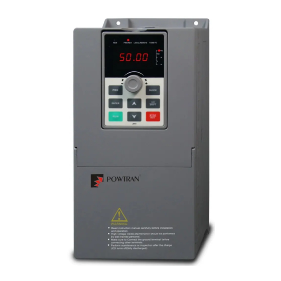
Page 4: Keyboard Description
4.Keyboard Description Diagram 4-1:Operation panel display 4.1 Keyboard Indicators Indicator flag Name Running indicator light *ON: the inverter is working *OFF: the inverter is stops Command indicator light ,That is the indicator for keyboard operation, terminal operation and remote LOCAL/ operation(communication control) REMOTE *ON: terminal control working status... - Page 5 Built-in PID Easy to realize closed-loop control system for the process control. Automatic voltage Automatically maintain a constant output voltage when the voltage of regulation(AVR) electricity grid changes Maximum light power tracking, light intensity automatic sleep, light Special function of intensity automatic wake up, high water level automatic shutdown, low solar water pump water level automatic operation, under-load protection etc...
-
Page 6: Wiring Diagram
6.Wiring diagram Main circuit wiring attentions (1)Wiring specifications, please implement wiring in accordance with electrical regulations; (2)Do not connect alternating current to the output end of the inverter (U, V, W), otherwise the inverter will be damaged; (3)Power supply wiring, please try to use the isolation wire and the wire tube, and the isolation wire or the two ends of the wire tube grounding;... - Page 7 After removing the starting capacitor, the internal wiring of the single-phase motor winding is shown in Figure 2: Before removal After removal Main Main Remove winding winding Secondary Secondary winding winding Figure 2 After removing the starting capacitor and running capacitor, the internal wiring of the single-phase motor winding is shown in Figure 3: Before After...
- Page 8 8.Brief table of parameters In PI500A-S series inverters, some parameters are "reserved by the manufacturer", and their serial Numbers are not listed in the function parameter table, which results in the disconnection of some parameter serial Numbers in the table. For the parameters not introduced in the manual, please do not try to modify them to avoid causing errors.
- Page 9 Upper limit frequency F0.22 0.00Hz~F0.19 (Maximum frequency) 0.00Hz ☆ offset ☆ F0.23 Lower limit frequency 0.00Hz~F0.21 (Upper limit frequency) 0.00Hz ☆ F0.24 Running direction 0:Same direction; 1: Opposite direction AI simulation quantity 0: 0.01Hz; 1: 0.05Hz; ☆ F0.26 accuracy 2: 0.1Hz; 3: 0.5Hz Down-conversion curve can make the inverter output frequency quickly decline, to avoid power shortage lead to undervoltage.
- Page 10 F2 group Output terminers parameters group Factory Code Parameter name Setting range Change setting F2.02 Relay 1 output function selection (TA1.TB1.TC1) ☆ 0~39 SPA output function selection (Collector open circuit F2.04 ☆ output terminals) Relay, SPA output terminals functions description as below: Setting Function Description...
- Page 11 F3 group Start-stop control parameter group Factory Code Parameter name Setting range Change setting 0:Direct startup; ☆ F3.00 Start-up mode 2:Pre-excitation start (AC asynchronous motor) F3.03 Start frequency 0.00Hz~10.00Hz 0.00Hz ☆ 0.0s~100.0s ★ F3.04 Hold time for start frequency 0.0s 0%~100% ★...
- Page 12 E0.03 (wake-up delay time), E0.09 (sleep frequency) and E0.11 (sleep delay time) functions only work when the sleep function setting (F6.13=1) is effective. Power correction coefficient 0.00~10.00 ☆ F6.17 1.00 0: Only RUN and STOP keys are valid. 2: Only RUN, STOP, UP, DOWN keys are valid ☆...
- Page 13 F7.39 Random arrivals current 2 width 0.0%~300.0% (Rated motor current) 0.0% ☆ F7.40 Module temperature arrival 0℃~100℃ 75℃ ☆ 0: Fan running only when running ☆ F7.41 Cooling fan control 1: Fan always running ★ F7.42 Timing function selection 0: Invalid 1: Valid 0: F7.44 setting 1: AI1...
- Page 14 selection 1: Compensation mode 1 2: Compensation mode 2 Current detection compensation 0~100 ☆ Fb.04 0: No optimization Vector optimization without PG ★ Fb.05 1: Optimization mode 1 mode selection 2: Optimization mode 2 Upper limiting frequency for ☆ Fb.06 0.00~15.00Hz 12.00Hz DPWM switching...
- Page 15 E1.09 9-stage speed setting 9X -100.0%~100.0% 0.0% ☆ E1.10 10-stage speed setting 10X -100.0%~100.0% 0.0% ☆ E1.11 11-stage speed setting 11X -100.0%~100.0% 0.0% ☆ E1.12 12-stage speed setting 12X -100.0%~100.0% 0.0% ☆ ☆ E1.13 13-stage speed setting 13X -100.0%~100.0% 0.0% ☆...
- Page 16 E2.05 PID inversion cutoff frequency 0.00~F0.19(Maximum frequency) 0.00Hz ☆ E2.06 PID deviation limit 0.0%~100.0% 2.0% ☆ E2.07 PID differential limiting 0.00%~100.00% 0.10% ☆ E2.08 PID reference change time 0.00s~650.00s 0.00s ☆ ☆ E2.09 PID feedback filter time 0.00s~60.00s 0.00s ☆ E2.10 PID output filter time 0.00s~60.00s 0.00s...
-
Page 17: Fault Alarm And Countermeasures
L group display selection(The same above) Units digit:Reserved Personality parameter y0.03 Tens digit :User’s change parameter display selection ☆ group display selection 0:Nodisplay 1:Display Function code 0:Modifiable; ☆ y0.04 modification properties 1:Not modifiable y1 group Fault query parameter group Factory Code Parameter name Setting range... - Page 18 No. Fault ID Failure type Possible causes Solutions is not suitable or V/F curve 3.The voltage is low 3.Set the voltage to the 4.The short-circuit or earthing of normal range inverter output happens 4.Eliminate peripheral faults 5.The control mode is vector and 5.Perform identification for without identification of parameters the motor parameters...
- Page 19 No. Fault ID Failure type Possible causes Solutions 1.Correctly set motor 1.The motor parameters was not set parameter according to the Motor parameter according to the nameplate Err.19 nameplate auto tuning fault 2.The identification process of 2.Check the lead wire from parameter is timeout the inverter to the motor EEPROM read...
- Page 20 Appendix: PI500A-S Installation dimension drawing of keyboard: Keyboard dimension drawing (dimension unit:mm) PI500&PI500A-S Dimension drawing of keyboard compartment: Dimension drawing of keyboard compartment (dimension unit: mm) Dimension drawing of PI500&PI500A-S keyboard installation opening : Opening size of external mounting panel Opening panel 126.5*82 T=1.0...
Need help?
Do you have a question about the PI500A-S Series and is the answer not in the manual?
Questions and answers