Table of Contents
Advertisement
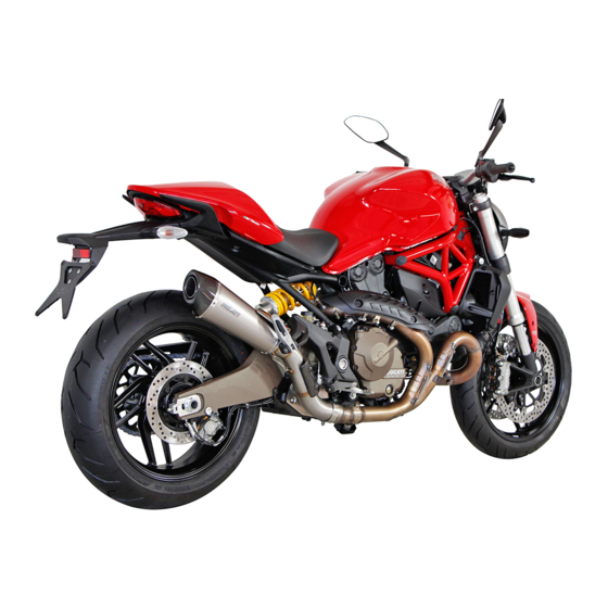
DUCATI MONSTER 821 Workshop
Manual 2015
M.01 - General
How to use this manual
Layout of the manual
Hazardous Products - Warnings
General maintenance instructions
M.02 - Information about the model
Model Identification data
M.03 - Technical data
Technical specifications
Injection system
Cooling system
Gearbox
Crankshaft
Charging system/generator
Rear suspension
Rear wheel
Front suspension
Front wheel
Cylinder/Piston
Timing system/valves
Transmission
Colours
General
Dimensions
Dimensions
Fuel, lubricants and other fluids
Torque settings
Service tools
Special diagnosis equipment
Special tools for the frame
Specific tools for the engine
M.04 - Maintenance operations
Vehicle pre-delivery
Scheduled maintenance chart
Operations to be carried out by the customer
Operations to be carried out by the dealer
Changing the timing belts
Adjusting the position of the gear change and rear brake pedals
1
Ducati Manuals Resource
Advertisement
Table of Contents

Related Manuals for Ducati MONSTER 821


Summary of Contents for Ducati MONSTER 821
- Page 1 DUCATI MONSTER 821 Workshop Manual 2015 M.01 - General How to use this manual Layout of the manual Symbols - Abbreviations - References Product specifications Hazardous Products - Warnings General maintenance instructions General safety rules M.02 - Information about the model...
- Page 2 Table I Table H Table G Table F Table E Table D Table C Table B Table A Routing of wiring on frame Key to fuse box Wiring diagram colour codes Key to wiring diagram Battery charging system Ducati Manuals Resource...
- Page 3 Trip meter 1 (TRIP A) Odometer (TOT) Menu 1 functions Engine coolant temperature Riding Mode Engine rpm indication (RPM) Motorcycle speed Main functions Parameter setting/displaying Function push-buttons Technological Dictionary Acronyms and abbreviations used in the Manual Display settings and functions Ducati Manuals Resource...
- Page 4 System components Accelerator position system (APS) CAN line Ducati traction control (DTC) Electronic throttle valve (ETV) Black Box System (BBS) Map Sensor Timing/rpm sensor Throttle Position Potentiometer Lambda sensor Electronic Control Unit (ECU) Handlebar controls: controls Right-hand switch Left-hand switch...
- Page 5 Rimontaggio fanale posteriore Smontaggio fanale posteriore Refitting the number plate holder Removing the number plate holder Electrical component tray Refitting the electrical component tray Removing the electrical component tray M.08 - Fuel system / Exhaust system Fuel tank Ducati Manuals Resource...
- Page 6 Removing the tensioner pins Removing the cylinder head pulley/idler pulley Removing the tensioner pulley/timing belt Removing the timing belt covers Cylinder head assembly: camshafts Refitting the intake manifold and water union Removing the intake manifold and water union Ducati Manuals Resource...
- Page 7 Crankcase assembly: crankcase halves Reassembling the crankcase halves Reassembling the crankcase halves Main bearing shells Overhauling the crankcase halves Separating the crankcase halves Crankcase assembly: connecting rods Refitting the connecting rod assembly Reassembling the connecting rod assembly Ducati Manuals Resource...
- Page 8 Overhauling the connecting rods Disassembling the connecting rod assembly Removing the connecting rod assembly Ducati Manuals Resource...
- Page 9 Multipurpose, medium fibre, lithium grease. SHELL Alvania GREASE Molybdenum disulphide grease, high mechanical stress and high SHELL Retinax temperature resistant. HDX2 GREASE Bearing/joint grease for parts subject to prolonged mechanical stress. SHELL Retinax Temperature range: -10 to 110 °C. Ducati Manuals Resource...
- Page 10 LOCK 7 Instant adhesive for rubber and plastics with elastomer charged ethylic Loctite 480 base. LOCK 8 High-strength retaining compound for threaded parts, bearings, bushes, Loctite 601 splines and keys. Operating temperature range: 55 to 150 °C. Ducati Manuals Resource...
- Page 11 LOCK Medium-strength threadlocker. Loctite 401 LOCK Instant adhesive gel offering tensile/shear strength. Loctite 454 gel DUCATI sealing compound. Three bond 1215 - Sealing compound Exhaust pipe sealing paste. Self-sealing paste hardens when heated and Holts Firegum resists temperatures exceeding 1000 °C.
- Page 12 Within every Riding Mode, the rider can customise any settings. Ducati Traction Control (DTC) The Ducati Traction Control system (DTC) supervises the rear wheel slipping control and settings vary through eight different levels that are programmed to offer a different tolerance level to rear wheel slipping.
- Page 13 Keep away from children. Coolant Engine coolant contains ethylene glycol, which may ignite under particular conditions, producing invisible flames. Although the flames from burning ethylene glycol are not visible, they are still capable of causing severe burns. Warning Ducati Manuals Resource...
- Page 14 The cooling fan operates automatically: keep hands well clear and make sure your clothing does not snag on the fan. Battery Warning The battery gives off explosive gases; never cause sparks or allow naked flames and cigarettes near the battery. When charging the battery, ensure that the working area is properly ventilated. Ducati Manuals Resource...
- Page 15 Coolant (ethylene glycol) is irritant and poisonous when ingested. Keep away from children. Never remove the radiator cap when the engine is hot. The coolant is under pressure and will cause severe burns. Ducati Manuals Resource...
- Page 16 The cooling fan operates automatically: keep hands well clear and make sure your clothing does not snag on the fan. Battery Warning The battery gives off explosive gases; never cause sparks or allow naked flames and cigarettes near the battery. When charging the battery, ensure that the working area is properly ventilated. Ducati Manuals Resource...
- Page 17 Model identification Identification data Each Ducati motorcycle is identified by two numbers, one for the frame and one for the engine. Note Please quote these numbers, which identify the motorcycle model, when ordering spare parts. DATA STAMPED ON THE FRAME...
- Page 18 Progressive serial no. Data stamped on the frame, Europe (Monster 821) and Australia version Data stamped on the frame, Europe (Monster 821 – 35 kW) version Data stamped on the frame, France (Monster 821 — 25 kW) version Manufacturer: Ducati Motor Holding...
- Page 19 Data stamped on the frame, USA/Canada, California version Manufacturer: Ducati Motor Holding Type Variant Version (X= Check Digit) Model Year (F= 2015) (G=...) Manufacturing facility Progressive serial no. DATA STAMPED ON ENGINE Data stamped on the Europe/France/Japan version engine Manufacturer: Ducati Motor Holding Engine type Progressive production no.
- Page 20 Data stamped on engine, Australia version Manufacturer: Ducati Motor Holding Engine type Progressive production no. Data stamped on the USA/Canada version engine Engine type Model Year (F= Model Tear 2015) (G=...) Progressive serial no. Ducati Manuals Resource...
- Page 21 Ducati Manuals Resource...
- Page 22 Injection system Make Type Control unit CONTINENTAL Ducati Manuals Resource...
- Page 23 Cooling system Reference Technical specifications Type Liquid-cooling with closed-circuit radiator, twin fan with thermostat Coolant 2.5±0.5 litres capacity Thermostat Starts opening at 65 °C ±2 °C Electric fan enabling 103 °C Electric fan disabling 100 °C Ducati Manuals Resource...
- Page 24 Gearbox Reference Standard value Service limit Gearbox shafts End float 0.05÷0.20 mm Selector drum End float 0.10÷0.40 mm Gear selector fork Fork slider thickness 3.90÷4.00 mm Fork–to-gear clearance 0.070÷0.285 mm 0.4 mm Ducati Manuals Resource...
- Page 25 Crankshaft Reference Standard value Service limit Crankshaft Oval 0.005 mm Taper 0.005 mm Main journal alignment 0.01 mm on diameter Ducati Manuals Resource...
- Page 26 LH fuse box key Optional key 7.5 A Alarm Stop Diagnostics Spare 7.5 A Spare 25 A Spare 30 A Key of fuses on solenoid starter ABOVE, Regulator Protection 30 A ABOVE, Regulator Protection 30 A SIDE, ABS 30 A Ducati Manuals Resource...
- Page 27 SIDE, ABS 25 A Ducati Manuals Resource...
- Page 28 95-98 RON Fuel specifications for the US market. Unleaded fuel with a minimum octane rating of 90 (RON+MON)/2 Throttle body MIKUNI with full Ride-by-wire system Diameter: 53 mm Injectors per cylinder no. 1 (39–N003) Firing points per injector Ducati Manuals Resource...
- Page 29 Technical specifications Ignition Type Electric with inductive discharge, mono Spark Starting Type Electric starter motor, 12 V - 0.7 kW Spark plugs Make and type NGK MAR9-J Electrode gap 0.8±0.1 mm Coils BERU Monospark (A0 040 100 503) Ducati Manuals Resource...
- Page 30 Voltage 12 V Charge 10 Ah Type dry, sealed, maintenance-free Generator Capacity DENSO ferrite 490W – 14 V – 34.8 A Rated power 487 Watt at 6000 rpm. Minimum 22 A with 14 Volt at 1500 rpm. Ducati Manuals Resource...
- Page 31 Drilled steel disc Thickness 4.2 mm 3.8 mm (min.) Diameter 245 mm Brake calliper Make Brembo Type P34e Calliper cylinder diameter 34 mm Pad friction material Toshiba TT2172 HH Master cylinder Type PS11 Master cylinder diameter 11 mm Ducati Manuals Resource...
- Page 32 0.5 turns (from fully closed position). preload: 15 mm (from fully uncompressed). "Comfort" adjustments rebound: 2.5 turns (from fully closed position). preload: 15 mm (from fully uncompressed). "Rider+Passenger" adjustments rebound: 1.5 turns (from fully closed position). preload: 19 mm (from fully uncompressed). Ducati Manuals Resource...
- Page 33 2.8 bar (with passenger) Swinging arm shaft runout On 100 mm 0.2 mm Wheel rim runout Radial 0.8 mm 2 mm Axial 0.5 mm 2 mm Drive chain Make REGINA Type 520 ZRDK Size 5/8” x 1/4” No. of links Ducati Manuals Resource...
- Page 34 Front suspension Reference Technical specifications Type KAYABA Hydraulic upside-down fork Leg diameter Ø 43 mm Travel on leg axis 130 mm Oil quantity, per leg 521 cc (right leg) 394 cc (left leg) Ducati Manuals Resource...
- Page 35 In the most worn part 2 mm Tyre pressure Cold 2.5 bar (rider only) 2.6 bar (with passenger) Wheel shaft runout On 100 mm 0.2 mm Wheel rim runout Radial 0.8 mm 2 mm Axial 0.5 mm 2 mm Ducati Manuals Resource...
- Page 36 Blue + Blue Blue + Yellow Big-end bearing-to- Crankpin A: Ø40.025 (+0.016; +0) mm crankpin clearance selection B: Ø40.025 (+0; -0.016) mm Gudgeon pin–to-piston 0.015 ÷ 0.024 mm clearance Nominal Ø 18 mm diameter Piston Ø 18(+0.020;+0.015) mm Ducati Manuals Resource...
- Page 37 Gudgeon pin Ø 18 mm (+0;-0.004) mm Gudgeon pin-to- 0.035 ÷ 0.049 mm connecting rod clearance Engine cylinder 11÷12 bar 10 bar (MIN.), difference compression measured between the two cylinders: 2 with DDS2 bar (MAX.) Ducati Manuals Resource...
- Page 38 Valve clearance Opening rocker arm - intake 0.13÷0.18 mm 0.10÷0.25 mm Opening rocker arm - exhaust 0.13÷0.18 mm 0.10÷0.25 mm Closing rocker arm - intake 0.05÷0.10 mm 0.05÷0.15 mm Closing rocker arm - exhaust 0.05÷0.10 mm 0.05÷0.15 mm Ducati Manuals Resource...
- Page 39 With constant mesh spur gears, operated by a lever on the left side of the motorcycle Transmission Gear ratios 37/15 2.467:1 30/17 1.765:1 28/20 1.400:1 26/22 1.182:1 24/23 1.043:1 23/24 0.958:1 Drive chain Make Regina Type 520 ZRDK Size 5/8" x 1/4" No. of links Ducati Manuals Resource...
- Page 40 Red frame (Ducati Red) 81784 (INVER SPA) Rear subframe (Matt Black Powder Enamel) CN201V (AKZO NOBEL) Rims (Red) Monster 821 DARK: seat cover not supplied. DARK STEALTH Primer (Black primer 2 K) 873.A002 (PALINAL) Primer (Black Stealth — Black 94) 929.R223 (PALINAL)
- Page 41 Rear wheel rim size MT5.50x17" Rear tyre size 180/60 - ZR 17 Type of tyres Radial, tubeless Front brake With drilled steel dual-disc ABS as a standard Rear brake With fixed drilled steel disc. ABS as a standard. Ducati Manuals Resource...
- Page 42 Forced by pump Oil pump type Lobe type, with bypass valve Cooling system Liquid cooling with thermostat Air filter One cylindrical filtering element Crankshaft type One-piece Clutch Wet, multiple plates with absorption and anti-hop mechanism Clutch control Cable type Ducati Manuals Resource...
- Page 43 Dimensions Ducati Manuals Resource...
- Page 44 Using fuel with ethanol content over 10% will make the warranty null and void. Engine oil A good quality engine oil has special properties. Use only a highly detergent engine oil with certified SE, SF or SG or higher service ratings as marked on the container. Ducati Manuals Resource...
- Page 45 Viscosity SAE 15W-50 The other viscosity grades specified in the table can be used where the average ambient temperatures are within the limits shown. Ducati Manuals Resource...
- Page 46 Head union for canister (USA version only) M6x1 (California versions) Horizontal head air breather union M6x1 LOCK 2 Vertical head air breather blanking screw M6x1 LOCK 2 Intake manifold retaining screw M6x1 MAP sensor special screw M6x1 Ducati Manuals Resource...
- Page 47 LOCK 2 (or TB 1324) Blow-by valve upper shell screw 1.4 LOCK 5 Electric starter Starter motor inner retaining TCEI screw M6x1 Pre-applied product Starter motor inner retaining TCEIF screw M6x1 Pre-applied product Starter motor outer retaining screw M6x1 Pre-applied product Ducati Manuals Resource...
- Page 48 FIXED tensioner bearing retaining screw M14x2 GREASE A Nut securing MOBILE tensioner M8x1.25 25 GREASE A Plastic cover retaining screw M6x1 Pre-applied product Cover filter self-tapping screw ST3.5 1.75 1.5 2 Covers Water intake union M30x1.5 25 LOCK 5 Ducati Manuals Resource...
- Page 49 Spark plug M10x1 Screw securing rotor to flywheel 25-35 M6x1 Pre-applied product Oil pump By-pass pump plug M15x1 LOCK 5 Oil lobe pump assembling screw 16-50 M6x1 Cylinders Water delivery union M22x1.5 25 LOCK 5 Cooling circuit Ducati Manuals Resource...
- Page 50 Water circuit ties Ducati Manuals Resource...
-
Page 51: Frame Tightening Torque Values
M5x0.8 Pre-applied threadlocker retainer Rear turn indicators to rear indicator spacer M5x0.8 Pre-applied threadlocker retainer RH/LH turn indicator support cover to rear M5x0.8 RH/LH turn indicator support retainer Rear turn indicator support to special screw M6x1 retainer Ducati Manuals Resource... - Page 52 Screw securing solenoid starter cover to M5x0.8 electric component support Screw securing fuse support rubber bracket to M3.5 electric component support Screw securing electric component pin to M10x1.25 20 GREASE B electric component LH bracket Ducati Manuals Resource...
- Page 53 Screw securing front brake master cylinder to M6x1 Sequence 1-(UP)-2-1 handlebar Front brake calliper retaining screw (RH+LH) M10x1.25 45* GREASE B Front brake calliper pre-tightening for settling M10x1.25 2 GREASE B (RH+LH) Union on brake master cylinder tightening M10x1 Ducati Manuals Resource...
- Page 54 M6x1 10-15 Screw securing clutch cable plate to engine M6x1 Rear suspension Screw securing shock absorber to vertical M10x1.25 42* GREASE B head Screw securing shock absorber to rear M10x1.25 42* GREASE B swinging arm Front mudguard Ducati Manuals Resource...
- Page 55 Screw retaining silencer heel guard to footpeg M5x0.8 Pre-applied threadlocker holder plate Screw securing brake fluid reservoir support to M6x1 LOCK 2 footpeg holder plate Footpeg holder plate and rear subframe to M12x1.25 60* GREASE B engine retaining nut Ducati Manuals Resource...
- Page 56 Cush drive damper pin to driving flange M14x1.5 44* LOCK 5 retainer Rear sprocket to driving flange retainer M10x1 LOCK 2 LOCK 8 - Manually tighten nut until Rear wheel shaft pre-assembly M30x1.5 exceeding pin threading end by 1.25 Ducati Manuals Resource...
- Page 57 Exhaust valve cover retaining screw M6x1 Vertical primary heat guard (plastic) retaining M6x1 screw Vertical and vertical primary manifold retaining clamp Vertical manifold heat guard retaining clamps Vertical primary pipe heat guard retaining clamps Silencer endcap retainer M6x1 Ducati Manuals Resource...
- Page 58 Screw securing air temperature sensor to airbox upper box (ATS05 Marelli) Screw securing clamp base (RICHO) to airbox upper box Screw securing throttle body to airbox lower M6x1 Screw securing fuel pipes to throttle body M5x0.8 Ducati Manuals Resource...
- Page 59 Rear - front subframe special screw retaining M8x1.25 20 screws Rear - rear subframe special screw retaining M8x1.25 20 screws Side cover to wiring support retaining screws M5x0.8 *dynamic safety-critical point; tightening torque tolerance must be Nm ±5%. Ducati Manuals Resource...
- Page 60 Diagnosis special tools PART NO. DESCRIPTION IMAGE 28620441A “PC HASP DDS2.0” wrench 979000252 DDS 2 (Ducati Diagnosis System 2.0) 979000253 Belt tensioning 979000254 Diagnosis and power supply cable 979000255 Diagnosis and power supply cable (CAN) 979000256 Power supply cable from DDS battery...
- Page 61 Traction bar for Kayaba fork overhaul 88713.0957 Preload tube retaining tool for Kayaba fork 88713.1058 Wrench to fit steering tube plug 88713.1062 Steering tube bearing installation tool 88713.1074 Swingarm shaft removal tool 88713.1096 Driving tool for Kayaba fork oil seal Ducati Manuals Resource...
- Page 62 88713.2409 Ball bearing installation tool 88713.3220 Engine repair work bench 88713.4513 Frame/engine support Ducati Manuals Resource...
- Page 63 88713.0869 Water pump front seal installation tool 88713.0870 Water pump front seal counter-washer installation tool 88713.0944 Oil cartridge wrench 88713.1749 Puller for driving pulley and cover 88713.1805 Driving pulley tightening tool 88713.1806 Camshaft pulley (Z=20) tightening tool Ducati Manuals Resource...
- Page 64 88713.2011 Tool to block crankshaft at Top Dead Centre (TDC) 88713.2087 Gauge to check Top Dead Centre (TDC) 88713.2092 Primary drive gear puller 88713.2442 Tool to install seal ring on valve guide 88713.2556 Clutch housing reaction tool Ducati Manuals Resource...
- Page 65 88713.2676 Cylinder head nut tightening tool 88713.2834 Snap ring installation tool 88713.2861 Camshaft seal ring installation tool 88713.2863 Bearing surface for head installation 88713.2870 Con-rod guiding tool 88713.2877 Spark plug wrench 88713.2878 Spacer and fork feeler gauge 0.2/0.3 mm Ducati Manuals Resource...
- Page 66 88713.2906 Oil cartridge wrench 88713.3219 Reaction tool for pulley tightening 88713.3334 Selector fork positioning plate 88713.3367 Flywheel wrench 88713.3497 Wrench to tension the belt mobile tensioner 88713.3992 Piston pin circlip fitting tool 88713.4145 Main bearing shell assembling tool Ducati Manuals Resource...
- Page 67 88713.4198 vertical cylinder exhaust manifold upper nut disassembly tool 88713.4284 Clutch pack assembly reaction tool 88713.4285 Clutch pack locking screws 88713.4286 Clutch pack assembly/disassembly support 88713.4411 Insert (together with part no. 88713.2011) 88713.4803 Special socket wrench 18 to tighten mesh filter Ducati Manuals Resource...
- Page 68 88765.1000 88765.1005 Fork feeler gauges 88765.1006 88765.1298 Valve lower shim check spacer 88765.1523 Timing check tool 88765.1623 Timing pulley positioning tool Ducati Manuals Resource...
- Page 69 Check the presence of any technical updates and recall campaigns on DCS. • Install any Ducati Performance accessories required by Customer's order and check their operation. • Final test and road test of the motorcycle (test correct operation of safety devices and electric fan).
- Page 70 Check tyre pressure and wear • Check the drive chain tension and lubrication • Check brake pads • * Service operation to be carried out in accordance with the specified distance or time intervals (km, miles or months), whichever occurs first. Ducati Manuals Resource...
- Page 71 • • • • 12 Check rubbing points, clearance, freedom of movement and positioning of hoses • • • • • 12 and electric wiring in view Lubricate the levers at the handlebar and pedal controls • • • • 12 Ducati Manuals Resource...
- Page 72 • • • • 12 DTC), electric fans and idling Softly clean the motorcycle • • • • • 12 Fill out that the service was performed in on-board documentation (Service • • • • • 12 Booklet) Ducati Manuals Resource...
- Page 73 Using the special tool part no. 88713.1058 lock the ring nut (3) to a torque of 30 Nm ±5%. Push the steering head against the ring nut (3) and tighten the screws (1) to a torque of 18Nm ±5% and screws (2) to a torque of 24Nm ±5%. Ducati Manuals Resource...
- Page 74 Ducati Manuals Resource...
- Page 75 Change timing belts To replace the timing belts follow the procedure described under paragraphs "Removing the mobile belt" and "Refitting the timing tensioner/timing belts". Ducati Manuals Resource...
- Page 76 To turn the preload adjuster ring nut use a pin wrench. Pay attention to avoid hand injuries by hitting motorcycle parts in case the wrench tooth suddenly slips on the ring nut groove while moving it. Warning Ducati Manuals Resource...
- Page 77 0.5 turns (from fully closed position). preload: 15 mm (from fully uncompressed). "Comfort" adjustments rebound: 2.5 turns (from fully closed position). preload: 15 mm (from fully uncompressed). "Rider+Passenger" adjustments rebound: 1.5 turns (from fully closed position). preload: 19 mm (from fully uncompressed). Ducati Manuals Resource...
- Page 78 Operate the pedal by hand to check that there is 1.5 to 2 mm of free play before the brake bites. If not, adjust the length of the master cylinder pushrod. Tighten the check nut (4) to a torque of 5Nm ±10%, and check play again. Ducati Manuals Resource...
- Page 79 Also check stop plate of stop sensor. Ducati Manuals Resource...
- Page 80 To adjust the distance, loosen nut (10), set the right distance of dowel (11) and tighten nut (10) to a torque of 8Nm±10%. Check the distance again and, if non conforming, repeat the procedure. Warning The nut tightening procedure must be carried out while dowel is tight. Ducati Manuals Resource...
- Page 81 Ducati Manuals Resource...
- Page 82 Keep in mind that the position no. 1 corresponds to the maximum distance between the lever and the handgrip, whereas position no. 4 corresponds to the minimum distance. Warning Set front brake lever when motorcycle is stopped. Ducati Manuals Resource...
- Page 83 Important Change both pads even if just one of them is worn. Change the brake pads as follows. Remove the snap ring (8) from the pad retaining pin (9). Slide pad retaining pin (9) outwards. Ducati Manuals Resource...
- Page 84 Remove pad retaining clip (10) from between the two calliper halves. Remove the rear brake calliper by loosening the screws (11). Ducati Manuals Resource...
- Page 85 Force the calliper pistons back into their seats by forcing the old brake pads apart. Remove the worn pads (12). Fit the new pads. Refit rear brake calliper, then start and tighten the screws (11) to a torque of 25 Nm ± 5%. Ducati Manuals Resource...
- Page 86 Insert pad retaining clip (10) and centring pin (9), locking it in place with ring (8). Ducati Manuals Resource...
- Page 87 Ducati Manuals Resource...
- Page 88 Operate the brake pedal repeatedly so that the pads firmly bed in against the disc thanks to the brake fluid pressure. Check that the fluid level inside reservoir is between the "MIN" and "MAX" marks. If this is not the case, unscrew the reservoir cover (6) and top up. Ducati Manuals Resource...
- Page 89 Being the brake callipers a safety component of the motorcycle, follow the instruction indicated in section "Removing the front brake system" and "Removing the complete rear brake control", and remember to tighten the rear brake calliper screws (11) to a torque of 25Nm ± 5% upon refitting. Ducati Manuals Resource...
- Page 90 Work in the same way on both front brake callipers. Loosen the two screws (1) and remove calliper from disc. Remove the safety split pin (2). Turn shaft (3) clockwise and slide it out. Remove the spring (4). Ducati Manuals Resource...
- Page 91 Force the calliper pistons back into their seats by forcing the old brake pads apart. Remove the worn pads (5). Note Change pads that have a shiny or "vitrified" appearance. Fit the new pads and their spring (4) making sure to position it as shown. Ducati Manuals Resource...
- Page 92 Fit the pad retaining pin (3) and fasten it with safety split pin (2). Pre-tighten screws (1) to a torque of 2Nm ± 10%, then tighten them to a torque of 25Nm ± 5%. Ducati Manuals Resource...
- Page 93 If necessary, top up by loosening the two screws (7) and removing cover (8), until reaching the "MAX" level. Being the brake callipers a safety component of the motorcycle, follow instructions indicated in "Removing the front brake system". Close cover (8) and tighten the two screws (7). Ducati Manuals Resource...
- Page 94 An incorrectly tensioned chain will lead to early wear of the transmission components. Check the correspondence of the positioning marks, working on both sides of the swinging arm to ensure a perfect wheel alignment. Warning Correct tightening of swinging arm screws (2) is critical to rider and passenger safety. Ducati Manuals Resource...
- Page 95 Grease the nut thread (1) with the specified product and tighten nut to a torque of 145 Nm. Grease the adjuster screw thread (2) with the specified product and tighten screws to a torque of 10 Nm. Ducati Manuals Resource...
-
Page 96: Clutch Control Cable Adjustment
(4) and must not touch edge (5) of stop plate (6). Operate the lever through its free play and check that distance "B" is between 2 mm and 3 mm. Use a gauge as reference, and check that distance "A" is higher or equal to 5 mm. Ducati Manuals Resource... - Page 97 Adjuster (3), located on the lever, allows , through ring nut (2), a maximum adjustment of 11 mm, whereas the standard setting (starting one) is of 5 mm. Warning In case of a slipping clutch due to clutch wear, adjuster on the lever must NEVER be loosened, but screwed, as described above. Ducati Manuals Resource...
- Page 98 To decrease distance (A), decrease the free play by loosening adjuster (10) and then tightening • adjuster (3) ring nut (2). Tighten nut (9) to the specified torque while holding adjuster (10) and bring protective caps (7) and (8) back in place. Repeat all the tests. Ducati Manuals Resource...
- Page 99 Attach a transparent plastic tubing to the bleed valve (3) and insert the other end of the tubing in a container placed on the floor. Siphon the fluid from the reservoir (2). Fill the reservoir (2) with new oil up to the "MAX" mark. Ducati Manuals Resource...
- Page 100 The pedal is at the end of travel when it is in the lower position. Now, screw bleed valve (3) to a torque of 4Nm ±10%, and release the pedal; press the pedal again. Repeat the above operation until the old fluid flows out completely. Ducati Manuals Resource...
- Page 101 During this operation, fluid level inside reservoir must remain above the MIN mark at all times. The end of the transparent plastic hose must remain immersed in the discharged fluid at all times. Operate brake pedal and keep it pressed during the whole filling operation. BLEEDING THE REAR BRAKE SYSTEM Ducati Manuals Resource...
- Page 102 Make sure that, with bleed valve duly closed, pressure is correctly developed through brake pedal. Tighten bleed valve (3) to a torque of 4Nm ± 10%, and fit protective cap. Level fluid and refit cover (1) on reservoir (2). Ducati Manuals Resource...
- Page 103 Ducati Manuals Resource...
- Page 104 Ducati Manuals Resource...
- Page 105 (5) a transparent tube by immersing the end in a container placed on the floor. Fill up the reservoir (2) with new oil until the sight glass (A) is covered. Ducati Manuals Resource...
- Page 106 Pull the lever to make a 20 - 30 mm stroke and keep the lever in this position using a non-elastic clamp. Loosen the bleed valve of the left-hand calliper (as seen by the rider) (5) and then take the lever through the whole stroke to allow fluid to flow out. The lever is resting against the handgrip. Ducati Manuals Resource...
- Page 107 With this procedure, the front brake system callipers are still filled with fluid; if callipers have to be drained as well, move back calliper pistons by keeping the bleeding tool (if available) working and connected to bleed valve. Fill the reservoir (2) with the specified fluid taken from an intact container. Important Ducati Manuals Resource...
- Page 108 If you do not have a bleeding tool available, connect a transparent plastic tubing to the bleed valve (5) as outlined in the draining procedure. Operate the lever to half stroke or until system is pressurised, open bleed valve (5) and operate lever to full stroke; tighten bleed valve to the specified torque and release lever. Ducati Manuals Resource...
- Page 109 Make sure that, with bleed valves duly closed, pressure is correctly developed through brake lever or pedal. Close bleed valves (5) to a torque of 4 Nm ± 10%, and fit protective caps. Level fluid and refit cover (1) by tightening screws (3) on reservoir (2). Ducati Manuals Resource...
- Page 110 Loosen screw (A) and keep spacer (B), sliding cover (C) out of frame tabs (D). Place a container under the engine and set the motorcycle on its side stand. Remove the expansion reservoir filler plug (1). Loosen radiator plug (2) and remove cover (3). Ducati Manuals Resource...
- Page 111 Loosen plug (6) from fluid drain hole located on the pump cover. Allow the coolant to drain off completely. Screw plug (6) in the fluid drain hole with a new seal. Tighten plug (6) to a torque of 20Nm ± 10%. Ducati Manuals Resource...
- Page 112 Insert hose (5) and secure it to radiator with clamp (4). Fill the circuit with new coolant through radiator filler plug inlet. Ducati Manuals Resource...
- Page 113 Tighten the plug (1) of the expansion reservoir. If previously removed, refit coolant tank cover (C), locking it inside frame tabs (D). Position spacer (B) behind cover, and tighten screw (A) to a torque of 1Nm ± 10%. Ducati Manuals Resource...
- Page 114 Ducati Manuals Resource...
- Page 115 Very hard water with a high mineral salt content can damage the engine. Increase the amount of antifreeze to up to 55% volume in the case of very cold climates. Important Solutions with less than 30% of antifreeze will not provide sufficient protection against corrosion. Ducati Manuals Resource...
- Page 116 A clogged air filter will reduce air intake and engine power, increase fuel consumption and cause a build up of deposits on the spark plugs. Do not use the motorcycle without a filter as impurities in the air could get into the engine and cause damage. Ducati Manuals Resource...
- Page 117 10 Nm (Min. 9 Nm - Max. 11 Nm) for plastic covers and 6 Nm (Min. 5.5 Nm - Max. 6.5 Nm) for carbon covers. Refit primary exhaust pipes (Refitting the exhaust system), complete with heat guards. Ducati Manuals Resource...
- Page 118 Refit the fuel tank (Refitting the fuel tank). Refit the seat (Refitting the seat). Ducati Manuals Resource...
- Page 119 If a spark plug is loose, it can overheat and damage the engine. Spark plug type Make: NGK Type: MAR9A-J Remove the seat (Removing the seat). Remove the fuel tank (Removing the fuel tank). Slide caps (9) out of vertical head. Ducati Manuals Resource...
- Page 120 To reach horizontal head spark plug, loosen threaded pin (10) securing water radiator, working on both sides, and slightly moving it towards forks. Slide cap (11) out of horizontal head. Ducati Manuals Resource...
- Page 121 Work in the same way on both heads. Secure water radiator to support by starting and tightening threaded pins (10) to a torque of 5 Nm ± 10%. Refit the fuel tank (Refitting the fuel tank). Refit the seat (Refitting the seat). Ducati Manuals Resource...
- Page 122 (Removing the secondary air system). Remove the cylinder head cover (Removing the camshafts). Note For clarity, the figures show the engine removed from the frame. Loosen the two screws (1) retaining cover (2) and remove them together with gasket (3). Ducati Manuals Resource...
- Page 123 (Removing the valves), and replace it with one of suitable height to obtain the prescribed clearance. Note Opening rocker arm shims measuring 1.80 to 3.45 are available as spare parts: the size is punched on the shim. Ducati Manuals Resource...
- Page 124 During this operation, press on the camshaft perpendicularly to the head surface to keep it in seat. The value must be within the prescribed ones (Timing system/valves). Reference Assembly value Check value every 24,000 km Valve clearance Closing rocker arm - intake 0.05÷0.10 mm 0.05÷0.25 mm Ducati Manuals Resource...
- Page 125 If not, remove the closing shim (5), as described in paragraph (Removing the valves), and replace it with one of suitable height to obtain the prescribed clearance. Note Closing rocker arm shims measuring 2.2 to 4.5 are available as spare parts: the size is punched on the shim. Ducati Manuals Resource...
- Page 126 Restore the original conditions by refitting the previously removed components. Ducati Manuals Resource...
- Page 127 Dispose of oil and/or filter cartridges in compliance with environmental protection regulations. Remove any metal deposits from the end of the magnetic drain plug (3) and refit the drain plug complete with seal (A) to the sump. Ducati Manuals Resource...
- Page 128 Fit a new cartridge (4) using tool no. 88713.0944 (A) tightening it to a torque of 11 Nm (Min. 10 Nm - Max 12 Nm): lubricate seal with engine oil. Note It is advisable to refill the filter cartridge with engine oil before fitting it: this enables the recommended oil level to be maintained without topping up. Ducati Manuals Resource...
- Page 129 Screw it into relevant seat and tighten it to 11 Nm (Min. 10 Nm - Max. 12 Nm). Every two oil changes, clean the oil intake mesh filter. Loosen outer plug (5) and collect seal (6). Ducati Manuals Resource...
- Page 130 Loosen filtering element (7) using suitable tool part no. 88713.4803 and slide it out. Loosen lower plug (8) and collect seal (9). Clean the filter with fuel and compressed air. Take care not to damage the mesh. Ducati Manuals Resource...
- Page 131 Tighten plug (5) to a torque of 42 Nm (Min. 38 Nm - Max. 46 Nm). Position seal (9) in hole and lubricate intake service plug thread (8) with grease to a torque of 25 Nm (Min. 22 Nm - Max. 28 Nm). Ducati Manuals Resource...
- Page 132 Remove the filler plug (2) and carry out refilling with the specified oil type up to reaching the notch that identifies the MAX level in the sight glass. Refit the filler plug (2). Run the engine at idle speed for a few minutes. Ducati Manuals Resource...
- Page 133 If not, stop the engine and trace the fault. After a few minutes, check that the oil level is the specified one; if necessary, restore the MAX. level. Refit the central exhaust system (Refitting the exhaust system) Refit any removed parts. Ducati Manuals Resource...
- Page 134 Oil level must be checked with the vehicle perfectly upright and the engine cold. Oil level must be between the MIN and MAX marks. Top up if the level is low. Remove the filler plug (2) and top up with the recommended oil. Refit the filler plug (2). Ducati Manuals Resource...
- Page 135 25 Nm ± 10%. Follow the same procedure on the LH rear-view mirror (4) and tighten screw (3) to a torque of 25 Nm ± 10%. Warning The screw features a left-hand thread: tighten it counter clockwise. Ducati Manuals Resource...
- Page 136 Loosen the screw (1) and remove it collecting the lower washer. Remove the RH rear-view mirror (2). Loosen the screw (3) and remove it collecting the lower washer. Remove the LH rear-view mirror (4). Warning The screw features a left-hand thread: loosen it clockwise. Ducati Manuals Resource...
- Page 137 Refitting the instrument panel assembly After having applied the specified product on vibration damper (6), position instrument panel (5) on support (7). Connect the instrument panel connector (4). Ducati Manuals Resource...
- Page 138 Secure instrument panel cover (1) using the two screws (2), with spacers (3), tightening them to a torque of 2Nm ± 10%. Close instrument panel cover (1) by coupling tabs (C) and (D) with tabs (E) and (F). Ducati Manuals Resource...
- Page 139 Ducati Manuals Resource...
- Page 140 Press on instrument panel cover (1) tabs (A) and (B), open them outwards sliding tabs (C) and (D) out of their seats. Loosen the two screws (2) and collect the two spacers (3). Slide out instrument panel cover (1). Disconnect the instrument panel connector (4). Ducati Manuals Resource...
- Page 141 Slide instrument panel (5) out pulling it up. Ducati Manuals Resource...
- Page 142 Refitting the seat bottom cover Refitting the seat bottom cover is the reverse of the procedure described in "Removing the seat bottom cover". Ducati Manuals Resource...
- Page 143 (Removing the seat release mechanism). Refit the splash guard (only for Australia version) and the number plate holder (Removing the number plate holder). Remove the rear grab handles (Removing the rear grab handles). Remove seat bottom cover. Ducati Manuals Resource...
- Page 144 Tighten the four special screws (1) to a torque of 20 Nm ± 10%. Refit the number plate holder and the splash guard (only for Australia version) (Refitting the number plate holder). Refit the seat (Refitting the seat). Ducati Manuals Resource...
- Page 145 Remove the seat (Removing the seat). Remove the number plate holder and the splash guard (only in the Australia version) (Removing the number plate holder). Undo special screws (1) to remove rear grab handles (2) and (3). Ducati Manuals Resource...
- Page 146 Fit lock (6) in the relevant hole on the RH side of the rear tail guard. Fit plate (5) by starting ring nut (4) and tighten it to a torque of 3 Nm ± 10%. Warning Move the ring nut until the collar is facing downwards. Ducati Manuals Resource...
- Page 147 Fit nipple (1) into its seat (3). Position latch (7) as shown in the figure and tighten the two screws (8) to a torque of 5 Nm ± 10%. Ducati Manuals Resource...
- Page 148 Refit the seat (Refitting the seat) Ducati Manuals Resource...
- Page 149 Removing the seat release mechanism Remove the seat (Removing the seat). Slide nipple (1) of the seat lock cable (2) out of its seat (3). Loosen the ring nut (4) and remove plate (5). Remove lock (6). Ducati Manuals Resource...
- Page 150 Remove latch (7) by loosening the two screws (8). Working on the right side, release cable (9) from cable ring (10) to remove it from the seat lock. Ducati Manuals Resource...
- Page 151 Ducati Manuals Resource...
- Page 152 Refitting the seat covers If previously removed, fit the two side panels (9) and tighten the two relevant screws (8) to a torque of 3 Nm ± 10%. Warning Properly insert the front tabs on the subframe tube. Ducati Manuals Resource...
- Page 153 If previously removed, refit seat cover (11) and secure it by engaging the lower tabs (13) (not for Dark version). Tighten the two lower screws (12) to a torque of 3Nm ± 10%. Ducati Manuals Resource...
- Page 154 Then check the position of elastic (C) and pin (4) according to the seat configuration (HIGH or LOW). Position seat (1) on the motorcycle. The front tabs (2) of the seat must be engaged on buffers (C) and (D) of pin (4). Ducati Manuals Resource...
- Page 155 Pin (7) in the rear part of seat (1) must be positioned so as to be aligned with seat (8) on the rear subframe. Lower the seat (1) and press on the seat rear side to properly engage it. Ducati Manuals Resource...
- Page 156 Ducati Manuals Resource...
- Page 157 The vehicle in the basic condition is in the "HIGH SEAT" configuration. "LOW SEAT" position To modify the riding position in "LOW SEAT" proceed as follows. Working on both sides, loosen the two screws (2) and remove side covers (3). Ducati Manuals Resource...
- Page 158 Move the seat pin (4) from seat (A) to seat (B). Slide out the two rear (5) and the two front (6) "HIGH SEAT" supports by pressing them on the longest sides. Ducati Manuals Resource...
- Page 159 Note The front and rear buffers differ from each other. To identify them refer to the indication printed on them (FRONT) or (REAR). Ducati Manuals Resource...
- Page 160 Removing the seat covers If necessary, remove the side panels (9) from the frame following the same procedure, i.e. loosen the relevant two retaining screws (8) and collect toothed washers (16). Ducati Manuals Resource...
- Page 161 If necessary, loosen the two lower screws (12), remove seat cover (11) and replace it (not for Dark version). Ducati Manuals Resource...
- Page 162 Note If the screws are new, apply specified threadlocker on screw threads. Tighten the screw (3) to a torque of 5 Nm ± 10%. If the rear wheel has been removed, refit it (Refitting the rear wheel). Ducati Manuals Resource...
- Page 163 Removing the rear mudguard If necessary, remove the rear wheel to remove the rear mudguard (1) (Removing the rear wheel). Loosen the two central screws (2). Loosen the LH side screw (3) and slide the rear mudguard out. Ducati Manuals Resource...
- Page 164 If screws (5) are not new, apply specified threadlocker. Fit washers (6) to the relevant screws (4). Start screws (5) securing front mudguard (4) to the forks. Tighten screws (5) to a torque of 8 Nm ± 10 %. Ducati Manuals Resource...
- Page 165 Ducati Manuals Resource...
- Page 166 Ducati Manuals Resource...
- Page 167 Removing the front mudguard Loosen screw (1) and collect washer (2), slide cable ring (3) out of front mudguard (4). Loosen screws (5) that retain the front mudguard (4) and collect the relevant spacers (6) on both sides. Ducati Manuals Resource...
- Page 168 Slide out front mudguard (4) from the front side having care not to damage the forks and the braking system. Ducati Manuals Resource...
- Page 169 Table V MAP sensor, fuse boxes, ABS control unit MAP sensor MAP sensor (75). Ducati Manuals Resource...
- Page 170 Fuse boxes The front fuse box wiring (78) has more wires than the rear fuse box wiring (77). The front fuse box wiring (78) is longer than the rear fuse box wiring (77). Ducati Manuals Resource...
- Page 171 ABS control unit wiring Ducati Manuals Resource...
- Page 172 For the complete index of the wirings, divided by tables, refer to chapter "Routing of wiring on frame". Ducati Manuals Resource...
- Page 173 Table U Airbox In order to identify the injector wiring branches, cables are marked with "V" (vertical) (74) and "O" (horizontal) (73) labels. Tie together the fuel-throttle body hose and the injector wiring (6), in the indicated position. Ducati Manuals Resource...
- Page 174 Tie together the horizontal injector wiring (73) and the vertical injector wiring (74), as indicated. The wiring of this vehicle features a female connector for connector (6) of injectors (4) and a male connector for the potentiometer. Ducati Manuals Resource...
- Page 175 Make sure that the potentiometer wiring (4) is not squeezed between the fuel pipe (AC) and the throttle body surface (AD). Check that wiring (6) and fuel-throttle body pipe come out of the airbox with the relevant seals in their seats, as indicated. Ducati Manuals Resource...
- Page 176 For the complete index of the wirings, divided by tables, refer to chapter "Routing of wiring on frame". Ducati Manuals Resource...
- Page 177 A correct positioning of the rear guard wiring (69) implies a better position of the LH (70) and RH (71) turn indicator wirings and of the number plate light wiring (72). The RH (71) and LH (70) turn indicator wiring branches are identified by specific labels with the writing "RH" and "LH”. Ducati Manuals Resource...
- Page 178 For the complete index of the wirings, divided by tables, refer to chapter "Routing of wiring on frame". Ducati Manuals Resource...
- Page 179 Table S Rear subframe Tie the wirings as indicated. Lower view Upper views Ducati Manuals Resource...
- Page 180 Pay attention to the rear guard wiring passage (69). For the complete index of the wirings, divided by tables, refer to chapter "Routing of wiring on frame". Ducati Manuals Resource...
- Page 181 Table R Rear subframe and BBS control unit wiring Tie the BBS wiring (63) and the rear subframe branch (64), as indicated. Ducati Manuals Resource...
- Page 182 Connect the connector to the BBS control unit (65). For the complete index of the wirings, divided by tables, refer to chapter "Routing of wiring on frame". Ducati Manuals Resource...
- Page 183 Table Q Wiring for rear speed and rear stop sensor Tie the rear stop light wiring (62) with the rear speed sensor cable (61) as indicated. Ducati Manuals Resource...
- Page 184 Tie rear stop light cable (62) and the relevant branch to the rear brake master cylinder hose (AB). Ducati Manuals Resource...
- Page 185 Fasten the rear speed sensor cable (62) and the rear brake master cylinder hose to the hose passage (AA). For the complete index of the wirings, divided by tables, refer to chapter "Routing of wiring on frame". Ducati Manuals Resource...
- Page 186 Ducati Manuals Resource...
- Page 187 Table P Electrical component box: solenoid starter, battery Ducati Manuals Resource...
- Page 188 For the complete index of the wirings, divided by tables, refer to chapter "Routing of wiring on frame". Ducati Manuals Resource...
- Page 189 Table O Electrical component compartment and box Tie together the voltage regulator wiring (53) and the generator cable (47), where indicated. Ducati Manuals Resource...
- Page 190 Electrical components box For the complete index of the wirings, divided by tables, refer to chapter "Routing of wiring on frame". Ducati Manuals Resource...
- Page 191 (X): the cable sheath of the horizontal cylinder lambda sensor (50) must be brought as close as possible to the lambda sensor. Attention FOR SAFETY REASONS, THE LAMBDA SENSOR CABLE MUST BE KEPT DISTANT FROM THE EXHAUST WITHOUT BEING TOO MUCH TENSIONED. Ducati Manuals Resource...
- Page 192 USA VERSION (Y): tie the still air hose with the lambda sensor cable (50) of the horizontal cylinder. For the complete index of the wirings, divided by tables, refer to chapter "Routing of wiring on frame". Ducati Manuals Resource...
- Page 193 Ducati Manuals Resource...
- Page 194 Table M Crankcase LH/lower cables Ducati Manuals Resource...
- Page 195 Six ties fasten the side stand sensor cable (49), the battery negative cable (40) and the starter motor solenoid starter cable (48) against the lower side body panel. Note Tie the side stand sensor cable in the marked point. Ducati Manuals Resource...
- Page 196 Two ties (Z1) fasten the main wiring (41) to the lower side body panel. Warning Aim tie closure as shown in the figure. Ducati Manuals Resource...
- Page 197 Make sure to respect the distance between the ties of side body panel indicated in the figure. Tie main branch (41), generator cable (47), battery negative cable (40) and starter motor/solenoid starter cable (48) to the electrical component box. Ducati Manuals Resource...
- Page 198 Route the indicated wirings in the relevant support opening, as indicated. For the complete index of the wirings, divided by tables, refer to chapter "Routing of wiring on frame". Ducati Manuals Resource...
- Page 199 Table L LH side wiring branch: coils, pick-up Ducati Manuals Resource...
- Page 200 Tie the pick-up wiring (44) to the expansion reservoir, by orienting the tie closing towards the reservoir. Close the tie without squeezing the expansion reservoir hose. USA VERSION Ducati Manuals Resource...
- Page 201 Warning The pick-up cable must pass over the canister pipes. For the complete index of the wirings, divided by tables, refer to chapter "Routing of wiring on frame". Ducati Manuals Resource...
- Page 202 Table K Vertical head LH side wiring branch: temperature and ground sensor For the complete index of the wirings, divided by tables, refer to chapter "Routing of wiring on frame". Ducati Manuals Resource...
- Page 203 Table J Tank ground and fuel pump wiring For the complete index of the wirings, divided by tables, refer to chapter "Routing of wiring on frame". Ducati Manuals Resource...
- Page 204 Vertical head LH side wiring branch T: Zero point of the vehicle electric system. Use two ties to fasten the rear branch (35) to the vertical head cover, positioning the tie closure as indicated in the figure. Ducati Manuals Resource...
- Page 205 For the complete index of the wirings, divided by tables, refer to chapter "Routing of wiring on frame". Ducati Manuals Resource...
- Page 206 Engage RH fan connector (30) to tab (Q) on the frame. Engage speed sensor connector (31) to tab (R) on the frame. Fasten the speed sensor cable (31) to the front brake hose through the ten indicated cable rings (O). Ducati Manuals Resource...
- Page 207 Then fasten the speed sensor cable (31) in the front brake bleed cap (P). Ducati Manuals Resource...
- Page 208 Fasten the speed sensor cable (31) on hose clamp (S) inside the left leg. Connect the secondary air sensor (32) to the actuator after positioning the wiring as indicated. Ducati Manuals Resource...
- Page 209 For the complete index of the wirings, divided by tables, refer to chapter "Routing of wiring on frame". Ducati Manuals Resource...
- Page 210 - with tie (M) in the upper section, together with hose (G) connecting the front brake master cylinder to the ABS control unit. When positioning the instrument panel air temperature sensor (26), while tightening nut (N) keep the sensor support bracket pressed downwards (against the bottom yoke), to ensure fork leg safety in case of damages. Ducati Manuals Resource...
- Page 211 For the complete index of the wirings, divided by tables, refer to chapter "Routing of wiring on frame". Ducati Manuals Resource...
- Page 212 Table F Front branches in headlight rear area (left) ALL VERSIONS Tie together the throttle control wiring (22) and the wiring branch connector of the 12V power outlet (29). Ducati Manuals Resource...
- Page 213 For the complete index of the wirings, divided by tables, refer to chapter "Routing of wiring on frame". Ducati Manuals Resource...
- Page 214 - use a tie (J) to fasten the exceeding length of the LH turn indicator cable (23), the left-hand switch cable (24) and the clutch switch cable (25). After fitting the ties, fasten the wirings in cable rings (C) on the right and (D) on the left side, as indicated. Ducati Manuals Resource...
- Page 215 Instrument panel wiring (18). Ducati Manuals Resource...
- Page 216 - use a tie (AC) to fasten the exceeding length of the LH turn indicator cable (23), the left-hand switch cable (24) and the clutch switch cable (25). After fitting the ties, fasten the wirings in cable rings (C) on the right and (D) on the left side, as indicated. Ducati Manuals Resource...
- Page 217 Ducati Manuals Resource...
- Page 218 Instrument panel wiring (18). For the complete index of the wirings, divided by tables, refer to chapter "Routing of wiring on frame". Ducati Manuals Resource...
- Page 219 Table D LH front wiring Position the ties on the cable sheath. Engage the LH fan connector (16) on the frame tab and route the wiring through the cable ring. Ducati Manuals Resource...
- Page 220 It is necessary to fit the ties in the indicated position: in this condition, the main wiring primary front branch is forced to slide (during the vehicle use) in the frame opposite direction towards the airbox, avoiding the risk of breakage due to wear. Ducati Manuals Resource...
- Page 221 For the complete index of the wirings, divided by tables, refer to chapter "Routing of wiring on frame". Ducati Manuals Resource...
- Page 222 Table C Airbox front main wiring branch Warning Aim tie closure as shown in the figure For the complete index of the wirings, divided by tables, refer to chapter "Routing of wiring on frame”. Ducati Manuals Resource...
- Page 223 Table B Airbox LH side wiring branch Ducati Manuals Resource...
- Page 224 For the complete index of the wirings, divided by tables, refer to chapter "Routing of wiring on frame”. Ducati Manuals Resource...
- Page 225 Table A Branches on airbox Fit the relays in the corresponding housing on bracket, aiming them so that edge (A) matches the highlighted recess. Ducati Manuals Resource...
- Page 226 Tie the vertical cylinder lambda sensor cable (5) to the blow-by pipe. Ducati Manuals Resource...
- Page 227 For the complete index of the wirings, divided by tables, refer to chapter "Routing of wiring on frame”. Ducati Manuals Resource...
- Page 228 Primary front branch of main wiring harness Front branches in headlight rear area (EUROPE Main branch TABLES VERSION) RH front main branch Immobilizer antenna cable Ignition injector (ignition switch) LH fan Secondary front branch of main wiring harness Ducati Manuals Resource...
- Page 229 Heated handgrip (12V) presetting Front RH wiring branch Front main wiring central branch TABLE RH fan Front speed sensor Secondary air Vertical head LH side wiring branch Main branch TABLE I RH front main branch Lower branch Alarm (optional) Ducati Manuals Resource...
- Page 230 Horizontal coil wiring Pick-up wiring Vertical coil Horizontal coil Crankcase LH/lower cables Battery negative TABLE Lower main branch Generator cable Starter motor / solenoid starter cable Side stand cable Horizontal cylinder exhaust lambda sensor Pressure switch Voltage regulator cable Ducati Manuals Resource...
- Page 231 Solenoid starter (with 2 fuses of 30 Battery positive ABS Fuse (25 A) ABS Fuse (30A) Battery positive Solenoid starter/ABS positive branch Wiring for rear speed and rear stop sensor Rear branch TABLE Rear stop sensor Rear speed sensor Ducati Manuals Resource...
- Page 232 Vertical injector wiring (black) MAP Sensor, fuse boxes, ABS control unit Lower branch TABLES Lower main branch Horizontal coil wiring Pick-up wiring MAP sensor Fuse wiring branch Rear fuse box Front fuse box ABS control unit wiring Ducati Manuals Resource...
-
Page 233: Fuse Box Keys
Fuse box key Fuse box (A) Fuse box (A) key El. item Pos. Rat. Optional key 7.5 A Alarm Stop Diagnostics Spare 7.5 A Spare 25 A Spare 30 A Fuse box (B) Ducati Manuals Resource... - Page 234 Fuse box (B) key Pos. El. item Rat. Lights Instrument panel 10 A Key 1 10 A Key 2 15 A Relay 20 A Control unit 10 A Spare 10 A Spare 20 A Spare 15 A Ducati Manuals Resource...
- Page 235 Main fuses Main fuses key Pos. El. item Rat. Spare 30 A ABS fuses ABS fuse key Pos. El. item Rat. 25 A 30 A Ducati Manuals Resource...
- Page 236 Wire colour coding B Blue W White V Violet Bk Black Y Yellow R Red Lb Light blue Gr Grey G Green Bn Brown O Orange P Pink Ducati Manuals Resource...
- Page 237 48 Instrument panel 49 Rear stop light 50 Front stop light 51 Front right turn indicator 52 Headlight 53 Right-hand switch 54 Starter relay 55 Heated handgrip power supply 56 ABS fuses 57 Immobilizer 58 Starter motor Ducati Manuals Resource...
- Page 238 Regulator (1) is located inside the wiring support (2) under the electrical components compartment. The generator used on the Monster 821 has a rated power of 490 W at 14 V and consists of a fixed element (stator/generator), located in the generator cover and a mobile element (rotor/flywheel) fastened to the crankshaft.
- Page 239 A blown fuse can be identified by breakage of the inner filament (B). Ducati Manuals Resource...
- Page 240 Switch the ignition key to OFF before replacing the fuse to avoid possible short-circuits. Warning Never use a fuse with a rating other than the specified value. Failure to observe this rule may damage the electric system or even cause fire. To access the regulator fuse, see paragraph "Solenoid starter”. Ducati Manuals Resource...
- Page 241 Alternator / Generator The generator used on the Monster 821 has a rated power of 490 W at 14 V and consists of a fixed element (stator/generator, A), located in the generator cover and a mobile element (rotor/flywheel, B) fastened to the crankshaft.
- Page 242 Refit the gearchange mechanism in its seat (Refitting the gear shift). Refit the front sprocket cover (Refitting the front sprocket cover). Restore the engine oil level (Changing the engine oil and filter cartridge). Ducati Manuals Resource...
- Page 243 Loosen screw (1) and remove cover (2) by sliding it out of tabs (A). Loosen the screws (3) and remove the cover (4). Undo the screw (5) and disconnect the ground cables (6). Warning Insulate the ground cable ends you just removed to prevent them from touching the motorcycle. Ducati Manuals Resource...
- Page 244 Loosen screws (7) on battery cover (8). Ducati Manuals Resource...
- Page 245 Loosen the special screw (9) retaining ABS positive cable terminals (10) and battery positive terminal (11) to battery positive pole. Ducati Manuals Resource...
- Page 246 Fit a service pin (P) in the hole on electric components support (Q) to change the battery. Loosen the screws (12) securing battery mount cover (13) to electric components support. Ducati Manuals Resource...
- Page 247 Turn battery mount cover (13) down and remove service pin (P) while supporting the battery (14) with your hand. Slowly slide down battery (14), pay attention to the negative pole which is still connected to the wiring. Ducati Manuals Resource...
- Page 248 Loosen screw (15) securing negative cable (16) to battery negative pole and remove the battery. Refitting the battery Fit the battery negative cable (16) on battery negative pole and fasten it by tightening screw to 10 Nm ± 10%. Ducati Manuals Resource...
- Page 249 Install battery (14) in its seat, from swinging arm bottom side. Once battery (14) is in place, fit service pin (P) in the hole on electric components support (Q) to support the battery. Raise the battery mount cover (13) until it gets against the battery. Ducati Manuals Resource...
- Page 250 Slide out pin (P) and fasten battery mount cover (13) using the two screws (12) with relevant spacers; tighten them to 5 Nm ± 10%. Ducati Manuals Resource...
- Page 251 Fit the ABS positive cable (10) and battery positive cable (11) on battery positive pole and fasten it by tightening screw (9) to 10 Nm ± 10%. Fit the battery cover (8) on electric components support. Start screws (7) and tighten them to a torque of 4 Nm ± 10%. Ducati Manuals Resource...
- Page 252 Fit the ground cable (6) on motorcycle and fasten it by tightening screw (5) to 10 Nm ± 10%. Install cover (4) and tighten the screws (3) to a torque of 5 Nm ± 10%. Install cover (2) and tighten the screw (1) to a torque of 1 Nm ± 10%. Ducati Manuals Resource...
- Page 253 Ducati Manuals Resource...
- Page 254 Place the battery on a flat surface. Remove the protective film (1). Warning Make sure that the electrolyte is of the specific type for your battery. Remove the container with the electrolyte from the plastic bag. Remove the cap strip (3) from the container (2). Ducati Manuals Resource...
- Page 255 Place the electrolyte container (2) upside down. Align the six sealed elements with the six filler holes on the battery. Push the container (2) downwards with sufficient force to break the seals and allow the fluid to flow out. Ducati Manuals Resource...
- Page 256 Make sure that all the electrolyte has flowed out. Carefully extract the container (2) from the battery. Fit the cap strip (3) previously removed from the electrolyte container (2) to the battery, and ensure the caps plug off all filler holes. Ducati Manuals Resource...
- Page 257 When using an automatic battery charger, ensure that the charger current (ampere) is equal to or higher than the value of the standard charging system (STD) indicated on the battery itself. Press firmly downwards with both hands until the caps are firmly in place (do not use a hammer). Ducati Manuals Resource...
- Page 258 Connect the battery charger to the battery. Use a voltage of 16-17V. If the ammeter shows no change, increase the voltage to maximum 25V. Charge for 5 minutes. If the ammeter shows a change, restore a voltage of 16-17V; otherwise replace the battery. Ducati Manuals Resource...
- Page 259 Checking the battery charging system Perform checks on the system as indicated in the following paragraphs: Recharging the battery Topping up the electrolyte Battery Alternator Rectifier-regulator Ducati Manuals Resource...
- Page 260 Solenoid starter The solenoid starter (1) is mounted under the battery cover. REMOVING THE SOLENOID STARTER Loosen the two fastening screws (2) on cover (3) protecting the solenoid starter. Ducati Manuals Resource...
- Page 261 Disconnect regulator connector (4). Ducati Manuals Resource...
- Page 262 Remove the solenoid starter (1) by pulling it up and releasing it from fasteners (5). Slide out protection cap (6). If necessary, loosen screws (7) and collect the relevant washers (8). Release the starter motor solenoid starter cable (9) and the solenoid starter-battery cable (10). Ducati Manuals Resource...
- Page 263 Lay down the starter motor-solenoid starter cable (9) and the solenoid starter-battery cable (10). Position the two washers (8) and start screws (7). Tighten the screws (7) to a torque of 10Nm ± 10%. Refit protection cap (6). Ducati Manuals Resource...
- Page 264 Engage solenoid starter (1) in retainers (5). Connect the connector (4). Ducati Manuals Resource...
- Page 265 Position cover (3) and tighten the two screws (2) to a torque of 4 Nm ± 10%. Ducati Manuals Resource...
- Page 266 - connect the negative terminal of the battery to an unpainted area of the starter motor casing and the positive terminal to its electrical terminal; - the shaft of the starter motor should rotate freely and at a high speed. Warning Take care not to short-circuit the two cables connected to the battery. Ducati Manuals Resource...
- Page 267 Electric starting system The electric starting system consists of a solenoid starter (1) and a starter motor (2). Ducati Manuals Resource...
- Page 268 Please adapt said procedure to the provisions in force in your own country. The vertical alignment of the headlight can be manually set by means of screw (1). Turn clockwise to raise the beam, counter clockwise to lower it. Ducati Manuals Resource...
- Page 269 Ducati Manuals Resource...
- Page 270 Replacing the light bulbs — Headlight Remove the headlight (Removing the light assembly). Unscrew cover (1). Low beam/High beam (3). Release clip (2) and slide out the low/high beam bulb of headlight (3). Parking light (4) Ducati Manuals Resource...
- Page 271 Replacing the light bulbs — Tail light The tail light (1) on this motorcycle is an LED light. In case of malfunctions or breakage, it will be necessary to replace the entire tail light (1) (Removing the tail light). Ducati Manuals Resource...
- Page 272 When the calculation is not made, a string of three dashes is displayed " - - . - " steadily as instantaneous fuel consumption. Note It is possible to change the units of measurement for "Consumption" (both average and instantaneous together) from L/100 to km/L through the Setting MENU, using the "SET UNITS" function. Ducati Manuals Resource...
- Page 273 This code can be stored in the instrument panel and read through the DDS 2 with suitable KWP2000 inputs. When replacing one of the above control units, this information must be copied onto the new control unit using DDS 2. Ducati Manuals Resource...
-
Page 274: Activations Through Dds 2
WARNING LIGHT ACTIVATION CHECK This activation allows checking for instrument panel malfunctions or activation problems of the warning lights. Upon receiving the input, the instrument panel turns on all warning lights for 10 seconds. Ducati Manuals Resource... - Page 275 Software remote update If necessary, the instrument panel software can be updated through the DDS 2, which uses a suitable and dedicated communication protocol KWP2000. Ducati Manuals Resource...
- Page 276 If the calculation of the distance for automatic deactivation is activated and then the motorcycle exceeds a speed of 80 km/h (50 mph), the calculation will be interrupted and will restart when the speed returns below the indicated threshold. Ducati Manuals Resource...
- Page 277 2) Vehicle speed and SPEED AVG: Km/h - mph: if this unit is set, the following values will have the same units of measurement: 1) TOT, TRIP1, TRIP2, TRIP FUEL: miles 2) Vehicle speed and SPEED AVG: mph Ducati Manuals Resource...
- Page 278 - °C: if this unit is set, the following values will have the same units of measurement: 1) Engine coolant temperature and T_AIR: °C - °F: if this unit is set, the following values will have the same units of measurement: 1) Engine coolant temperature and T_AIR: °F Ducati Manuals Resource...
- Page 279 - UK MPG: if this unit is set, the following values will have the same units of measurement: 1) CONS. and CONS AVG: mpgal UK - MPG USA: if this unit is set, the following values will have the same units of measurement: 1) CONS. and CONS AVG: USA MPG Ducati Manuals Resource...
- Page 280 After 2 seconds the instrument panel sows "WAIT" for 2 seconds. Then it shows "DF-OK" to indicate that the units of measurement have been reset. Note When the current settings are the default ones, on the "DEFAULT" indication left side the display shows "UNT:DF". Ducati Manuals Resource...
- Page 281 (switching OFF of the digit and switching on of its rectangle) of the digit of the relevant miles. The thresholds before the rpm limiter are: 1st threshold 9900 rpm (A) 2nd threshold 10100 rpm (B) When the rev limiter value (C) is reached, the warning lights start flashing. Ducati Manuals Resource...
- Page 282 3) Each time you press the button (1) the displayed number decreases by one (- 1) up to "1" and then starts back from "0"; 4) To confirm the number, press the button (4). Repeat the procedures until you confirm all the digits of the PIN CODE. Ducati Manuals Resource...
- Page 283 1) Each time you press button (2), the displayed number increases from "0" to "9" and then returns to "0"; 2) To confirm the number, press button (4); 3) Repeat the procedure until entering the fourth digit; 4) Press button (4) again to confirm. Ducati Manuals Resource...
- Page 284 120 seconds indicating "TIME OUT" for 2 seconds and then it will show the "main screen". Note The vehicle can be started until a Key-Off is performed. If the problem still persists upon the next starting attempt, repeat the procedure from the beginning in order to start the motorcycle temporarily again. Ducati Manuals Resource...
- Page 285 If settings have been saved (D), the message "MEM" and the relevant box will be shown steady ON for 2 seconds, and then the "EXIT" box will start flashing. Once the first PIN CODE is stored, this menu page is no longer available and is replaced by the page for Ducati Manuals Resource...
- Page 286 PIN CODE. To quit, press button (4). Ducati Manuals Resource...
- Page 287 The EXIT box starts flashing, press button (4) to go back to the setting menu. Note In case of battery off, when the Voltage is restored and upon next Key-On, clock will have to be set again, i.e. it will automatically start counting from 00:00. To quit, press button (4). Ducati Manuals Resource...
- Page 288 The instrument panel displays: A) the number of maximum RPM reached in the recorded lap; B) the maximum speed reached in the recorded LAP; C) the recorded lap time (for instance 2:05:84) with the indication of the MINUTES, SECONDS and Ducati Manuals Resource...
- Page 289 Press buttons (1) and (2) to select "ERASE" (flashing) and keep button (4) pressed for 3 seconds to confirm. After 3 seconds, the instrument panel shows the message "WAIT" for 2 seconds, followed by "OK" to indicate that the Laps have been erased. Ducati Manuals Resource...
- Page 290 Note If the stored times are deleted while the LAP function is active, it will be automatically deactivated. To quit, press button (4). Ducati Manuals Resource...
- Page 291 To exit the menu and go back to the previous page, select "EXIT" and press button (4). Note In the event of an interruption of the power supply from the Battery, when power is restored, at the next Key-On, the backlighting will always be set by default to maximum brightness. Ducati Manuals Resource...
- Page 292 If the instrument panel is not receiving battery voltage value, a string of three dashes "- - -" is displayed. To quit the menu and go back to Setting Menu main page, select EXIT and press button (4). Ducati Manuals Resource...
- Page 293 Customising the Riding Mode: Restoring default settings This function allows restoring all default values set by Ducati for the parameters relating to each riding mode. Enter the SETTING MENU. Select the R.M. (Riding mode) option by pressing button (1) or (2). Once function is highlighted, press CONFIRM MENU button (4) and enter the R.M.
- Page 294 Customising Riding Mode: restore default settings (ALL DEFAULT) This function allows restoring all default values set by Ducati for the parameters relating to each riding mode (SPORT, TOURING or URBAN). Enter the SETTING MENU. Select the R.M. (Riding mode) option by pressing button (1) or (2).
- Page 295 Note By setting "–" (Off), the ABS will be disabled and the relevant warning light will start flashing. Important Important: When setting the ABS OFF, Ducati recommends paying particular attention to the braking and riding style. Ducati Manuals Resource...
- Page 296 Ducati Manuals Resource...
- Page 297 To save the new DTC parameter setting, follow the procedure "Storing Riding Mode settings" described in "Parameter storage". If the user quits the Riding Mode customisation menu without performing the storing procedure, the just-selected settings will be lost. Note By setting "– " (Off), the DTC will be disabled. Ducati Manuals Resource...
- Page 298 To save the new ENGINE parameter setting, follow the procedure "Storing Riding Mode settings" described in paragraph "Parameter storage". If the user quits the Riding Mode customisation menu without performing the storing procedure, the just-selected settings will be lost. Ducati Manuals Resource...
- Page 299 "EXIT" and press button (4) you quit the sub-menu and go back to previous page. Warning Changes should only be made to the parameters by people who are experts in motorcycle set-up; if the parameters are changed accidentally, use the "DEFAULT" function to restore factory settings. Ducati Manuals Resource...
- Page 300 - DTC - ABS - DEFAULT (to restore the parameters set by Ducati for each riding mode). When entering the customisation menu of the selected riding mode the ENGINE parameter is automatically highlighted (the relevant parameter flashes) and it is possible to scroll the menu items by pressing buttons...
- Page 301 Any parameter change made is saved and remains in the memory also after a Battery-OFF. If you highlight "EXIT" and press button (4) you quit the sub-menu and go back to previous page. Ducati Manuals Resource...
- Page 302 After highlighting the required parameter, press button (4) to open the corresponding MENU page. If function is not available or temporarily disabled, the MENU page can not be opened. To quit the SETTING MENU you shall highlight "EXIT" and press CONFIRM MENU button 4. Ducati Manuals Resource...
- Page 303 LAP erase function in the Setting Menu (ERASE). When the LAP function is set disabled, the current lap is not stored. If the LAP function is enabled and Ducati Manuals Resource...
- Page 304 In this function only the lap times being recorded are displayed; other data are anyway recorded (MAX speed, MAX rpm and limiter if reached), which can be later displayed with the "Stored LAPs displaying" function (LAP REC) in the Setting Menu. Ducati Manuals Resource...
- Page 305 Key missing Key not recognised Antenna not working ENG. ECU control unit faulty communication / operation ECU control unit general malfunction Throttle position sensor malfunction Throttle motor or relay malfunction Pressure sensor malfunction Engine coolant temperature sensor malfunction Ducati Manuals Resource...
- Page 306 The message "FAN" can be displayed also in case of BBS control unit malfunction and its faulty communication with fans. Pay attention to engine temperature indication. ERROR ICONS TABLE WARNING LIGHT ERROR MESSAGE ERROR Black-Box control unit Ducati Manuals Resource...
- Page 307 Side stand sensor SPEED Speed sensor FUEL Low fuel sensor Note The message "FAN" can be displayed also in case of BBS control unit malfunction and its faulty communication with fans. Pay attention to engine temperature indication. Ducati Manuals Resource...
- Page 308 - the EXIT steady ON and its box flashing. If several errors are active, the corresponding indications will be displayed one after the other, each remaining on display for 3 seconds. When an error is triggered the EOBD light turns on as well. Ducati Manuals Resource...
- Page 309 Error page of the SETTING MENU. During standard motorcycle operation, upon the activation of an error the instrument panel turns the EOBD light and Warning symbol ON and activates the Error page of the SETTING MENU. Ducati Manuals Resource...
- Page 310 The indication includes displaying for 5 seconds the flashing message "SERVICE", the Oil or Desmo symbol as well as the message "OIL" or "DESMO" upon each Key-ON; after 5 seconds, both the message "SERVICE" and the Oil or Desmo symbol become steady until Key-OFF or until a reset is performed. Ducati Manuals Resource...
- Page 311 Key-ON for 5 seconds. In other words, upon Key-ON the message "SERVICE", the Oil or the Desmo symbol are displayed together with the indication of the kilometres left before the following service operation. Ducati Manuals Resource...
- Page 312 The indication includes displaying for 5 seconds the flashing message "SERVICE", the Oil symbol and the message "OIL" upon each Key-ON; after 5 seconds, both the message "SERVICE" and the Oil symbol become steady until Key-OFF or until a reset is performed. Ducati Manuals Resource...
- Page 313 Service Indication (SERVICE) It indicates the need to have the vehicle inspected (service). Note When the motorcycle is stopped, the engine heat could influence the displayed temperature. Ducati Manuals Resource...
- Page 314 If the air temperature sensor is in fault, the instrument panel will show three flashing dashes " - - - " as air temperature value, followed by the unit of measurement and the EOBD light will turn on. Note When the motorcycle is stopped, the engine heat could influence the displayed temperature. Ducati Manuals Resource...
- Page 315 OFF are not considered). Note It is possible to change the units of measurement for "Consumption" (both average and instantaneous together) from L/100 to km/L through the Setting MENU, using the "SET UNITS" function. Ducati Manuals Resource...
- Page 316 Functions: Menu 2 MENU 2 functions are: Average fuel consumption (CONS. AVG); Instant fuel consumption (CONS.); Average speed (SPEED AVG); Ambient air temperature; By pressing button (2) it is possible to view the functions of MENU 2. Ducati Manuals Resource...
- Page 317 AM (for values ranging between 0:00 and 11:59), or PM (for values ranging between 12:00 and 12:59 and between 1:00 and 11:59). In case of power supply interruption (faulty battery), the clock is reset and starts automatically from "0:00". Ducati Manuals Resource...
- Page 318 OFF and restarts when the counting active phase starts again). When the reading exceeds 511:00 (511 hours and 00 minutes), the meter is reset and automatically starts counting from 0 again. Ducati Manuals Resource...
- Page 319 When the reading exceeds the maximum value of 9999.9 km or 9999.9 mi, distance travelled is reset and the meter automatically starts counting from 0 again. Ducati Manuals Resource...
- Page 320 The TRIP B counter is automatically reset in case the system unit of measurement is changed manually or if the power supply is interrupted (faulty battery): the counter will then start back from zero, considering the new units of measurement. Ducati Manuals Resource...
- Page 321 The TRIP A counter is automatically reset in case the system unit of measurement is changed manually or if the power supply is interrupted (faulty battery): the counter will then start back from zero, considering the new units of measurement. Ducati Manuals Resource...
- Page 322 DDS 2. Diagnosis Instrument. Until this procedure is not performed, the instrument panel display will show some flashing dashes " -----“ instead of the "Odometer" value. The procedure is successfully completed when the display shows the odometer value. Ducati Manuals Resource...
- Page 323 Odometer (TOT); Trip meter A (TRIP A); Trip meter A (TRIP B); Partial fuel reserve counter (TRIP FUEL); Trip time (TRIP TIME); Clock; By pressing button (1) it is possible to view the functions of MENU 1. Ducati Manuals Resource...
- Page 324 If the instrument panel is not receiving coolant temperature value, a string of steady dashes "- - -" is displayed, followed by the unit of measurement. Warning In the CHINA version the engine coolant temperature indication IS NOT ACTIVE. Ducati Manuals Resource...
- Page 325 System permits sliding sideways. TOURING Fast touring style. It is the default level for the "TOURING" Riding Mode TOURING Touring style. URBAN "Very safe" style on any kind of path. It is the default level for the "URBAN" Riding Mode Ducati Manuals Resource...
- Page 326 (e.g. if with level 5 the DTC intervention seems excessive, switch to level 4; alternatively, if on level 5 you cannot perceive any DTC intervention, switch to level 6). Tips for use on wet road Level 7 is recommended when road is slightly wet or damp and level 8 on wet road. Ducati Manuals Resource...
- Page 327 It is also recommended to select ENGINE LOW in these conditions. Ducati Manuals Resource...
- Page 328 This calibration focusses on maximum vehicle stability "URBAN" Riding and lift-up* prevention, yet keeping good maximum deceleration Mode performance. * rear wheel lifting up upon maximum deceleration Tips on how to select the sensitivity level Warning Ducati Manuals Resource...
- Page 329 The rider's experience and sensitivity: expert riders can tackle a lift-up in trying to reduce the stopping distance to a minimum, while less expert riders are recommended to use settings 2 and 3, that will help them keeping the motorcycle more stable even in emergency braking. Ducati Manuals Resource...
- Page 330 "Setting Riding Mode" function. It is possible to set three different riding modes: SPORT, TOURING and URBAN. Every Riding Mode contains the following parameters, set by Ducati or customised by the user through the setting function pages: a specific level of intervention for the DTC traction control (1, 2, 3, 4, 5, 6, 7, 8, OFF);...
- Page 331 ABS, respectively, upon confirmation of the selected riding mode. Note If at least one error is present upon Riding Mode change, priority is given to messages "CLOSE GAS" and "DON’T BRK", and the relevant Warning symbol will flash. Ducati Manuals Resource...
- Page 332 A string of dashes "- - -" is displayed with the set unit of measurement if: speed is higher than 299 km/h or 186 mph or if instrument panel is not receiving the speed value ("- - -" steady ON); the rear speed sensor is in fault (flashing "- - -"). Ducati Manuals Resource...
- Page 333 LAP (LAP time activation and displaying) Clock setting (CLOCK) PIN (enter/change PIN CODE) Engine rpm indication (RPM) Unit setting (Speed — Temperature — Fuel consumption) (UNT) ERRORS (error indication - active only if one or more errors are active) Ducati Manuals Resource...
- Page 334 11) Error presence indication (only if at least one error is present). From the main screen, press button (1) on LH switch to view Menu 1 information. - Odometer (TOT); - TRIP A; - TRIP B; - TRIP FUEL (when function is active); Ducati Manuals Resource...
- Page 335 20 km/h, to enter the Setting menu, where you can set any function. Important You can enter the SETTING MENU only if vehicle actual speed is lower than or equal to 20 km/h. Ducati Manuals Resource...
- Page 336 If upon key-on and at the end of the check an Immobilizer ERROR occurs, the instrument panel automatically activates in MENU 1 the possibility to enter the four-digit PIN CODE previously memorised with the PIN function in the Setting Menu. Ducati Manuals Resource...
- Page 337 The turn indicators cancel button may also be used in the instrument panel for the CONFIRM MENU function, for selecting the riding mode. Push this button for 3 seconds to the left side to activate the "Hazard" function (all 4 turn indicators). Ducati Manuals Resource...
- Page 338 (DTC). Ducati Traction Control (DTC) The Ducati Traction Control system (DTC) supervises the rear wheel slipping control and settings vary through eight different levels that are programmed to offer a different tolerance level to rear wheel slipping.
- Page 339 Acronyms and abbreviations used in the manual Antilock Braking System Black Box System Controller Area Network DUCATI Data Acquisition Dashboard DUCATI Traction Control Engine Control Unit E-LOCK Electronic Main Switch Set Global Positioning System Ducati Manuals Resource...
- Page 340 Engine on / speed below 5 Km/h Light OFF Light flashing Light steady on ABS disabled with the menu function ABS enabled, but not functioning yet "ABS" Engine on / speed above 5 km/h Light OFF Light flashing Light steady on Ducati Manuals Resource...
- Page 341 Each calibration of the Engine Control Unit may have a different setting for the thresholds that precede the rev limiter and the rev limiter itself. Immobilizer Key-ON status Light OFF Key-OFF status Light ON flashing Key-OFF status for over 12 hours Light OFF Ducati Manuals Resource...
- Page 342 APS connector (2) to the wiring. To check the APS correct operation, connect the DDS 2 diagnosis instrument to the control unit diagnostic socket (A), located on the rear subframe, on the left side; remove the seat to reach it. Ducati Manuals Resource...
- Page 343 Electric diagram Ducati Manuals Resource...
- Page 344 The instrument panel and the engine control unit, which are connected to the CAN line, are fitted with special hardware which acknowledges whether a pulse sequence includes pertaining data to be processed by the computing unit. Ducati Manuals Resource...
- Page 345 Ducati Traction Control (DTC) The traction control is managed by the BBS. Thanks to the front speed sensor (1) and to the rear speed sensor (2), the control unit can control vehicle traction according to the speed difference between the two wheels.
- Page 346 To check the ETV correct operation, connect the DDS 2 diagnosis instrument to the control and throttle unit diagnostic socket (A), located on the rear subframe, on the left side; remove the seat to reach it. Ducati Manuals Resource...
- Page 347 Ducati Manuals Resource...
- Page 348 The BBS software features the DTC function to control the engine power and prevent the driving wheel from slipping upon acceleration. Electric diagram REMOVAL PROCEDURE To remove the BBS (1), remove the seat and disconnect connector (2). Slide out BBS (1) from the rear side, from support (3) on the rear subframe. Ducati Manuals Resource...
- Page 349 Refitting is the reverse of removal. CONTROLS To check its correct operation, connect the DDS 2 diagnosis instrument to the control unit diagnostic socket (A), located on the rear subframe, on the left side; remove the seat to reach it. Ducati Manuals Resource...
- Page 350 The air/fuel ratio is therefore always excellent. To check the MAP sensor (1) correct operation, connect the DDS 2 instrument to the control unit diagnostic socket (A), located on the rear subframe, on the left side; remove the seat to reach it. Ducati Manuals Resource...
- Page 351 Electric diagram REMOVAL/REASSEMBLY To remove and refit the MAP sensor (1), refer to chapters "Removing the airbox and throttle body" and "Refitting the airbox and throttle body”. Ducati Manuals Resource...
- Page 352 Ducati Manuals Resource...
- Page 353 Position 1: the pick-up sensor detects the "full area" (i.e. the tooth); Position 2: the pick-up sensor detects the "empty area" (i.e. the gap between the teeth). The engine rpm sensor (pick-up sensor) is located on the engine right side, under the RH side cover. Ducati Manuals Resource...
- Page 354 To reach connector (2) of pick-up sensor (1), work as described in chapter "Removing the water tank”. Ducati Manuals Resource...
- Page 355 To check the rpm/timing sensor (pick-up sensor) correct operation, connect the DDS 2 diagnosis instrument to the control unit diagnostic socket (A), located on the rear subframe, on the left side; remove the seat to reach it. Electric diagram Ducati Manuals Resource...
- Page 356 Ducati Manuals Resource...
- Page 357 To check the TPS correct operation, connect the DDS 2 diagnosis instrument to the control unit diagnostic socket (A), located on the rear subframe, on the left side; remove the seat to reach it. TPS electric diagram Ducati Manuals Resource...
- Page 358 To diagnose the ETV, see chapter "Electronic Throttle Valve (ETV)“ Ducati Manuals Resource...
- Page 359 - connector (4) of the vertical cylinder lambda sensor can be reached by lifting the fuel tank as indicated in chapter "Removing the fuel tank" (to lower the tank, follow the instructions provided in chapter "Refitting the fuel tank”). Ducati Manuals Resource...
- Page 360 To check the lambda sensor correct operation, connect the DDS 2 diagnosis instrument to the control unit diagnostic socket (A), located on the rear subframe, on the left side; remove the seat to reach it. Ducati Manuals Resource...
- Page 361 Electric diagram Ducati Manuals Resource...
- Page 362 Flash Eprom of the ECU. The above values are preset by the Manufacturer after testing the motorcycle under different riding conditions. These settings cannot be changed. Electric diagram: ECU 1 connector Ducati Manuals Resource...
- Page 363 The vehicle features two coils, one for the horizontal cylinder (1) and another for the vertical cylinder (2), located under the LH covers (3) and (4). REMOVAL PROCEDURE To reach the coils, remove the LH covers (3) and (4) as indicated in paragraph "Removing the water tank”. Ducati Manuals Resource...
- Page 364 Disconnect connectors (5) and (6) of the horizontal cylinder (1) and vertical cylinder (2) coils. Ducati Manuals Resource...
- Page 365 If necessary, disconnect the caps of the horizontal head (7) and vertical head (8) after removing the seat. Ducati Manuals Resource...
- Page 366 CONTROLS To check its correct operation, connect the DDS 2 diagnosis instrument to the control unit diagnostic socket (A), located on the rear subframe, on the left side; remove the seat to reach it. Electric diagram Ducati Manuals Resource...
- Page 367 With a multimeter connected between the two poles (threaded pins) of the solenoid starter, check for electric continuity. If there is no electric continuity, ensure that the terminals are not oxidised and apply water repellent spray. Change the solenoid valve if the malfunction persists. Electric diagram Ducati Manuals Resource...
- Page 368 Exhaust valve motor The exhaust valve motor (1) is connected to the main electric system braided hose and is located inside the lower electrical components compartment. To reach it, follow the instructions in chapter "Removing the electric components compartment”. Ducati Manuals Resource...
- Page 369 CONTROLS To check the valve operation, connect the DDS 2 instrument to the control unit diagnostic socket (A), located on the rear subframe, on the left side; remove the seat to reach it. Electric diagram Ducati Manuals Resource...
- Page 370 Ducati Manuals Resource...
- Page 371 Loosen screws (1) and remove the right-hand switch by disconnecting it from the main connection. 6_0105 The colours mentioned in the following descriptions refer to the colour of the wires from the switch and not to the colour of the main electric system wires. Electric diagram CONTROLS ON RIGHT-HAND SWITCH Ducati Manuals Resource...
- Page 372 Fasten the switch by tightening screws (1) to a torque of 1.3 Nm ± 10% following the 1-2-1 sequence starting from the upper screws. Switch position is mandatory: pin (A) must be inserted inside handlebar (8) hole (B). Ducati Manuals Resource...
- Page 373 Refit the LH handgrip as described in chapter "Refitting the handlebar”. Ducati Manuals Resource...
- Page 374 Loosen the screws (1) and remove the left-hand switch. The colours mentioned in the following descriptions refer to the colour of the wires from the switch and not to the colour of the main electric system wires. Electric diagram Ducati Manuals Resource...
- Page 375 Test using the same procedure, applying the probes of the meter to the Red/Blue and Blue wires and moving switch down. Flash switch (PASSING) (6) The high-beam flash button may also be used for LAP functions. Check for continuity between the Red/Blue and Orange wires. Unlike the Hi Beam, switch (6) should be pressed. Ducati Manuals Resource...
- Page 376 Fasten the left-hand switch by tightening screws (1) to a torque of 1.3 Nm ± 10% following the 1-2-1 sequence starting from the upper screws. Left-hand switch position is mandatory: pin (C) must be inserted inside hole (D) of handlebar (8). Ducati Manuals Resource...
- Page 377 Refit the LH handgrip as described in chapter "Refitting the handlebar”. Ducati Manuals Resource...
- Page 378 With a multimeter connected between the two poles (threaded pins) of the solenoid starter, check for electric continuity. If there is no electric continuity, ensure that the terminals are not oxidised and apply water repellent spray. Change the horn if the malfunction persists. Electric diagram Ducati Manuals Resource...
-
Page 379: Checking The Fuses
Refer to the table below to identify the circuits protected by the various fuses and their ratings. Front fuse box Fuse box (A) key Pos. El. item Rat. Optional key 7.5 A Alarm Stop Diagnostics Spare 7.5 A Spare 25 A Spare 30 A Ducati Manuals Resource... - Page 380 Electric diagram Rear fuse box Fuse box (B) key Pos. El. item Rat. Lights Instrument panel 10 A Ducati Manuals Resource...
- Page 381 Key 1 10 A Key 2 15 A Relay 20 A Control unit 10 A Spare 10 A Spare 20 A Spare 15 A Electric diagram Ducati Manuals Resource...
- Page 382 The two main fuses (C) (one is the spare fuse) are located on solenoid starter (D). Remove protection cap (E) of both fuses. Near the solenoid starter there are also the two ABS fuses: a 25 A (G) fuse and a 30 A (H) one. Ducati Manuals Resource...
- Page 383 Main fuses Main fuses key Pos. El. item Rat. Spare 30 A Electric diagram Ducati Manuals Resource...
- Page 384 30 A Electric diagram Important Before replacing a damaged fuse with a new one of the same rating, identify the cause of the problem. A blown fuse can be identified by breakage of the inner filament (F). Ducati Manuals Resource...
- Page 385 Switch the ignition key to OFF before replacing the fuse to avoid possible short-circuits. Warning Never use a fuse with a rating other than specified. Failure to observe this rule may damage the electric system or even cause fire. Ducati Manuals Resource...
- Page 386 The detected signal is output to the control unit, which shares it with the instrument panel through the CAN line. To check operation of switch (1), connect the DDS 2 instrument to the control unit (A) diagnosis socket located on the rear subframe, on the left side; remove the seat to reach it. Electric diagram Ducati Manuals Resource...
- Page 387 Ducati Manuals Resource...
- Page 388 After selecting the proper items on the DDS 2 menu, read the external air temperature value among the different displayed parameters and compare it with the actual value. Change the sensor if reading is incorrect. Electric diagram Ducati Manuals Resource...
- Page 389 Ducati Manuals Resource...
- Page 390 If this section of the electric system is not faulty (no open circuit, no short circuits, no short circuit to ground), replace the sensor. Ducati Manuals Resource...
- Page 391 Electric diagram Ducati Manuals Resource...
- Page 392 No electric continuity should be available when brakes are not operated. If these tests fail to produce positive results, the part in question must be replaced. Electric diagram Ducati Manuals Resource...
- Page 393 - if the warning light illuminates, start the engine; - if the warning light does not turn off, check the DDS 2 system by connecting to connector (A) located on the rear subframe, LH side; to reach it, remove the seat. Electric diagram Ducati Manuals Resource...
- Page 394 Ducati Manuals Resource...
- Page 395 The gear sensor (1) is positioned on the vehicle rear RH side, near the solenoid starter. To check operation of the gear sensor (1), connect the DDS 2 to the system through connector (A) located on the rear subframe, on the left side; remove the seat to reach it. Electric diagram Ducati Manuals Resource...
- Page 396 Ducati Manuals Resource...
- Page 397 To check operation of the rear (1) STOP switch, use a multimeter: when the rear brake lever is operated, there must be electric continuity between the terminals of the corresponding switch. No electric continuity should be available when brakes are not operated. Ducati Manuals Resource...
- Page 398 Electric diagram If these tests fail to produce positive results, the part in question must be replaced. Ducati Manuals Resource...
- Page 399 No electric continuity should be available when brakes are not operated. Electric diagram If these tests fail to produce positive results, the part in question must be replaced. Ducati Manuals Resource...
- Page 400 Ducati Manuals Resource...
- Page 401 Duly lubricate and insert bearings (10), seals (9) and spacers (7) on wheel hub left-hand side and (8) on wheel hub right-hand side. Fit the complete wheel between the fork legs. Lubricate the shank and thread of the wheel shaft (6). Take pin (6) fully home into the wheel hub. Ducati Manuals Resource...
- Page 402 Tighten the two screws (2) securing brake callipers (1). Operate the front brake lever two or three times. Hold the lever pulled towards the handgrip and simultaneously tighten the screws (2) to a torque of 45Nm ± 5%. Ducati Manuals Resource...
- Page 403 Before tightening the screws (5), lower the bike to the ground and push up and down on the handlebar to load the suspension; so the fork legs will become properly seated onto the wheel shaft. Tighten the screws (5) to a torque of 10Nm ± 5%, following a 1-2-1 sequence. Ducati Manuals Resource...
- Page 404 Position a drift (A) against the inner ring of the bearing (10). Tap with a hammer until removing the bearing (10). Apply the drift at different points to facilitate the removal. Important Once removed, the used bearings and sealing rings must not be refitted. Ducati Manuals Resource...
- Page 405 Inspecting the wheel shaft Check the wheel shaft for straightness. Turn the shaft on a reference surface and measure maximum distortion using a feeler gauge, comparing it with the reference values (Front wheel). If non conforming, replace wheel shaft. Ducati Manuals Resource...
- Page 406 Visually inspect the rim for cracks, scoring and deformation: change the rim if damaged. Insert the shaft in the wheel and position it on two fixed reference blocks. Using a dial gauge, measure rim runout and out-of-round with respect to the shaft axis. Ducati Manuals Resource...
- Page 407 If the values measured are not within the tolerance limits, replace the wheel (Front wheel). Ducati Manuals Resource...
- Page 408 Do not operate the brake lever when the callipers are removed. This can cause the brake pad pistons to come out. Loosen and remove nut (4) on wheel shaft left side. Collect washer (3). Working on both sides, loosen screws (5) securing pin on fork legs. Ducati Manuals Resource...
- Page 409 Working from the left-hand side, use a plastic mallet to drive the wheel shaft (6) out from the opposite side and remove it. Slide out wheel and keep spacers (7) on left-hand and (8) on right-hand sides. If necessary, working on both sides, remove dust seals (9) and bearings (10). Remove the inner spacer (11). Ducati Manuals Resource...
- Page 410 Ducati Manuals Resource...
- Page 411 Insert flange spacer (15). Refit the complete rear sprocket (Refitting the rear sprocket). RIGHT SIDE (brake side) Insert pin (25) with service hole (A) facing the chain side. Fit bearing (24), seal (23) and bearing spacer (22). Ducati Manuals Resource...
- Page 412 "B" until having C=1.25 mm of uncovered thread, as indicated. - Manually screw the LH nut (26) until reaching the defined value (C=1.25 mm of uncovered shaft thread). Warning Wait a sufficient time for the applied sealant to cure (approximately 12 hours). Ducati Manuals Resource...
- Page 413 Tighten nut (2) to a torque of 180Nm ± 5%. Refit the rear brake calliper (1) on the disc (Refitting the rear brake calliper). Important IT IS IMPORTANT TO ADJUST THE CHAIN TENSION BEFORE TIGHTENING THE REAR WHEEL NUT. Ducati Manuals Resource...
- Page 414 Ducati Manuals Resource...
- Page 415 Visually inspect the rim for cracks, scoring and deformation: change the rim if damaged. Using a dial gauge, duly supported, measure rim runout and out-of-round relative to the shaft axle. If the values measured are not within the tolerance limits, replace the wheel. Ducati Manuals Resource...
- Page 416 (Removing the rear brake calliper). Using a suitable socket, loosen the wheel right nut (2). Slide out wheel shaft (3) from the vehicle LH side. Release the chain from the rear sprocket and remove the wheel (4). Ducati Manuals Resource...
- Page 417 Collect spacer (5) from the rear sprocket side. Ducati Manuals Resource...
- Page 418 Loosen the three screws (19A) and slide out the phonic wheel (20). Unscrew the three screws (19B) and remove the rear brake disc (21). Remove the RH internal spacer (22) seal (23) and the RH bearing (24). Remove the inner spacer (25). Ducati Manuals Resource...
- Page 419 Ducati Manuals Resource...
- Page 420 Position calliper-master cylinder hose unions (1) on front brake callipers. Position RH calliper — LH calliper hose unions (2) on front brake callipers. Working on the LH calliper (7), pre-tighten screws (3) to a torque of 2 Nm ± 10% after having applied the specified product. Ducati Manuals Resource...
- Page 421 Perform the same operation on the RH front calliper (4) and the relevant screws (3). After positioning hose (2) connecting LH — RH calliper (end (A)) and washer (11) on the RH calliper (4), tighten special screw (10) to a torque of 10 Nm ± 10%, after applying the indicated product. Ducati Manuals Resource...
- Page 422 Tighten screws (3) on the front LH (7) and RH (4) callipers to a torque of 45 Nm ± 5%. Slide the brake calliper — master cylinder hose (1) and the ABS cable inside cable ring (2). Ducati Manuals Resource...
- Page 423 Fix calliper — master cylinder hose (1) and ABS sensor cable (9) inside cable ring (6), and tighten this latter with screw (5). Re-arrange hoses and secure them inside cable rings as shown in the figure. Ducati Manuals Resource...
- Page 424 Ducati Manuals Resource...
- Page 425 Tighten the screws (1) to a torque of 30 Nm ± 5%. Working on the RH side, fit brake disc (4) and tighten screws (5) to a torque of 30 Nm ± 5% following a cross pattern. Refit the wheel on the motorcycle (Refitting the front wheel). Ducati Manuals Resource...
- Page 426 Operations should be limited to replacement of the pads, fasteners and the bleed valve assembly. The brake disc must be clean, without any signs of rust, oil, grease or dirt and no deep scoring. To check the brake discs for wear follow the data detailed in chapter "Technical data". Ducati Manuals Resource...
- Page 427 (Removing the front wheel). To remove the LH brake disc (2), loosen screws (1) and slide it out together with phonic wheel (3). To remove the RH brake disc (4), loosen screws (5) and slide it out. Ducati Manuals Resource...
-
Page 428: Removing Front Brake System
Loosen screw (1) and release cables from bracket (2) positioned on bottom yoke. Release front brake hoses from cable rings. Loosen the two retaining screws (3) securing the left front brake calliper (4) to the fork leg. Repeat the same procedure on RH brake calliper (7). Ducati Manuals Resource... - Page 429 Loosen screw (5) and release brake hoses from cable rings (6). Ducati Manuals Resource...
- Page 430 Brake fluid is corrosive and will damage paint. Avoid contact with eyes and skin. In case of accidental contact, wash thoroughly with water. For all maintenance operations (wear check and replacement of brake pads, front braking system fluid change, rear etc.) see also chapter, "Maintenance operations". braking system fluid change Ducati Manuals Resource...
- Page 431 Tighten the fastening screws (14) to the specified torque of 10Nm ± 10% following the sequence 1-2-1 starting from the upper screw. Position the hose (6) and sealing washers (4) on the master cylinder unit (5) and secure with the special screw (3), without tightening. Ducati Manuals Resource...
- Page 432 Warning An incorrectly positioned hose can cause system faults and interfere with moving parts. Aim the hose (6) as shown in the figure and then tighten the special screw (3) to a torque of 23Nm ±10%. Ducati Manuals Resource...
- Page 433 For the positioning of the hose (6) and retaining ties as well as of removed cables and wirings, see Section "Routing wiring/hoses". Connect micro-metric sensor connector (7) of front brake (9). Connect connector (8) of the RH switch (10). Ducati Manuals Resource...
- Page 434 Block the wirings with the three clips (1) and make sure they pass through cable rings (2). Ducati Manuals Resource...
- Page 435 Refit the light assembly (Refitting the light assembly). Fill the front brake system (Changing the front brake system fluid). Ducati Manuals Resource...
- Page 436 For the front ABS brake system, please also refer to sections "ABS system operation information" and chapters "System components" and "ABS component maintenance". Undo the special screw (3), collecting the sealing washers (4) to release the front brake master cylinder Ducati Manuals Resource...
- Page 437 (5) from hose (6). Disconnect connectors (7) and (8) from front brake micro-metric sensor (9) and right-hand switch (10). Ducati Manuals Resource...
- Page 438 Undo the screws (11) securing the clamp (12), and then remove the front brake master cylinder assembly (13) from the handlebar. Ducati Manuals Resource...
- Page 439 After having aimed the hose union, tighten special screw (1) with pre-applied threadlocker to the torque of 23 Nm ± 10%. If the speed sensor (6) is removed, fit it to the calliper holder plate with the spacer (8), and tighten the screw (7) to a torque of 7 Nm ± 10%. Note Ducati Manuals Resource...
- Page 440 Insert the rear brake calliper (5) on the brake disk, aligning it with the holes of calliper holder plate (A). Apply the specified product on screws (4) and tighten them to a torque of 25Nm ± 5%. Check and adjust phonic wheel sensor air-gap (Adjusting the phonic wheel sensor Air-Gap). Ducati Manuals Resource...
- Page 441 Position the phonic wheel (7) on brake disc (4), aiming it as shown in the figure. Fasten phonic wheel (4) starting screws (3) after applying recommended threadlocker. Tighten the screws (3) to 25 Nm ± 10%, following a 1–2–3 sequence. Refit the rear wheel (P) (Refitting the rear wheel). Ducati Manuals Resource...
- Page 442 Ducati Manuals Resource...
- Page 443 To replace the brake pads follow instructions in the paragraph "Checking brake pad wear and replacing rear brake pads”. To remove the speed sensor (6), undo the fastening screw (7) paying attention to the spacer defining the air-gap (8). Ducati Manuals Resource...
- Page 444 Ducati Manuals Resource...
- Page 445 Tighten special screw (11) to a torque of 23 Nm ± 10%. Make sure that hoses (12) and (13) are duly positioned and not twisted. Note Pay particular attention to the hoses routing and their position on the rear brake master cylinder. Ducati Manuals Resource...
- Page 446 If previously removed, refit washers (21) and tighten rear brake sensor (22) to a torque of 5 Nm ± 10% on plate. Ducati Manuals Resource...
- Page 447 (1) inside nuts (15). Insert the rod (3) inside the master cylinder (2), after applying the recommended grease. Tighten screws (1) to a torque of 10 Nm ± 10% after having applied the specified product. Ducati Manuals Resource...
- Page 448 Connect rear stop switch (A) to main wiring. Ducati Manuals Resource...
- Page 449 Fill the rear brake system (Changing the rear brake system fluid). If released from the clips, position hoses and wirings as described in "Routing wiring/hoses”. Ducati Manuals Resource...
- Page 450 Disassemble the system components by referring to chapter "Removing the rear brake control" After performing an operation on the rear brake control, check the brake pedal position following the instructions detailed in Section "Adjusting the position of the gear pedal and rear brake pedal". Ducati Manuals Resource...
- Page 451 (Removing the footpeg holder plates). For the front ABS brake system, please also refer to Sections "ABS system operation information" and chapters "System components" and "ABS component maintenance". Loosen special screw (11). Disconnect rear stop switch (A) from main wiring. Ducati Manuals Resource...
- Page 452 Loosen rear brake master cylinder (2) fastening screws (1) and keep nuts (15) and stop connector support (16). Slide out rear brake master cylinder (2) by loosening adjuster nut (3). Undo pin (5) securing the brake lever (6), collecting spring (7). Ducati Manuals Resource...
- Page 453 Slide out the brake lever (6) and collect pin (5), washer (8), bushing (9) and O-ring (10). Undo the special screw (11) from master cylinder (2) by removing the hose clip (12); slide out hose (13), collecting the seals (14). Remove rear brake master cylinder (2) from vehicle. Ducati Manuals Resource...
- Page 454 Ducati Manuals Resource...
- Page 455 If the vehicle front wheel remains off the ground for a prolonged period while the vehicle is moving, the speed difference detected between the two wheels causes an ABS fault (warning light activated) and makes it impossible for the control unit to establish a reference speed. Ducati Manuals Resource...
-
Page 456: View Parameters/States
Displays the state of the normally open EV1 rear inlet valve (OFF if open, ON if state closed). Front inlet valve Displays the state of the normally open EV4 rear inlet valve (OFF if open, ON if closed) state Ducati Manuals Resource... -
Page 457: View Errors
C1006 ABS pressure sensor fault Hardware fault C1007 ABS pressure sensor fault Offset fault C1008 ABS pressure sensor fault Power supply fault C0020 ABS general malfunction ABS pump motor fault C100A ABS general malfunction ABS unit power circuit fault Ducati Manuals Resource... - Page 458 U0315 ABS control unit Compatibility Error ABS control unit not compatible Select the function "ABS system information" This tester function displays the identification data for the ABS system, such as Software version and BARCODE e.g.: Software Version 6789 Barcode Data: HQOJM98200RA Ducati Manuals Resource...
- Page 459 These sensors output data to ABS ECU, which contains a software with a special control algorithm developed by Ducati. The software compares the vehicle average speed with the instant wheel speed reading and assesses any slipping condition.
- Page 460 Braking without ABS. ABS 1 modulation: braking. Ducati Manuals Resource...
- Page 461 ABS 2 modulation: pressure partial reduction on callipers. ABS 3 modulation: pressure total reduction on callipers. Ducati Manuals Resource...
- Page 462 Ducati Manuals Resource...
- Page 463 Table F — Table G — Table H Hose from right front calliper to left calliper Table F — Table G — Table H Front speed sensor cable Table I — Table L — Table M Rear speed sensor cable Table A Ducati Manuals Resource...
- Page 464 Table B Table C Ducati Manuals Resource...
- Page 465 Attention Check, with the handlebar fully right, that hoses do not contact the steering head. Table C (USA VERSION ONLY) Ducati Manuals Resource...
- Page 466 Attention Check, with the handlebar fully right, that hoses do not contact the steering head. Table D Ducati Manuals Resource...
- Page 467 Make sure the rear brake calliper/control unit hose and the front brake master cylinder/control unit hose, with handlebar completely to the right, do not touch the steering head, as shows. If the wiring is correct but the problem is detected, adjust the steering as indicated in chapter "Steering angle adjustment”. Ducati Manuals Resource...
- Page 468 After ties are installed and the handlebar is completely to the right, check that the front brake calliper/control unit hose does not touch the right turn indicator support clamp, as shown. If the wiring is correct but the problem is detected, adjust the steering as indicated in chapter "Steering angle adjustment". Ducati Manuals Resource...
- Page 469 Table E Ducati Manuals Resource...
- Page 470 Table F Ducati Manuals Resource...
- Page 471 Table G Table H Ducati Manuals Resource...
- Page 472 Table I Ducati Manuals Resource...
- Page 473 Table L Ducati Manuals Resource...
- Page 474 Table M Table N Ducati Manuals Resource...
- Page 475 Table O Table P Ducati Manuals Resource...
- Page 476 Ducati Manuals Resource...
- Page 477 If the ABS hydraulic control unit has been replaced, it will be supplied with the secondary circuit already filled with fluid. Control unit must thus be assembled and the system filled and drained as a traditional system. Connect ABS control unit (2) connector (1). Ducati Manuals Resource...
- Page 478 Make sure that hoses are routed as shown in the figure so as to avoid damages or malfunctions to both system and vehicle. Ducati Manuals Resource...
- Page 479 Refit the fuel tank (Refitting the fuel tank). Refit the seat (Refitting the seat). Fill and bleed the brake system (Changing the fluid in the front brake system, Changing the fluid in the rear brake system). Ducati Manuals Resource...
- Page 480 Disconnect ABS control unit (2) connector (1), lift unit from the vehicle. Loosen the two screws (3) and remove the control unit (2). Loosen the four special screws (4) retaining pipes (5), (6), (7) and (8), on ABS control unit (2), by removing the seals (9). Warning Ducati Manuals Resource...
- Page 481 Whenever removed, seals must be replaced by new ones of the same type on refitting. Important Do not open the ABS control unit: if faulty, replace it. Should it be necessary to replace one or several hoses, refer to "Routing wiring harnesses / hoses" of this section. Ducati Manuals Resource...
- Page 482 Remove the vertical exhaust system (Removing the exhaust system) Disconnect connector (1) of rear ABS sensor from main wiring. Loosen and remove the three screws (8) and protection (9), by releasing the brake line and the rear ABS sensor cable. Ducati Manuals Resource...
- Page 483 Remove screw (10) and release the cable from cable ring (11). Loosen screw (12) and release clutch cable (13) from the retainer. Loosen the two screws (14) and remove cover (15). Ducati Manuals Resource...
- Page 484 Check air gap between new rear ABS sensor and rear phonic wheel (6) as explained under section "Adjusting the AIR-GAP of phonic wheel sensor". Fasten the sensor to the calliper holder plate by tightening screw (4) to a torque of 7 Nm ± 10%. Ducati Manuals Resource...
- Page 485 Connect connector (1) to main wiring. Fasten all clips retaining rear ABS sensor cable (2): refer to tables under Section "Routing wiring harnesses / hoses". Refit the vertical exhaust system (Refitting the exhaust system). Refit the rider seat (Refitting the seat). Ducati Manuals Resource...
- Page 486 Fit the new front ABS sensor (1) on its seat inserting the screw (2). Check air gap between front ABS sensor (1) and front phonic wheel (5) as explained under Section "Adjusting the AIR-GAP of phonic wheel sensor.". Tighten the screw (2) to a torque of 7Nm ± 10%. Ducati Manuals Resource...
- Page 487 Connect the connector (A) to main wiring. Fasten all clips retaining front ABS sensor cable (1): refer to tables under section "Routing wiring harnesses / hoses". Ducati Manuals Resource...
- Page 488 If the ABS hydraulic control unit has been replaced, it will be supplied with the secondary circuit already filled with fluid. Control unit must thus be assembled and the system filled and drained as a traditional system. Ducati Manuals Resource...
- Page 489 Ducati Manuals Resource...
- Page 490 The AIR-GAP between ABS sensor and phonic wheel must be within 1.3 mm ÷ 1.9 mm. For this purpose, use a feeler gauge to check the air-gap; then, carry out three measures of the air-gap, one every 120° of wheel turn. Ducati Manuals Resource...
- Page 491 ABS sensor to a torque of 7 Nm ± 10%. The shims used are of 0.2 mm or 0.5 mm. Use them as required to reach the correct shimming. Warning Shim pack shall never exceed 3 mm. Ducati Manuals Resource...
- Page 492 It is important to check that both phonic wheels (5) and (6) are always clean. Otherwise, gently remove any possible dirt deposits with a cloth or metal brush. Avoid using solvents, abrasives and aiming air or water jets directly on the phonic wheel (5) or (6). Ducati Manuals Resource...
- Page 493 Tighten screws (2) to the recommended torque of 4.5 Nm ± 0.5, following a 1-2-1 sequence and starting from upper screws. Throttle control and handgrip positions are mandatory: pin (A) must be inserted inside handlebar hole (B). Ducati Manuals Resource...
- Page 494 Duly route throttle control wiring, as described in "Routing wiring on frame" and, once connector (3) is duly connected, insert it inside the special tab on steering tube back side (central position). Ducati Manuals Resource...
- Page 495 Refit the RH rear-view mirror (Refitting the rear-view mirrors). Note The APS values for the "fully-closed" position stored inside the ECU do not need to be reset. Ducati Manuals Resource...
- Page 496 Do not remove screws so as not to affect throttle control operation. Disconnect throttle connector (3), which is located behind steering tube, in central position. To make removal easier, after having released it from retainer on steering tube, slide it out from vehicle right side. Ducati Manuals Resource...
- Page 497 Slide out throttle control. Ducati Manuals Resource...
- Page 498 Tighten screws (9) on nuts (13) with washer (12) to a torque of 45 Nm ± 5%, following a 1-2-1 sequence. Position handlebar (8) in its seat on the stud bolt (10). Reference points (A) on handlebar must be at the same distance from stud bolt (10) and flush with the stud bolt surface. Ducati Manuals Resource...
- Page 499 Apply the specified product to screws (6). Refit U-bolt (7) by starting screws (6) paying attention to their position. Tighten screws (6) to a torque of 25 Nm ± 5%, following a 1–2–3–4–3 sequence. Ducati Manuals Resource...
- Page 500 Left-hand switch (3) position is mandatory: pin (C) must be inserted inside handlebar (8) hole (D). Fit left-hand switch (3) and tighten screws (4) to a torque of 1.3 Nm ± 10%, starting from the upper screws and following a 1–2–1 sequence. Ducati Manuals Resource...
- Page 501 If removed, refit the clutch assembly (Refitting the clutch assembly) Important The distance between LH handgrip and switch must be of 10.5 mm. Lubricate the LH handgrip seat (5) with the indicated product and fit it on the handlebar. Ducati Manuals Resource...
- Page 502 If removed, refit counterweight (15). Refit right-hand switch (1) and tighten screws (2) to a torque of 1.3 Nm ± 10%, starting from the upper screws and following a 1–2–1 sequence. Ducati Manuals Resource...
- Page 503 Take special care when fitting switch (1). Switch position is mandatory: pin (A) must be inserted inside handlebar (8) hole (B). Ducati Manuals Resource...
- Page 504 Refit the throttle control (Refitting the throttle control). Connect right-hand switch connector (13) and left-hand switch connector (14). Ducati Manuals Resource...
- Page 505 Refit the front hydraulic brake master cylinder (Refitting the front hydraulic brake master cylinder). Refit the rear-view mirrors (Refitting the rear-view mirrors). Fit ties and rearrange front wirings and headlight (Refitting the light assembly). Ducati Manuals Resource...
- Page 506 Remove the clutch control (Removing the clutch assembly). Disconnect right-hand switch connector (13) and left-hand switch connector (14). Undo the screws (2), and remove right-hand switch connector (1). Note Do not remove screws so as not to affect switch operation. Ducati Manuals Resource...
- Page 507 Undo the screws (4), and remove left-hand switch connector (3). Removing the left handgrip If necessary, slide out counterweight (15) of the handlebar. Then slide out left handgrip (5) with the help of an air jet paying attention not to damage it. Ducati Manuals Resource...
- Page 508 Remove U-bolt (7) securing the handlebar. Remove the handlebar (8). Remove the steering head (Removing the steering tube components) Undo screws (9) holding nuts (12) and remove stud bolt (10) from the steering head. Collect upper (11) and lower (13) washers. Ducati Manuals Resource...
- Page 509 Ducati Manuals Resource...
- Page 510 Ducati Manuals Resource...
- Page 511 (10) to a torque of 6-7 Nm ± 10%, following the 1(UP)-2-1 sequence. Reposition the clutch cable on leverage (13) and tighten screws (8) and (6) to a torque of 10 Nm ± 10% to fix the cable to the relevant cable rings (9) and (7). Ducati Manuals Resource...
- Page 512 Fit nipple (A) in the clutch lever and fix the cable on the vehicle using tie (2). Ducati Manuals Resource...
- Page 513 Lay the clutch cable on the vehicle and fix it with ties (5) and (4). Ducati Manuals Resource...
- Page 514 Adjust the clutch control cable (Adjusting the clutch control cable). Refit the light assembly (Refitting the front light assembly). Refit the vertical head exhaust system (Refitting the exhaust system). Refit the LH rear-view mirror (Refitting the rear-view mirrors). Ducati Manuals Resource...
- Page 515 Slide out nipple (A) and cable (3) from the handlebar clutch control assembly. Release the cables from the two ties (4). Work on the wiring passage on the front RH side of the frame and the vertical head to remove the three ties (5). Ducati Manuals Resource...
- Page 516 Remove the vertical head exhaust system (Removing the exhaust system). Loosen screw (6) and release the clutch cable from cable ring (7). Ducati Manuals Resource...
- Page 517 Loosen screw (8) and release the clutch cable from cable ring (9). Slide the clutch cable out of leverage (13) and remove it from the vehicle. If necessary, remove the two screws (10) and slide out U-bolt (11) and clutch lever (12). Ducati Manuals Resource...
- Page 518 Ducati Manuals Resource...
- Page 519 Fit the gear change unit inserting the lever (7) on the gear control pin, apply threadlocker on the screw (6) and insert it on the lever (7). Tighten the screw (6) to a torque of 10Nm ± 10%. Ducati Manuals Resource...
- Page 520 Check the correct position of linkage (7) with respect to the gearchange lever (8) as shown in the figure. Adjust transmission rod (8) according to the following specifications and applying the indicated threadlocker, working as indicated under "Adjusting the position of the gearchange pedal and rear brake pedal”. Ducati Manuals Resource...
- Page 521 Then tighten transmission rod retaining nuts to a torque of 10 Nm ± 10%. Ducati Manuals Resource...
- Page 522 The bush must be seated 2 mm below the outer face of the pedal. Warning After working on the gear change control, check the position of the gear pedal. To adjust the gear pedal position, follow the instructions under Section "Adjusting the position of the gear and rear brake pedals.". Ducati Manuals Resource...
- Page 523 Loosen and remove the pin (1) securing the gear pedal (2), and collect the O-rings (3), the washer (4) and bush (5). Undo and remove the screw (6) securing the gear lever (7) to the gearbox shaft. Remove the lever (7) complete with the gear control assembly. Ducati Manuals Resource...
- Page 524 Mark the position of lever with respect to the gear selector shaft. To remove lever (7) from gear transmission rod assembly (8), loosen nut (10) of screw (9) then slide out transmission rod (8) and lever (7). Ducati Manuals Resource...
- Page 525 Fasten fork legs by tightening screws (1) to 24 Nm ±5% and screws (2) to 22 Nm ± 5% retaining bottom yoke (4) and steering head (3): tighten screws (2) in a 1-2-1 sequence. Tighten one leg at a time. Important If the screws were removed upon disassembly, smear their threads with the specified grease before Ducati Manuals Resource...
- Page 526 Ducati Manuals Resource...
- Page 527 To adjust the forks refer to section "Adjusting the front fork”. Warning Do not use the motorcycle when front mudguard is not in place since this part supports the brake lines and avoids that they interfere with the wheel under braking. Ducati Manuals Resource...
- Page 528 Remove the forks (Removing the front fork). REMOVING THE LEFT FORK Vice the fork (1) and pay attention to protect the sleeve. Apply some adhesive tape on the hexagon flat to prevent any damage. Slacken the top plug (2). Ducati Manuals Resource...
- Page 529 Take the outer sleeve (1) down. Drain all fluid from the sleeve. To help draining, move damper rod a few times, then leave sleeve upside-down until fluid has completely drained. Ducati Manuals Resource...
- Page 530 Set the fork in the vice and clamp the bottom end. Use the suitable protection plates to avoid any damage. Remove the fork plug (2) and detach it from damper rod assembly. Ducati Manuals Resource...
- Page 531 Remove dust seal (3) from outer sleeve (1) and leg (4). Ducati Manuals Resource...
- Page 532 Slide out outer sleeve (1) from fork leg (4) by hitting several times to counter-hold the sliding bushing resistance. Using suitable tools, remove snap ring (5), oil seal (6) and shim (7). Important Protect the sleeve with rubber before vicing it to avoid any damage. Ducati Manuals Resource...
- Page 533 Ducati Manuals Resource...
- Page 534 Remove bushing (8). Important To help bushing removal, heat up the outer sleeve in the areas of the bushings up to a temperature of 100°. Ducati Manuals Resource...
- Page 535 Work on fork leg and remove bushing (9). Ducati Manuals Resource...
- Page 536 REFITTING THE LEFT FORK Protect bushing seat with some adhesive tape. Ducati Manuals Resource...
- Page 537 Snap ring (5); Oil seal (6); Shim (7); Bushing (8). Note Pay attention to the direction of installation of oil seal, spring must face outward. Remove the adhesive tape previously applied. Fit the sliding bushing (9) in its housing. Ducati Manuals Resource...
- Page 538 Fit leg (4) into the outer sleeve (1). Ducati Manuals Resource...
- Page 539 Install bushing (8) in its housing. Fit shim (7) on bushing. Ducati Manuals Resource...
- Page 540 With tool (A) part no. 88713.1096 push bushing/shim assembly fully home. Then, using the same tool, install oil seal (6). Ducati Manuals Resource...
- Page 541 Fit snap ring (5) and dust seal (3). Ducati Manuals Resource...
- Page 542 Warning The right and left legs contain a different quantity of fluid. Fill in the left leg with 394 cc (Front suspension). Tighten plug (2) and take lock nut (10) fully home. Ducati Manuals Resource...
- Page 543 Apply some adhesive tape on the hexagon flat to prevent any damage. Tighten plug (2) on lock nut (10). Ducati Manuals Resource...
- Page 544 Tighten plug (2) on sleeve (1). REMOVING THE RIGHT FORK Vice the fork and pay attention to protect the sleeve. Apply some adhesive tape on the hexagon flat to prevent any damage. Fit the top plug (10). Ducati Manuals Resource...
- Page 545 Take the outer sleeve (11) down. Ducati Manuals Resource...
- Page 546 Drain the oil from the fork. Use tool (B) part no. 88713.0957 in the preload tube. Use a suitable tool to lower the preload tube and insert under the nut the tool (C) with part no. 88713.0957. Ducati Manuals Resource...
- Page 547 Be careful when removing the fork plug; the preload plug could pop out because of the spring (13) strength. Remove spring (13). Using tool (D) part no. 88713.0950 move damper rod a few times to drain all the fluid and leave the sleeve upside-down until the fluid has completely drained. Ducati Manuals Resource...
- Page 548 Draining all fluid from the fork is very important. This because, due to fork construction and design, it is not possible to measure the air volume from fluid surface to fork edge when filling the fork with fluid. Remove the sliding bushing (14) from the leg. Ducati Manuals Resource...
- Page 549 Remove dust seal (15) from outer sleeve (11). Remove snap ring (16). Ducati Manuals Resource...
- Page 550 Slide out outer sleeve (11) from fork leg (17) by hitting several times to counter-hold the sliding bushing resistance. Remove oil seal (18) and shim (19). Ducati Manuals Resource...
- Page 551 Remove bushing (20). Important To help bushing removal, heat up the outer sleeve in the areas of the bushings up to a temperature of 100°. Ducati Manuals Resource...
- Page 552 Ducati Manuals Resource...
- Page 553 REFITTING THE RIGHT FORK Protect bushing seat with some adhesive tape. Lubricate fork leg with fork oil and install, in this sequence: Dust seal (15); Snap ring (16); Oil seal (18); Shim (19); Bushing (20). Ducati Manuals Resource...
- Page 554 Pay attention to the direction of installation of oil seal, spring must face outward. Fit leg into the sleeve. Install bushing (20) in its housing. Fit shim (19). With tool (E) part no. 88713.1096 push bushing/shim assembly fully home. Insert oil seal (18) following the same procedure. Ducati Manuals Resource...
- Page 555 Fit snap ring (16) and dust seal (15). Ducati Manuals Resource...
- Page 556 Remove the adhesive tape. Insert bushing (14). Insert in the damper rod tool (D) part no. 88713.0950 and the spring (13). Ducati Manuals Resource...
- Page 557 Warning The spring must be positioned as indicated. Bring the lock nut (21) fully home. Ducati Manuals Resource...
- Page 558 Insert preload tube (12) on the spring and using tool (B) part no. 88713.0957 insert the other tool (C) part no. 88713.0957 to reach the damper rod upper part. Tighten plug (10) fully home and screw lock nut (21). Ducati Manuals Resource...
- Page 559 Tighten plug (10) on lock nut (21). Remove tool (C) part no. 88713.0957. Ducati Manuals Resource...
- Page 560 Tighten plug (10) on sleeve (11). Ducati Manuals Resource...
- Page 561 Loosen the screws (2) that retain fork legs (5) to bottom yoke (4). Slide the fork legs (5) downwards in order to remove turn indicators from above. Perform the overhaul operations where necessary, as described in section "Overhauling the front fork". Ducati Manuals Resource...
- Page 562 OTHER VERSIONS Loosen the screws (2) securing the fork legs to the bottom yoke (4). Slide legs (5) downwards. Perform the overhaul operations where necessary, as described in section "Overhauling the front fork". Ducati Manuals Resource...
- Page 563 Ducati Manuals Resource...
- Page 564 Fit the ball race (B) on the steering shaft with the smaller diameter of the cage facing upwards, and grease the ball race. Insert the steering shaft into the steering tube, and push it in until it is axially seated. Ducati Manuals Resource...
- Page 565 Fit the steering head (2) on the ring nut (3), aligning the fork leg seats with the corresponding seats on the bottom yoke. Refit the fork legs. Grease screw (1) with the specified product. Tighten screw (1) on steering head to a torque of 18Nm ± 5%. Ducati Manuals Resource...
- Page 566 (Refitting the light assembly). Refit turn indicators (USA VERSION, ONLY) (Refitting the light assembly). Refit fork legs (Refitting the front fork). Refit the front wheel (Refitting the front wheel). Refit tank and ignition switch (Refitting the fuel tank). Ducati Manuals Resource...
- Page 567 With tool (C) part no. 88713.1058 loosen the ring nut (3) and unscrew it from the steering shaft. Slide the sealing ring (5), the inner ring (A) and the ball race (B) of the upper bearing (7) off the steering shaft. Ducati Manuals Resource...
- Page 568 The inner ring (A) of the lower bearing (6) and the sealing ring (5) will remain on the steering shaft. Using a universal puller (see figure), remove the inner ring (A) from the steering shaft, taking care not to damage the seat. Ducati Manuals Resource...
- Page 569 The removed seals and bearings shall not be reused and must be replaced with similar new components. Using a suitable punch, remove the outer bearing races (8) from the steering tube. Proceed with extreme care to avoid damaging the seats. Ducati Manuals Resource...
- Page 570 Screw nuts (2) on steering adjuster dowels (6) (without tightening). Check that the distance between complete handlebar and tank is always within 9 mm and 11 mm (blue arrow). Work on dowel (3) until complying with the relevant specification. Ducati Manuals Resource...
- Page 571 Then loosen dowel (3). Apply indicated product on the LH dowel thread and tighten nut (2) to a torque 18 Nm ± 10%, by holding dowel (3). Follow the same procedure on the vehicle RH side. Ducati Manuals Resource...
- Page 572 "Adjusting the steering head bearing clearance" in the vehicle maintenance manual. If the problems found are not solved, check the wear of steering bearings (1) and replace them, if necessary, as described in paragraph "Removing the steering tube components". Ducati Manuals Resource...
- Page 573 Insert the shock absorber lower end inside swinging arm by starting screw (4). Tighten the screws (2) and (4) to a torque of 42 Nm ± 5%. Tighten the screw (1) applying the specified product, and tighten it to a torque of 150 Nm ± 5%. Ducati Manuals Resource...
- Page 574 Refit the exhaust silencer (Refitting the silencer). Refit the rear wheel (Refitting the rear wheel). Ducati Manuals Resource...
- Page 575 How to Set the Spring Preload Mechanical Adjuster Use a C-spanner. Loosen lock nut (7). Move the lower spring ring nut (8) to the desired position. Turn clockwise to increase the preload, turn counter clockwise to decrease it. Ducati Manuals Resource...
- Page 576 Ducati Manuals Resource...
- Page 577 Working on both sides, loosen and remove special retaining screw (1) on rear subframe. Loosen and remove the upper retaining screw (2) on rear shock absorber (3). Loosen and remove lower screw (4) and slide out rear shock absorber (3). Ducati Manuals Resource...
- Page 578 Ducati Manuals Resource...
- Page 579 Shock absorber pivots onto the swinging arm at the bottom, and onto the vertical head at the top. The whole system gives the motorcycle excellent stability. For rear shock absorber adjustment, refer to section "Adjusting the rear shock absorber". Ducati Manuals Resource...
- Page 580 Seals must be inserted with the flat surface facing outwards. Check the position of the seal rings. Working on swinging arm right arm, lubricate bearing seats with the specified product and insert inner spacer (19) and the two bearings (18) with a suitable tool. Ducati Manuals Resource...
- Page 581 Fit the RH (17) and the LH (16) spacer on the relevant swinging arm sides. Position the lower chain sliding shoe (23) and fix it with the two screws (22) by tightening them to a torque of 5 Nm ± 10%, respecting the "front-rear" sequence. Ducati Manuals Resource...
- Page 582 Fit the two upper chain sliding shoes (25) in their correct position and fix them to the swinging arm by tightening screws (24) and (28) to a torque of 5 Nm ± 10%. Ducati Manuals Resource...
- Page 583 If previously removed, refit the calliper holder plate (27) paying attention to pin (A) insertion in seat (B). Tighten the screw (26) to a torque of 6Nm ± 10%. Ducati Manuals Resource...
- Page 584 Only in the AUSTRALIA version, if removed, position chain guard (4) and tighten the two screws (3) to a torque of 1.2 Nm ± 10%. Position swinging arm on engine and secure it in place with pin (15), to be inserted from the left side. Ducati Manuals Resource...
- Page 585 (Adjusting the phonic wheel sensor AIR-GAP) . Fix the rear shock absorber (Refitting the rear suspension). Refit the RH and LH footpeg holder plates (Refitting footpeg holder plates). Refit the exhaust silencer (Refitting the silencer). Ducati Manuals Resource...
- Page 586 Overhauling the rear swinging arm When fitting the seal rings, apply the indicated product (Refitting the rear swinging arm). Warning Seals must be inserted with the flat surface facing outwards. Check the position of the seal rings. Ducati Manuals Resource...
- Page 587 Before refitting the swinging arm shaft (15), check it carefully for distortion. Turn the shaft on a reference surface and measure distortion using a feeler gauge. Replace swinging arm shaft (8) if the measured value is different from the one specified in section "Rear wheel”. Ducati Manuals Resource...
- Page 588 Only for the AUSTRALIA version, if necessary, loosen the two screws (3) and remove chain guard (4) from the chain sliding shoe. Undo screw (6) of the speed sensor and remove sensor (7) by recovering shims (8). Ducati Manuals Resource...
- Page 589 Loosen screw (9) and release the swinging arm from cable ring (10). Release the swinging arm from cable ring (12) by loosening the three screws (13). Ducati Manuals Resource...
- Page 590 Working on the right side, slide out bush (14). Slide out swingarm shaft (15) from the vehicle LH side. Ducati Manuals Resource...
- Page 591 Check the bearing movement; make sure it emits no noise and that it has no interferences. If necessary, work on the swinging arm RH side with the suitable puller and remove bearings (18) and spacer (19) as indicated. Ducati Manuals Resource...
- Page 592 If necessary, working on the swinging arm LH side, slide out the two seal rings (20) and use the suitable puller to remove the roller bearing cage (21). If necessary, remove the chain sliding shoes as follows. Lower chain sliding shoe Loosen the two screws (22) and remove sliding shoe (23). Ducati Manuals Resource...
- Page 593 Upper chain sliding shoes Loosen the two screws (24) and screw (28) and remove the two upper sliding shoes (25). Ducati Manuals Resource...
- Page 594 If necessary, loosen screw (26) and remove the calliper holder plate (27) from the swinging arm RH side. Ducati Manuals Resource...
- Page 595 Lubrication also serves to keep the O-rings soft and pliable to ensure the maximum sealing efficiency. Using a brush, apply a thin protective layer of high-density gearbox oil along the entire length of the chain both inside and outside. Ducati Manuals Resource...
- Page 596 Chains with O-rings must be washed in oil, diesel fuel or paraffin. Do not use fuel, trichloroethylene or other solvents which will damage the rubber O-rings. For the same reason use only sprays specifically formulated for use with O-ring chains. Ducati Manuals Resource...
- Page 597 Fit bearing (14), spacer (13), bearing (12) and snap ring (11). Fit rear sprocket (7) on flange (8). Position the rear sprocket/flange group on the rear rim, tighten the five nuts (6) to a torque of 44 Nm ± 5% following a cross pattern. Ducati Manuals Resource...
- Page 598 Check for wear as described under section "Inspection of the final drive". Refit the rear wheel (Refitting the rear wheel). Ducati Manuals Resource...
- Page 599 Remove the rear sprocket flange (8) with pins (9) and vibration damping pads (10). If necessary, remove snap ring (11), bearing (12), spacer (13) and bearing (14). Remove spacer (15), seal (16) and bearing (17) from the rear rim (18). Ducati Manuals Resource...
- Page 600 Ducati Manuals Resource...
- Page 601 Fit the front sprocket (5) on the gearbox secondary shaft, orienting it as shown. Fit lockwasher (4). After having applied the recommended threadlocker, tighten the nut (3) to a torque of 186 Nm ± 5%. Bend the washer (4) over the nut. Ducati Manuals Resource...
- Page 602 Use wrenches (D) and (E) to turn the bolt clockwise until the punch (B) is seated against the chain plate. To complete riveting, repeat the entire procedure with the second pin. Warning Carefully check the two pins: the figure shows the correct result of the procedure. Ducati Manuals Resource...
- Page 603 Tension the chain (Adjustment of chain tension). Apply the recommended threadlocker to the screws (2). Fit the sprocket cover (1) and tighten the screws (2) to a torque of 6 Nm ± 10% after having applied the specified threadlocker. Ducati Manuals Resource...
- Page 604 Ducati Manuals Resource...
- Page 605 Manually turn the bolt (F) on body (C) so that the punch (B) gets against the pin, taking care that they are aligned. Fit the hexagon wrench (D) into the hexagonal part of the body (C) and the wrench (E) onto the bolt. Turn clockwise the bolt (F) until the pin comes out. Ducati Manuals Resource...
- Page 606 Remove the nut (3) and the lockwasher (4) on the sprocket. Remove the front sprocket (5) from the gearbox secondary shaft. Remove the spacer (6) with O-ring (7) and washer (8) from the gearbox secondary shaft. Important The O-ring must be renewed upon removal. Ducati Manuals Resource...
- Page 607 Ducati Manuals Resource...
- Page 608 To check the final drive wear, visually check the front sprocket (1) and the rear sprocket (2). If the teeth are worn as shown in the figure (dotted line), the final drive must be replaced. Important Make sure that the rear sprocket, front sprocket and chain are all replaced together as a set. Ducati Manuals Resource...
- Page 609 Ducati Manuals Resource...
- Page 610 Working on the RH footpeg holder plate (14), refit the complete rear brake control (Refitting the rear brake control), fit spacer (17) in its seat and fit the footpeg holder plate on the vehicle. After applying the indicated product on the thread and on the underhead, start screw (9). Ducati Manuals Resource...
- Page 611 Apply the specified product to nut (11). Fit pin (12) from the LH side and lock it with nut (11). Tighten nut (11) and pin (12) to a torque of 60 Nm ± 5%. Ducati Manuals Resource...
- Page 612 Working on RH plate (14), after having applied the specified product, fit adjuster (13) and screw it with a pre-torque of 0.6 Nm ± 10%. Ducati Manuals Resource...
- Page 613 Make sure that footpeg holder plate and swinging arm are duly aligned. Lubricate and tighten adjuster ring nut (13) to a torque of 80 Nm ± 5%. Fix adjuster (13) by tightening screw (10) to a torque of 45 Nm ± 5%. Ducati Manuals Resource...
- Page 614 Repeat the procedure on LH plate. Ducati Manuals Resource...
- Page 615 Loosen screw (10) and nut (11) on RH plate. Slide out pin (12) from the LH side. Working on the right side, loosen and remove adjuster (13). Then remove the RH footpeg holder plate (14) recovering the internal spacer (17). Ducati Manuals Resource...
- Page 616 Working on LH plate, remove gear shift (Removing the gear shift) and loosen screw (15). Then remove the LH footpeg holder plate (16) and recover spacer (18). Ducati Manuals Resource...
- Page 617 Ducati Manuals Resource...
- Page 618 Lock pin (2) using circlip (1). If previously removed, refit the footpeg rubber block (7). Refitting the rear footpegs Note Refitting of the rear RH footpeg is described in detail; the LH footpeg can be removed following the same Ducati Manuals Resource...
- Page 619 Fasten pin using circlip (8). If previously removed, refit the footpeg rubber block (7) and insert buffers (B) into the corresponding grooves on footpeg (3), pressing until teeth on footpeg rubber block (7) snap beyond footpeg profile. Ducati Manuals Resource...
- Page 620 Slide out pin (9) from frame (6), holding the footpeg (3) and making sure that the ball (11) and the spring (12) are not released. Slide out footpeg (3) from its seat and collect spring (12) and ball (11). Remove the spring stopper (13). Ducati Manuals Resource...
- Page 621 Position the side stand return springs (5) and (6) and attach them to fasteners (B) and (C) on bracket and stand. Place the switch (1) on the plate, on its pin (7). Fit the retaining screw (4) with the specified threadlocker and tighten to a torque of 5 Nm ± 10%. Ducati Manuals Resource...
- Page 622 Tighten the screws (2) to a torque of 36Nm ± 10%. Connect the side stand switch connector (A) to the main wiring. Refit the front sprocket cover (Refitting the front sprocket cover). To position stand switch wiring, refer to page "Routing of wiring on frame". Ducati Manuals Resource...
- Page 623 Refit the left wiring cover (Closing the crankcase halves). Ducati Manuals Resource...
- Page 624 Undo the two fastening screws (2) of the side stand support plate (3) to the engine and remove the complete side stand. Disassembling the side stand Undo the retaining screw (4) and remove the side stand switch (1). Ducati Manuals Resource...
- Page 625 Release stand return springs (5) and (6) disengaging them from retainers (B) and (C). Unscrew the pin (7) securing the side stand to the bracket and remove side stand (8) and nut (9). Ducati Manuals Resource...
- Page 626 Fit the side stand to the plate and check that there is no excessive clearance. Ensure that the ends of the side stand are not bent with respect to the shank. A side stand which shows signs of deformation or breakage must be replaced immediately. Ducati Manuals Resource...
- Page 627 Duly route wiring. Important Do not invert the positions of the supports having a specified positioning direction on vehicle Fit the complete turn indicator on the relevant fork leg, and tighten screw (16) fully home, then loosen it by Ducati Manuals Resource...
- Page 628 (360°+360°). Ducati Manuals Resource...
- Page 629 The operations describe the procedure for one turn indicator, but apply to both of them. Fit turn indicator (8), complete with collar (11) and plate (10), duly inside its seat. Tighten screw (9) to a torque of 3 Nm ± 10% after having applied the specified threadlocker. Ducati Manuals Resource...
- Page 630 Fit the headlight (5) inside the support cover (12), and secure it in place by tightening screws (13) to a torque of 8 Nm ± 10%. Position spacers (15) and tighten screws (14) to a torque of 5 Nm ± 10%. Ducati Manuals Resource...
- Page 631 Fit connectors inside the rubber support (19), as specified. Connect the headlight connector (5). Fit the front light assembly (4) to vehicle, securing it in place with pins (A). Slide wirings inside cable rings (6), as specified. Ducati Manuals Resource...
- Page 632 Connect temperature sensor (3), and secure it to vehicle (on RH side) using the special bracket (2). Tighten nuts (1) to a torque of 8 Nm ± 10%. Ducati Manuals Resource...
- Page 633 Working on vehicle left-hand side, tighten nut (1) to a torque of 8 Nm ± 10%. Refit the instrument panel (Refitting the instrument panel). Ducati Manuals Resource...
- Page 634 Slide out the rubber gaiter of rear subframe connector (4) from the rear side by at least 25 mm. Release connector (5) from the rubber gaiter to allow a correct connection with connector (4). Once connected, refit the two rubber gaiters and fix the rear subframe wiring with two ties (A). Ducati Manuals Resource...
- Page 635 (Refitting the and the tail light (Refitting the tail number plate holder) light). Check and if necessary restore the correct position of the wirings as described in paragraph "Routing of wiring frame”. Refit the seat (Refitting the seat). Ducati Manuals Resource...
- Page 636 If previously removed, refit frame and rear subframe components, as described. FRAME Make sure that the two outer rings (1) in the steering tube (2) are fitted. Refit steering tube protection (12) by engaging it on tabs (13) and refit the two retainers (11). Ducati Manuals Resource...
- Page 637 Position hose grommets (10) on the frame after having applied the indicated product. Ducati Manuals Resource...
- Page 638 Secure bracket (6) in place by tightening screws (2) with nuts (3) on frame inner side, to a torque of 6 Nm ± 10% Working on vehicle outer side, fit the four vibration dampers (7) into their seats. Ducati Manuals Resource...
- Page 639 Apply the specified binding and isolating product all around plug (1) groove, by filling it. Ducati Manuals Resource...
- Page 640 Ducati Manuals Resource...
- Page 641 When inserting the front right plug (1) make sure it is positioned as shown, i.e. with side (M) between the frame and the radiator cover. Working on both sides of frame and paying special attention to the positioning direction (A) (arrow up), insert plugs (1) inside frame, making sure to drive surface (B) fully home. Ducati Manuals Resource...
- Page 642 REAR SUBFRAME Refit the four rubber blocks (20) and cable rings (21). Ducati Manuals Resource...
- Page 643 (Refitting the seat release mechanism). Refit the black box control unit (19) on the subframe with the relevant vibration damping support. Refit retainer (17) of diagnostic socket (18). Reposition the tool box (16) and fasten it with the rubber band. Ducati Manuals Resource...
- Page 644 (Refitting the tail number plate light). REFITTING THE COMPONENTS Once frame and rear subframe preliminary operations have been completed, refit all removed components, following the procedure described in "Removing structural components and frame" in reverse order. Ducati Manuals Resource...
- Page 645 EC directives concerning manufacturer's liability and general product safety. Frame overall dimensions (mm) REAR SUBFRAME Compare the dimensions of the frame with the values indicated here to determine whether it needs to be re-aligned or replaced. Ducati Manuals Resource...
- Page 646 Damaged frames must be changed, not repaired. Any work carried out on the frame can give rise to potential danger, infringing the requirements of EC directives concerning manufacturer's liability and general product safety. Subframe overall dimensions (mm) Ducati Manuals Resource...
- Page 647 Remove the seat bottom cover (Removing the seat bottom cover). Release connectors (4) and (5) of the rear subframe wiring branch from ties (A) and disconnect them. Working on both sides, loosen the two upper special screws (1). Ducati Manuals Resource...
- Page 648 Working on the right side, loosen retaining nut (2). Working on the lift side, slide out pin (3). Ducati Manuals Resource...
- Page 649 Remove subframe. If necessary, remove the subframe structural components, follow the instructions indicated in paragraph "Removing structural components and frame" Ducati Manuals Resource...
- Page 650 Loosen nuts (1) of light assembly lower fasteners on bottom yoke. Collect temperature sensor connector (3) bracket (2) on the RH side, which is secured in place by RH nut (1) you have just removed. Disconnect temperature sensor connector (3). Ducati Manuals Resource...
- Page 651 Slide out light assembly (4) pins (A) pulling it up and duly supporting the light assembly, then disconnect headlight connector (5). Release wirings from cable rings (6). Slide out RH (6) and LH (7) turn indicator supports, then disconnect them. Ducati Manuals Resource...
- Page 652 Remove the light assembly. Removing the turn indicators (NOT FOR USA VERSION) To remove turn indicators (8), loosen screws (9) and collect plates (10). Slide out turn indicator (8) from the outside together with wiring and spacer (11). Ducati Manuals Resource...
- Page 653 Removing the turn indicators (USA VERSION, ONLY) Disconnect turn indicator connectors (6) and (7). Working in the same way for both turn indicators, loosen screw (16). Ducati Manuals Resource...
- Page 654 Release fork legs and slide out turn indicators (Removing the front fork). If necessary, disassemble turn indicators by loosening screws (17) and (18). Removing the headlight To release headlight (5) from support cover (12), loosen screws (13). Loosen screws (14) and collect spacers (15). Ducati Manuals Resource...
- Page 655 Ducati Manuals Resource...
- Page 656 Remove the engine block from frame. To remove frame, remove also: - the handlebar (Removing the handlebar); - the front wheel (Removing the front wheel); - the forks (Removing the front fork); - the front light assembly (Removing the light assembly). Ducati Manuals Resource...
- Page 657 Slide out washers (4), vibration damping pads (5) and remove coil support bracket (6). Slide out the four rubber blocks (7), working on both vehicle outer sides. Then loosen screws (8) and remove ABS support bracket (9). Release frame from cable rings (10). Ducati Manuals Resource...
- Page 658 If necessary, remove the two retainers (11) and slide out frame steering tube protection (12) by releasing it from tabs (13). Ducati Manuals Resource...
- Page 659 Release tool box (16) from the supporting rubber band and slide it out. Open clip (17) and release the diagnostic socket (18). Slide out the black box control unit (19) with the relevant vibration damping support. Ducati Manuals Resource...
- Page 660 Remove the seat release mechanism (Removing the seat release mechanism). If necessary, remove the four rubber blocks (20) and cable rings (21). Ducati Manuals Resource...
- Page 661 Ducati Manuals Resource...
- Page 662 Fit tail light (6) to subframe, mating light recess (C) with vibration damper (B). Connect connector (5) and secure wiring in place with two ties (4). Fit washers (2) on rubber elements (3) and tighten screws (1) to a torque of 3Nm ± 10%. Ducati Manuals Resource...
- Page 663 Refit the seat bottom cover (Refitting the seat bottom cover). Refit the rear grab handles (Refitting the rear grab handles). Refit the number plate holder (Refitting the number plate holder). Refit the seat (Refitting the seat). Ducati Manuals Resource...
- Page 664 Loosen and remove the two screws (1) and collect washers (2). Check the conditions of the rubber elements (3). Remove ties (4) and disconnect tail light connector (5). Slide tail light (6) out of vibration damper (B), working from behind. Ducati Manuals Resource...
- Page 665 Ducati Manuals Resource...
- Page 666 Check the correct position of ties and wirings on the number plate holder (9), as described in chapter "Routing of wiring on frame”. Reassemble the number plate holder by coupling the lower part (8) with the upper part (9) and tighten the four screws (7) to a torque of 3.5 Nm ± 10%. Ducati Manuals Resource...
- Page 667 Note Proceed as described according to the vehicle version. EUROPE / USA / CHINA / BRAZIL VERSIONS Position number plate holder (5) and tighten the three screws (4) to a torque of 5 Nm ± 10%. Ducati Manuals Resource...
- Page 668 If disconnected, when repositioning the number plate holder, connect connectors (4) and (5) of the rear wiring. Ducati Manuals Resource...
- Page 669 Position number plate holder (9) and tighten the four screws (1) to a torque of 5 Nm ± 10%, following a cross pattern, in the indicated sequence. Pay attention to the position of number plate holder wiring (A). Warning Check the correct position of the number plate holder wiring position, on the grab handle LH side. Ducati Manuals Resource...
- Page 670 Refit the seat (Refitting the seat). AUSTRALIA VERSION Position the lower splash guard (6), number plate holder (5) and tighten the three screws (4) to a torque of 5 Nm ± 10%. Working on both sides, position spacers (3). Ducati Manuals Resource...
- Page 671 Fix the number plate holder by tightening the two screws (2) and the two screws (1) to a torque of 8 Nm ± 10%, following the indicated sequence. Ducati Manuals Resource...
- Page 672 Pay attention to the position of number plate holder wiring (B). Warning Check the correct position of the number plate holder wiring position, on the grab handle LH side. Ducati Manuals Resource...
- Page 673 Working on both sides, recover the two spacers (3). After removing the number plate, loosen the three screws (4) and slide out number plate holder (5) from the rear side and the lower splash guard (6) from the lower side. Ducati Manuals Resource...
- Page 674 If necessary, disconnect connectors (4) and (5) of the rear wiring. To disassemble the number plate holder, loosen the four screws (7) and separate the lower number plate holder (8) from the upper one (9). Ducati Manuals Resource...
- Page 675 If necessary, it is now possible to work on the components fixed on the number plate holder (9): wirings, rear turn indicators and number plate light. Ducati Manuals Resource...
- Page 676 ALL VERSIONS (excluding AUSTRALIA) Undo the four screws (1). After removing the number plate, loosen the three screws (4) and slide out number plate holder (5) from the rear side. Europe version Ducati Manuals Resource...
- Page 677 USA version China/Brazil version Ducati Manuals Resource...
- Page 678 If necessary, disconnect connectors (4) and (5) of the rear wiring. To disassemble the number plate holder, loosen the four screws (7) and separate the lower number plate holder (8) from the upper one (9). Ducati Manuals Resource...
- Page 679 If necessary, it is now possible to work on the components fixed on the number plate holder (9): wirings, rear turn indicators and number plate light. Ducati Manuals Resource...
- Page 680 Ducati Manuals Resource...
- Page 681 Refitting the electric components compartment If previously removed, re-assemble the battery mount, as specified. Fit upper vibration dampers (16) using the specified product. Smear vibration dampers (17) with the specified product before fitting them. Ducati Manuals Resource...
- Page 682 Fit and secure in place wiring (18), as shown in the figure. For wiring correct routing, refer to "Routing of wiring on frame". Fit neutral sensor cable (19) securing it in place with seal (20). Ducati Manuals Resource...
- Page 683 Fit ABS fuse holder (21) by tightening screw (22). Position the two ABS fuses (12). Ducati Manuals Resource...
- Page 684 Connect cables to solenoid starter, tightening the two screws (23) to a torque of 5Nm. Install protection lid (24) by engaging it inside tab (A). Ducati Manuals Resource...
- Page 685 Fit solenoid starter (9) by securing it in place through the relevant fasteners (11). Ducati Manuals Resource...
- Page 686 Connect connector (10) of the solenoid starter (9). Working on the opposite side, fit the two washers (25). Ducati Manuals Resource...
- Page 687 Fit exhaust valve motor (14), connect connector (13) and secure motor in place with screws (15), to be tightened to a torque of 3.5 Nm ± 10%. Ducati Manuals Resource...
- Page 688 Tie the exhaust valve motor cable as indicated. Ducati Manuals Resource...
- Page 689 After having fitted the two spacers (16), close cover (27) and secure voltage regulator (6) in place with the two screws (5), battery mount cover. Tighten the two screws (5) to a torque of 8 Nm ± 10%. Ducati Manuals Resource...
- Page 690 Open cover (27) and connect the two regulator connectors (3) and (4). Ducati Manuals Resource...
- Page 691 Route wirings as specified in chapter "Routing of wiring on frame". Fit the battery (Battery). Tighten the two screws (1) to a torque of 5 Nm ± 10% and the screw (2) to a torque of 3 Nm ± 10%. Ducati Manuals Resource...
- Page 692 Ducati Manuals Resource...
- Page 693 Loosen the two screws (1) and screw (2). Warning Hold wiring support while loosening screws since it opens and battery might thus slide down. Remove the battery (Battery). Disconnect the voltage regulator connector (3) and the generator connector (4). Ducati Manuals Resource...
- Page 694 Working on the opposite side, loosen the two fastening screws (5), collect spacers (16) and remove regulator (6). Ducati Manuals Resource...
- Page 695 Collect lower spacers (26). Loosen the two fastening screws (7) on cover (8) protecting the solenoid starter and the two ABS fuses. Ducati Manuals Resource...
- Page 696 Disconnect the regulator connector (10). Ducati Manuals Resource...
- Page 697 Remove the solenoid starter (10) by pulling it up and releasing it from fasteners (11). If necessary, remove the two ABS fuses (12). Ducati Manuals Resource...
- Page 698 Disconnect connector (13) of the exhaust valve motor (14). Remove the exhaust valve (Removing the exhaust valve). Loosen the screws (15) and remove the exhaust valve motor. Ducati Manuals Resource...
- Page 699 Ducati Manuals Resource...
- Page 700 Refitting the fuel tank Make sure that rubber block (A) is correctly positioned. Position the tank. Close bracket (6) and tighten the screw (5) to a torque of 5 Nm ± 10 %. Ducati Manuals Resource...
- Page 701 Engage elastic (3) on knob (4). Position the ignition switch cover (2) and tighten the two nuts (1) to a torque of 7 Nm ± 10 %. Ducati Manuals Resource...
- Page 702 Refit the seat (Refitting the seat). Ducati Manuals Resource...
- Page 703 (A) of the lower profile: 1 - rotate cap (5) by approximately 90° clockwise; 2 - bring cap (5) back to its original position; 3 - rotate cap (5) by approximately 90° counter clockwise. Ducati Manuals Resource...
- Page 704 Apply the recommended product to the thread and underhead of screws (1) and start them on the fuel pump nozzle (2). Tighten the screws (1) to a torque of 5 Nm ± 10%, following the sequence shown in the figure. Ducati Manuals Resource...
- Page 705 Refit the fuel tank (Refitting the fuel tank). Refit the seat (Refitting the seat). Ducati Manuals Resource...
- Page 706 (Removing the fuel tank). Loosen the six retaining screws (1) of tank flange (3). Slide fuel pump (2) out of tank (3) and collect gasket (4). Before refitting, carefully remove any deposits or scale from all parts. Ducati Manuals Resource...
- Page 707 Refitting the tank filler plug Place tank filler plug (3) and tighten the internal screw (2) to a torque of 4 Nm ± 10%. Tighten the plug three retaining screws (1) to a torque of ± 4 Nm 10%. Ducati Manuals Resource...
- Page 708 Removing the tank filler plug Loosen and remove the plug three securing screws (1). Open the tank plug. Loosen and remove the inner screw (2) and remove tank filler plug (3). Ducati Manuals Resource...
- Page 709 Removing the fuel tank Remove the seat (Removing the seat). Loosen special nuts (1) and remove the ignition switch cover (2). Slide elastic (3) out of knob (4). Remove screw (5) and slide tank retaining flange (6) out. Ducati Manuals Resource...
- Page 710 Lift the tank and disconnect the pump connector (7) and the quick-release coupling (8) from the flange and the tank ground connector (9). Remove the fuel tank. Ducati Manuals Resource...
- Page 711 Lay down wiring (34) inside airbox lower cover (32), letting potentiometer (35) wiring branch slide onto fuel pipe set – throttle body (36). Important The potentiometer wiring branch must not be squeezed between fuel pipe set and the surface of the Ducati Manuals Resource...
- Page 712 Connect connector (37) of the potentiometer wiring branch (35). Connect the grey connector (38) of horizontal injector wiring branch and the black connector (39) of vertical injector wiring branch to the corresponding injectors. Ducati Manuals Resource...
- Page 713 Fit the two gaskets (42) on the two intake funnels (43). Ducati Manuals Resource...
- Page 714 Position the two intake funnels (43) on the throttle body and fix them by tightening the four screws (44) to a torque of 5 Nm ± 10%. If you do not use new screws (with pre-applied threadlocker), apply the specified threadlocker. Ducati Manuals Resource...
- Page 715 If previously removed, insert injectors (45) in their seats on the intake manifolds having care not to damage O-ring (46) lubricated with the specified product. Working on both injectors, tighten the screw (47) to a torque of 5 Nm ± 10%. Ducati Manuals Resource...
- Page 716 Tighten the eight screws (27) to a torque of 10 Nm ± 10% to fasten throttle bodies (28) and (29). Route the wiring as specified in chapter "Routing of wiring on frame". Position the airbox upper cover and start the nine screws (26). Ducati Manuals Resource...
- Page 717 Ducati Manuals Resource...
- Page 718 Tighten the nine screws (26) to a torque of 3 Nm ± 10% following the indicated sequence: 1-2-3-4-5-6-7- Ducati Manuals Resource...
- Page 719 It is not necessary to reset the TPS values for the "fully closed" position. The ECU performs an automatic check upon each key-on. REFITTING THE AIRBOX Connect the two pipes of MAP sensor (18) to the vertical and horizontal cylinder and fix them with clamps (19) and (20). Connect the connector (21). Ducati Manuals Resource...
- Page 720 Position coil support (25) complete with coils and tighten the three screws (24) to a torque of 6 Nm ± 10%. Position the upper cover (23) on tabs (B) and fasten it by tightening screw (22) to a torque of 3 Nm ±10%. Ducati Manuals Resource...
- Page 721 Working on the vertical cylinder, tighten clamp (17) that retains the throttle body to air box (12). Working on the horizontal cylinder, tighten clamp (16) that retains the throttle body to air box (12). Ducati Manuals Resource...
- Page 722 Connect the immobilizer antenna (14) and ignition switch (15) connectors. Ducati Manuals Resource...
- Page 723 Working on the airbox (12) front side, connect the air temperature sensor connector (13). Ducati Manuals Resource...
- Page 724 Refit the three relays (10) and connect connectors (11). Tighten clamp (7) to fix the secondary air system pipes (6) on the vertical head (8) and the horizontal head (9). Ducati Manuals Resource...
- Page 725 Use ties (5) to fix the main wiring to the airbox. Ducati Manuals Resource...
- Page 726 Ducati Manuals Resource...
- Page 727 Connect control unit (3) by connecting connectors (4). Connect the blow-by pipe (1) by fastening it with clips (A) and tightening clamp (2). Ducati Manuals Resource...
- Page 728 Refit the fuel tank (Refitting the fuel tank). Refit the seat (Refitting the seat). Ducati Manuals Resource...
- Page 729 (Removing the fuel tank). Disconnect the blow-by pipe (1) by releasing it from clips (A) and loosening clamp (2). Disconnect control unit (3) by removing connectors (4). Remove ties (5) to release the main wiring from the airbox. Ducati Manuals Resource...
- Page 730 Ducati Manuals Resource...
- Page 731 Loosen clamp (7) to disconnect the secondary air system pipes (6) from the vertical head (8) and the horizontal head (9). Ducati Manuals Resource...
- Page 732 Remove the three relays (10) and disconnect connectors (11). Working on the airbox (12) front side, disconnect the air temperature sensor connector (13). Ducati Manuals Resource...
- Page 733 Disconnect the immobilizer antenna connectors (14) and ignition switch (15). Ducati Manuals Resource...
- Page 734 Working on the horizontal cylinder, loosen clamp (16) that retains the throttle body to air filter (12). Ducati Manuals Resource...
- Page 735 Working on the vertical cylinder, loosen clamp (17) that retains the throttle body to air box (12). Working on the left side, loosen the screw (22) and remove the top cover (23) by pulling it up. Ducati Manuals Resource...
- Page 736 Loosen the three screws (24), slide the coil support (25) downwards together with the coils. Disconnect the two pipes of MAP sensor (18) from the vertical and horizontal cylinder by loosening clamps (19) and (20). Disconnect the connector (21). Ducati Manuals Resource...
- Page 737 Remove the airbox from the frame. REMOVING THE THROTTLE BODY Loosen the nine screws (26) retaining the airbox upper cover and remove the latter from the airbox. Ducati Manuals Resource...
- Page 738 Ducati Manuals Resource...
- Page 739 Loosen the eight retaining screws (27) of throttle bodies (28) and (29). Remove the two throttle bodies. Ducati Manuals Resource...
- Page 740 Ducati Manuals Resource...
- Page 741 Refitting the secondary air system Fit horizontal head (4) and vertical head (3) hoses, securing them with the relevant clamps (6) and (5). Fix hoses (3) and (4) to the secondary air system by means of two new ties (2). Ducati Manuals Resource...
- Page 742 Make sure references (A) on hoses and actuator are aligned. Ducati Manuals Resource...
- Page 743 Connect the actuator connector (1). Note Upon refitting, pay attention to the fitting correct position. Refit the fuel tank (Refitting the fuel tank). Refit the seat (Refitting the seat). Ducati Manuals Resource...
- Page 744 Removing the secondary air system Remove the seat (Removing the seat). Remove the fuel tank (Removing the fuel tank). Disconnect connector (1) from the actuator. Slide out clamps (2) and hoses (3) from horizontal and vertical head (4). Ducati Manuals Resource...
- Page 745 Slide out clamp (5) and remove the secondary air system hose (3) from the vertical head. Repeat the operation on the horizontal head, disengaging clamp (6) and removing hose (4). Ducati Manuals Resource...
- Page 746 Ducati Manuals Resource...
- Page 747 Insert filter (3) in support (4) with the indications written on the filter edge facing upwards. Position filter cover (5) and start ring nut (6). Tighten ring nut (6) to a torque of 6 Nm ± 10%. Ducati Manuals Resource...
- Page 748 Removing the air filters Remove the fuel tank (Removing the fuel tank). Loosen and remove the three securing screws (1). Slide out filter (2). Ducati Manuals Resource...
- Page 749 Tighten the three screws (10) to 4 Nm ± 10%, following a 1-2-3 sequence. If previously removed, secure the battery box heat guard to the electric component support by tightening screws (5) to a torque of 3.5 Nm ± 10%. Ducati Manuals Resource...
- Page 750 Position the silencer (20). Position silent block (7) and washer (6) on the silencer bracket external side, against the RH footpeg holder plate (3). Ducati Manuals Resource...
- Page 751 Upon coupling with the manifold, push the primary of the vertical head exhaust as much as possible towards the engine. Fix the lambda sensor of the horizontal cylinder (17) to a torque of 25 Nm ± 10%. Ducati Manuals Resource...
- Page 752 Tighten clip (8) to a torque of 18 Nm ± 10%. Tighten clip (1) to a torque of 18 Nm ± 10%. Ducati Manuals Resource...
- Page 753 Note Upon coupling with the manifold, push the primary of the vertical head exhaust as much as possible towards the engine. Ducati Manuals Resource...
- Page 754 If previously removed, fit exhaust plugs (A) by applying the specified product. Tighten plugs (A) to a torque of 25 Nm ± 10% with copper washers (B). Position exhaust (16) in the horizontal cylinder and tighten the three screws (15) to a torque of 10 Nm ± 10%. Ducati Manuals Resource...
- Page 755 Position exhaust (14) in the vertical cylinder and tighten the three screws (13) to a torque of 10 Nm ± 10%. Position the lambda sensor and tighten it to a torque of 25 Nm ± 10%. Insert heat guard (11) by tightening the two clamps (10). Note Position the clamp head in the highest point. Ducati Manuals Resource...
- Page 756 Insert the two primary pipes of exhaust (18) and (19) and fix them by means of two springs (9). Refit the silencer (20) (Refitting the silencer). Ducati Manuals Resource...
- Page 757 Position heat guard (6) as shown in the figure and tighten clamps (7) to a torque of 10 Nm ± 10%. Insert cable (3) in the exhaust valve by rotating pulley (B). Ducati Manuals Resource...
- Page 758 Secure the control cable with circlip (1). Fit the exhaust valve cover (A) and tighten screws (2) to a torque of 8 Nm ±10%. Ducati Manuals Resource...
- Page 759 Position the internal vertical primary heat guard (19). Position spacers (21) and aramid washers (20). Position the vertical primary heat guard (5) and aramid washers (18). Tighten the three screws (4) to a torque of 10 Nm ± 10%. Ducati Manuals Resource...
- Page 760 Use a calibrated feeler gauge (X) to check the correct distance between heat guard (19) and the blow-by pipe: such distance must not exceed 5 mm. If this is not the case, reposition the heat guards and the clamps. Ducati Manuals Resource...
- Page 761 Removing the exhaust system Remove the silencer (Removing the silencer). Remove circlip (1). Remove guard (A) by loosening the two retaining screws (2). Ducati Manuals Resource...
- Page 762 Remove the upper retaining screw of the rear shock absorber and lower the swinging arm. Loosen the three retaining screws (4) of the heat guard and collect the relevant upper aramid washers (18). Remove the external vertical primary heat guard (5) and the vertical primary heat guard (19). Ducati Manuals Resource...
- Page 763 Collect the three lower aramid washers (20) and the relevant spacers (21). Undo clamps (7) and remove the heat guard support (6). Ducati Manuals Resource...
- Page 764 Loosen clamp (8) and remove the two retaining springs (9). Loosen the two clamps (10) and remove heat guard (11) of the vertical head exhaust. Remove lambda sensor (12). Ducati Manuals Resource...
- Page 765 Loosen the three screws (13) of the vertical cylinder manifold (14). Remove manifold (14). Working on the horizontal cylinder, loosen the three retaining screws (15) of manifold (16). Ducati Manuals Resource...
- Page 766 Remove lambda sensor (17). Remove the exhaust. Ducati Manuals Resource...
- Page 767 Loosen the clamp (1). Loosen screw (2) that retains the silencer to the RH footpeg holder plate (3) and collect bushing (4) and silent block (5). Collect washer (6) and silent block (7) from the tightening opposite side. Ducati Manuals Resource...
- Page 768 Remove silencer (8) by sliding it from the rear side and having care not to damage heat guard (9) which may touch the RH footpeg holder plate (3). Ducati Manuals Resource...
- Page 769 Fit canister filter (2) from the top. It must be fitted into plate (B) guides (A). Connect hose (3) to the canister filter by tightening it with clamp (10). Connect hose (1) by tightening it with clamp (9). Ducati Manuals Resource...
- Page 770 Connect hose (6) to the canister filter by tightening it with clamp (11). Check the pipe correct position as shown in the figure. Ducati Manuals Resource...
- Page 771 Refit the water tank (Refitting the water tank). Ducati Manuals Resource...
- Page 772 Disconnect the hose (1), removing the clip (9). Disconnect the hose (3), removing the clip (10). Disconnect the hose (6), removing the clip (11). Remove canister filter (2) by sliding it upwards on the plate (B) guides (A). Ducati Manuals Resource...
- Page 773 To remove hoses (3A) and (3B) that convey vapours to the intake manifolds (4) and (5), remove the clamps (12), and slide out the hoses (3A) and (3B) from the intake manifolds. Ducati Manuals Resource...
- Page 774 Ducati Manuals Resource...
- Page 775 (4) and (5) through pipe (3). The canister breathing occurs through pipe (6). The tank (7) drain pipe discharges on the ground as in the other versions. Check the pipe clamp tightening. Ducati Manuals Resource...
- Page 776 Ducati Manuals Resource...
- Page 777 Refit the removed parts by performing the steps shown in the specific sections of the manual in reverse order. Refit the rear shock absorber (Refitting the rear suspension). Place the rear subframe (Refitting the rear subframe) and start the two special screws (3) after applying the specified product. Ducati Manuals Resource...
- Page 778 Note To refit frame and subframe, before tightening, do screws fully home finger tight and then loosen them by one full turn (approx. 360°). Ducati Manuals Resource...
- Page 779 (2) threads and underheads, and start them on the relevant nuts (1). Complete the tightening procedure of screws (2) with the relevant nuts (1) to a torque of 90 Nm ± 5% by following the indicated sequence. Ducati Manuals Resource...
- Page 780 Ducati Manuals Resource...
- Page 781 (Refitting the footrest holder plate), complete with rear brake assembly and gearchange lever assembly. Reconnect coil and spark plug cables (Routing of wiring on frame). Refit the secondary air system pipes and valve (Refitting the secondary air system). Ducati Manuals Resource...
- Page 782 (Changing the rear brake system fluid). Carry out standard checks and settings: — adjust chain tension (Adjusting the chain tension); — adjust the phonic wheel sensor AIR-GAP (Adjusting the phonic wheel sensor AIR-GAP); — adjust the steering angle (Steering angle adjustment). Ducati Manuals Resource...
-
Page 783: Removing The Engine
Install support part no. 88713.3396 under engine to support it while removing the complete frame (Removing structural components and frame) and subframe (Removing the rear subframe). Loosen nuts (1) on the frame LH side, on frame right side screws (2). Ducati Manuals Resource... - Page 784 Ducati Manuals Resource...
- Page 785 Loosen the two special screws (3) securing subframe upper side to engine, and slide out the complete rear subframe and the rear shock absorber. Ducati Manuals Resource...
- Page 786 Release engine. Ducati Manuals Resource...
- Page 787 Ducati Manuals Resource...
- Page 788 Fit the assembled oil pump cover assembly (6) (Reassembling the oil pump) and centre it following the mandatory positions given by: — crankshaft seat (D) on crankcase; — inner rotor lobe with outer rotor lobe; — reference pins (16). Ducati Manuals Resource...
- Page 789 Start the screws (5a) and (5b) that retain the pump cover, and tighten them to a torque of 10 Nm (Min. 9 Nm - Max. 11 Nm). Ducati Manuals Resource...
- Page 790 Insert rotation pin (4) inside pump shaft. Fit gear (3) by inserting pin (4) inside its seat (E). Fit shim (2) and snap ring (1) inside shaft. Ducati Manuals Resource...
- Page 791 Refit the complete clutch unit (Refitting the clutch). Refit the clutch cover (Refitting the clutch cover). Restore lubrication system oil level (Changing the engine oil and filter cartridge). Ducati Manuals Resource...
- Page 792 Fit shim (12) and snap ring (11), inserting it inside groove (B). If previously removed, fit by-pass valve (10), spring (9) and tighten plug (8) to a torque of 10 Nm (Min. 9 Nm – Max. 11 Nm) after having applied the specified threadlocker. Ducati Manuals Resource...
- Page 793 Ducati Manuals Resource...
- Page 794 Ducati Manuals Resource...
- Page 795 Then, working on cover (6) inner side, slide out pump shaft (13) and, after having collected inner rotor lobe (14), slide out pin (15) as well. Collect the two reference pins (16) present on oil pump cover (6). Check the conditions of the removed components. Ducati Manuals Resource...
- Page 796 Remove the clutch cover (A) (Removing the clutch cover). Remove the complete clutch unit (Removing the clutch) Remove the snap ring (1) and shim (2). Slide out oil pump gear (3) and collect rotation pin (4). Ducati Manuals Resource...
- Page 797 Loosen the seven screws (5a) and screw (5b), then remove the complete oil pump cover (6). Ducati Manuals Resource...
- Page 798 Remove oil pump outer rotor lobe (7) from crankcase. Ducati Manuals Resource...
- Page 799 Position the breather pipe (19) on tabs (12) and fix it to the water tank with clamps (10). Note If it proves hard to fit the tubes in the relevant unions, it is recommended to use RUBBER LUBRICANT, and apply some on the unions. Ducati Manuals Resource...
- Page 800 Warning Check the correct position of the pipe clamps, as shown in the following figure. Ducati Manuals Resource...
- Page 801 Connect the pick-up sensor (6), insert the wiring in cable rings (7) and position the connector in support (8). Tighten spacer (5) to a torque of 8 Nm, check the presence of seal (A) and relevant spacer, then tighten screw (4) to 8 Nm ± 10%. Ducati Manuals Resource...
- Page 802 Position rubber spacer (3) on the side cover (2). Ducati Manuals Resource...
- Page 803 Fit the cover on the vehicle by pressing to engage it on tabs (B) on the frame. Tighten the screw (1) to a torque of 1 Nm ± 10%. Insert the tank-radiator hose (17) and fit clamp (16). Ducati Manuals Resource...
- Page 804 Position the vertical head-thermostat hose (10) and fix its ends by tightening clamps (9) to a torque of 2.5 Nm ± 10%. Position the pump-radiator hose (11) and fix its end by tightening clamp (9) to a torque of 2.5 Nm ± 10% Ducati Manuals Resource...
- Page 805 Restore the hose correct position. Refit the airbox and the throttle body (Refitting the airbox and throttle body). Refit the fuel tank (Refitting the fuel tank). Refit the seat (Refitting the seat). Refill the coolant circuit (Changing the coolant). Ducati Manuals Resource...
- Page 806 Work on the right side to loosen screw (1) and remove the lateral cover (2). Collect spacer (3). Loosen screw (4) and collect spacer (5) and washer positioned in-between. Disconnect the pick-up sensor connector (6) by releasing it from cable ring (7) and seat (8). Ducati Manuals Resource...
- Page 807 Work on the left side to loosen clamps (9). Remove the vertical head-thermostat pipe (10). Move the pump-radiator pipe (11) aside. Undo screw (12) and remove the LH cover (13). Undo screws (14) and remove the LH lower side cover (15). Ducati Manuals Resource...
- Page 808 Remove clamp (16) and radiator-tank hose (17). Release pipes and wirings from cable rings (20) and clamps (21). Ducati Manuals Resource...
- Page 809 Remove clamp (10) and breather pipe (19), by releasing it from tabs (12). Remove water tank (13). If necessary, loosen screws (18) and remove the water tank retaining plate. Ducati Manuals Resource...
- Page 810 Ducati Manuals Resource...
- Page 811 6 Nm (Min. 5 Nm - Max. 7 Nm). Fix union (10) on the vertical head with screws (9) with specified threadlocker and tighten screws (9) to a torque of 6 Nm (Min. 5 Nm - Max. 7 Nm). Ducati Manuals Resource...
- Page 812 To assemble the thermostat unit (6) - thermostat/cylinder head hose (7) - thermostat/cylinder head hose (8) - radiator/thermostat hose (4), position clamps (1) and tighten them to a torque of 2.5 Nm ± 10%. Pay special attention to the hose and thermostat routing, according to references (A). Ducati Manuals Resource...
- Page 813 (1) and (5) and tighten clamps (1) to 2.5 Nm ± 10% and clamp (5) to 1 Nm ± 10%. Position the pump/radiator hose (2) and the radiator/thermostat sleeve (4) with the clamps (1) and tighten the clamps to radiator (3) to the specified torque of 3 Nm ± 10%. Ducati Manuals Resource...
- Page 814 Refit the two LH side covers (Refitting the water tank). Fill the cooling system (Changing the coolant). Ducati Manuals Resource...
- Page 815 Loosen the clamps (1) and (5) to disassemble the thermostat unit (6) - thermostat/cylinder head hose (7) - thermostat/cylinder head hose (8) and radiator/thermostat hose (4). Check the correct position of hoses (4), (7), (8) and thermostat (6). Position them as shown in the figure, respecting the indicated references (A). Ducati Manuals Resource...
- Page 816 Loosen the screws (9) and remove union (10). Recover the O-ring (12) located between the union and the vertical head. Undo the screws (9) and remove the horizontal cylinder head union (11). Collect the O-ring (12) located between the union and the horizontal head. Ducati Manuals Resource...
- Page 817 Ducati Manuals Resource...
- Page 818 Important Periodically check the connection unions for leaks. Hoses that are cracked, swollen, or hardened due to dry sleeves should be replaced. Ducati Manuals Resource...
- Page 819 (6): tighten screws (8) and screw (4) to a torque of 3 Nm ± 10%; lateral left (2) and right (3) covers: tighten screws (1) to a torque of 3 Nm ± 10% the two electric fans (22) with screws (21); Ducati Manuals Resource...
- Page 820 Screws (1A) and (1B) have pre-applied threadlocker. spacers (9) and vibration damping rings (10) and (11); Ducati Manuals Resource...
- Page 821 Check that the gap between front cover (6) and radiator (7) is the same along the whole upper arch. vibration damper (11) on bracket (12). Ducati Manuals Resource...
- Page 822 Insert the radiator support inside pin (15). Lubricate pin (15) with specified product. If, on the contrary, radiator is removed together with bracket (12), position it inside its seat and tighten screw (17) to a torque of 5 Nm ±10% inside threaded pin. Ducati Manuals Resource...
- Page 823 Start screws (13) with spacer (14) on the left and right sides. Tighten the screws (13) to a torque of 10 Nm ± 10%. Ducati Manuals Resource...
- Page 824 Connect the electric fan RH (12) and LH (11) connector to the main wiring. Ducati Manuals Resource...
- Page 825 Connect the breather pipe (10) and fix it with ties (8) and (9). Insert the cooling system pipes (6) and (5) in the relevant unions on the radiator and tighten clamps (4) to a torque of 2.5 Nm ± 10%. Ducati Manuals Resource...
- Page 826 Tighten plug (3) to a torque of 15 Nm (Min. 13.5 Nm - Max. 16.5 Nm). Position cover (2), fill and drain the cooling system and screw radiator plug (1) (Changing the coolant). Ducati Manuals Resource...
- Page 827 Ducati Manuals Resource...
- Page 828 Loosen the three screws (1) retaining the electric fans (2) and (3) from the radiator and note the screw position. Upon refitting, tighten the screws (1) (with pre-applied threadlocker) after inserting them in their original positions. Refit the radiator covers (Refitting the water radiator) Ducati Manuals Resource...
- Page 829 Removing the radiator After removing plug (1), slide out cover (2). Loosen plug (3) and drain the coolant in a suitable container. Loosen clamps (4) of water pipes (5) and (6) and slide them out of the radiator unions. Ducati Manuals Resource...
- Page 830 Slide clamp (8) out and remove tie (9). Disconnect the breather hose (10). Disconnect the LH (11) and RH (12) connections of both electric fan main wiring. Ducati Manuals Resource...
- Page 831 Working on both sides, loosen screws (13), and collect spacers (14). Ducati Manuals Resource...
- Page 832 Remove water radiator (7) from the vehicle by disengaging it from pin (15). Ducati Manuals Resource...
- Page 833 Visually inspect the cooler. Replace it at any sign of damage or leaks. Check also that the air flow through the radiator fins are not obstructed by leaves, insects, mud, etc. Important Excessive coolant temperature can be caused by a partial obstruction of the radiator fins. Carefully check the condition of the radiator fins. Ducati Manuals Resource...
- Page 834 Following the same procedure on both sides, loosen the three screws (1) and remove the left (2) and right (3) covers. To remove the front cover (6), loosen screws (8) on both sides of radiator (7) and front screw (4). Ducati Manuals Resource...
- Page 835 Ducati Manuals Resource...
- Page 836 If necessary, remove spacers (9) and vibration damping pads (10) and (11). Slide off bracket (12). Ducati Manuals Resource...
- Page 837 (15) with the sharp edge side (D) facing outwards. Using a suitable drift working on the outer ring, drive bearing (13) - with the shielded side (E) facing the cover - fully home on the spacer (15). Ducati Manuals Resource...
- Page 838 Fit the other bearing (12), driving it fully home on bearing (13). Apply the recommended threadlocker on the screws (10). Fit the two screws (10) with the washers (11), and tighten to a torque of 10 Nm (Min. 9 Nm - Max. 11 Nm). Ducati Manuals Resource...
- Page 839 Turn the cover upside down and use drift (F) no. 88713.0870 to install counter-washer (14) fully home on spacer (15). Counter-washer (14) must be positioned so that the white side is facing upwards. Clean counter-washer (14) with the specified product. Ducati Manuals Resource...
- Page 840 Insert the spacer (8), aimed as shown in the figure, and lock in place with the snap ring (7) duly inserted inside seat (G). Turn the impeller (6) and make sure that it can rotate freely, without excessive resistance. Clean the mating surface thoroughly on the pump cover and on the generator cover. Ducati Manuals Resource...
- Page 841 Duly clean with a suitable degreaser the mating profiles between pump cover (3) and generator cover. Apply a bead of sealing compound on the perimeter of water pump cover on casing as shown in the figure. Fit bushes (5) and position the cover (3) on the generator cover. Ducati Manuals Resource...
- Page 842 Insert the screws (2) and (3) with their relevant washers. Tighten the screws (1), (2) and (3) to a torque of 13.5 Nm (Min. 12.5Nm - Max. 14.5Nm). Respect the sequence shown in the figure. After tightening, remove any excess of threadlocker. Ducati Manuals Resource...
- Page 843 Refit the front sprocket cover (Refitting the front sprocket cover). Fit the cooling system hoses on the water pump cover (Refitting cooling system hoses and unions). Fill the cooling system (Changing the coolant). Fit the lateral covers (Refitting the water tank). Ducati Manuals Resource...
- Page 844 For clarity, the figures show the engine removed from the frame. Remove the snap ring (16). Loosen the upper screws (1) retaining the pump cover (4). Loosen screws (2) and (3) and collect the relevant lower washers. Ducati Manuals Resource...
- Page 845 Remove the snap ring (7) from the impeller shaft, and the washer (8) underneath. Slide off the impeller (6) with the sealing ring (9) from the outside. Collect the ceramic washer and the seal ring unit (14). Ducati Manuals Resource...
- Page 846 Ducati Manuals Resource...
- Page 847 Working from the impeller side, use a suitable drift to press on the inner ring of end bearing (12) until it can be extracted from the cover. Use the same technique to remove the other bearing (13). Remove the inner spacer (15). Ducati Manuals Resource...
- Page 848 Check the condition of the mechanical seal components (9) and of the counter-washer (14): there should be no signs of deformation, cracking, or excessive wear. In case of damage, both components must be replaced. Ducati Manuals Resource...
- Page 849 Install tool no. 88713.2087 (A) in the spark plug bore to determine the piston TDC, the gauges (B) on tool no. 88765.1690 and the timing check tool (degree wheel (C) no. 88765.1657 with graduated disk). Ducati Manuals Resource...
- Page 850 Check the angular displacement value against the specified value. Repeat the procedure for the vertical cylinder. A tolerance of ±3° is allowed in the values detected with the described procedure compared to the specified ones (Checking valve lift). Ducati Manuals Resource...
- Page 851 (E) no. 88713.1806. Then block the three screws (D) retaining the timing belt roller to a torque of 10 Nm (Min. 9 Nm - Max. 11 Nm) and mark the new position on the components. Ducati Manuals Resource...
- Page 852 110±5 Hz (horizontal) 80±5 Hz (horizontal) Cold belt tension adjustment 110±5 Hz (vertical) 80±5 Hz (vertical) Cold min. limit value 70 Hz Timing diagram Opening 4° B.T.D.C. Intake Closing 52° A.B.D.C. Timing diagram with valve clearance of 1 mm Ducati Manuals Resource...
- Page 853 Refit the fuel tank (Refitting the fuel tank). Refit the vertical head central exhaust pipe (Refitting the exhaust system). Fix the water radiator to the frame (Refitting the water radiator). Refit the seat (Refitting the seat). Ducati Manuals Resource...
- Page 854 For clarity, the figures show the engine removed from the frame. Working on the vertical head, loosen the three screws (1) and remove the wiring and tube cover (2). Remove the timing inspection cover (B) with seal from generator cover, loosening the two screws (A). Ducati Manuals Resource...
- Page 855 Fit tool (G) no. 88765.1690 on the head: support (S) of tool no. 88765.1690 with the intake indication must be positioned on the exhaust side whereas support (T) of tool no. 88765.1690 with the exhaust indication must be positioned on the intake side. Seat the plate (E) and tighten the screws (F). Ducati Manuals Resource...
- Page 856 Turn the crankshaft in the engine direction of rotation until the vertical head valves are in rest position: (X) exhaust side, (Y) intake side, in this condition all valves are closed and the camshafts come in rest position and, therefore, free to rotate; check the valve lift. Ducati Manuals Resource...
- Page 857 Set the opening valve clearance to zero when the camshafts are in rest position by fitting a feeler gauge, of suitable thickness, between the upper rocker arm and the opening shim. Ducati Manuals Resource...
- Page 858 Repeat the same operation for the exhaust valves, using dial gauge (V) in support seat (S) and probe (U). Specified values: Valve lift Intake 11.30 mm Valve lift with valve clearance of 0 mm Exhaust 9.60mm Timing diagram Opening 4° B.T.D.C. Intake Closing 52° A.B.D.C. Timing diagram with valve lift of 1 mm Ducati Manuals Resource...
- Page 859 (Refitting the airbox and throttle body). Restore and tighten the water radiator lower retainer and move it towards the front wheel (Refitting the water radiator). Refit the fuel tank (Refitting the fuel tank). Refit the seat (Refitting the seat). Ducati Manuals Resource...
- Page 860 (Removing the secondary air system). Remove the cylinder head cover (Removing the camshafts). Note For clarity, the figures show the engine removed from the frame. Loosen the two screws (1) retaining cover (2) and remove them together with gasket (3). Ducati Manuals Resource...
- Page 861 If not so, remove the opening shim (4) (Removing the valves), and replace it with one of suitable height to obtain the prescribed clearance. Note Opening shims measuring 2.00 to 3.90 are available as spare parts: the size is punched on the shim Ducati Manuals Resource...
- Page 862 During this operation, press on the camshaft perpendicularly to the head surface to keep it in seat. The value must be within the prescribed ones (Timing system/valves). Reference Assembly value Check value every 24,000 km Valve clearance Closing rocker arm - intake 0.05÷0.10 mm 0.05÷0.25 mm Ducati Manuals Resource...
- Page 863 If not, remove the closing shim (5), as described in paragraph (Removing the valves), and replace it with one of suitable height to obtain the prescribed clearance. Note Closing shims measuring 2.2 to 4.5 are available as spare parts: the size is punched on the shim. Ducati Manuals Resource...
- Page 864 Restore the original conditions by refitting the previously removed components. Ducati Manuals Resource...
- Page 865 Position the horizontal cylinder external cover (3) and start screws (1) after applying the indicated product. Position the vertical cylinder external cover (2). Position cable ring support brackets (4) and insert the two spacers (5). Apply the specified threadlocker to screws (1A) and start them. Ducati Manuals Resource...
- Page 866 Refit the vertical cylinder exhaust heat guard cover on the right side (Refitting the exhaust system). Connect the secondary air unit (Refitting the secondary air system). Refit the fuel tank (Refitting the fuel tank). Refit the seat (Refitting the seat). Ducati Manuals Resource...
- Page 867 In this condition, the horizontal cylinder piston will be at top dead centre. Install tool (A) no. 88713.2011 in the generator seat to prevent the rotation of the crankshaft and block it with the suitable pin. Then tighten screw M8 of the tool to 20 Nm. Ducati Manuals Resource...
- Page 868 To achieve correct timing, the screws (1) securing the pulleys to the hubs must be loose and positioned in the centre of their slots. First time the vertical head. Use tool (B) no. 88765.1623 to insert pins (C) in seats (D) of the camshafts. Ducati Manuals Resource...
- Page 869 Use tool (B) no. 88765.1623 with writing "UP" and the arrow pointing to the head cover. First position pins (C) of tool (B) no. 88765.1623 in the intake side belt roller using tool (B) wrench no. 88765.1623. Ducati Manuals Resource...
- Page 870 Position pins (C) of tool (B) no. 88765.1623 in the exhaust side belt roller. Manually screw all the way in the knobs of tool (B) no. 88765.1623. Ducati Manuals Resource...
- Page 871 Fit the vertical piston-cylinder assy timing belt around the cylinder head belt rollers and pass it behind the idler pulley. Note If the used belts are to be refitted, position them in their original direction of rotation and on their original cylinder. Ducati Manuals Resource...
- Page 872 Fit the mobile tensioner (2) and the washer (3) on the cylinder head pin. Apply the indicated grease on mobile tensioner pin threads, and on nut (4) mating surface. Start the nut (4). Ducati Manuals Resource...
- Page 873 After reaching the required tension, make sure that nut (4) retaining the mobile tensioner (2) is tightened to 25 Nm (Min. 22 Nm - Max. 28 Nm) and vertical head screws (1) to 10 Nm (Min. 9 Nm - Max. 11 Nm). Ducati Manuals Resource...
- Page 874 Remove tool (B) no. 88765.1623 that blocks the vertical head camshafts. Time the horizontal head. Use tool (B) no. 88765.1623 to insert pins (C) in seats (D) of the camshafts. Ducati Manuals Resource...
- Page 875 Note If the used belts are to be refitted, position them in their original direction of rotation and on their original cylinder. Repeat the same procedure when reassembling and checking the horizontal head components. Ducati Manuals Resource...
- Page 876 (Refitting the timing belt external covers). Refit the vertical head central exhaust pipe (Refitting the exhaust system). Connect the secondary air unit (Refitting the secondary air system). Refit the fuel tank (Refitting the fuel tank). Refit the seat (Refitting the seat). Ducati Manuals Resource...
- Page 877 Refitting the cylinder heads pulleys/idler pulleys Check that the seat (A) on the end of the camshafts is in good condition and without burrs. Fit a key (B) in the keyway of each camshaft. Ducati Manuals Resource...
- Page 878 Insert tool (D) no. 88713.1806 in the belt rollers to prevent them from rotating. Apply the indicated grease to the mating face of the ring nut (1). Fit the ring nut (1). Carry out the same operations on the other camshaft. Important Always fit new nuts on reassembly. Ducati Manuals Resource...
- Page 879 Use the bush supplied with tool no. 88713.1806, and a torque wrench to tighten ring nuts (1) to 71 Nm (Min. 64 Nm - Max. 78 Nm). Insert the fixed tensioners (4) with relevant bearing in the head pins and tighten screws (3) to a torque of 50 Nm (Min. 45 Nm - Max. 55Nm). Ducati Manuals Resource...
- Page 880 (Refitting the timing belt external covers). Refit the vertical head central exhaust pipe (Refitting the exhaust system). Connect the secondary air unit (Refitting the secondary air system). Refit the fuel tank (Refitting the fuel tank). Refit the seat (Refitting the seat). Ducati Manuals Resource...
- Page 881 Refit the vertical head exhaust heat guard cover (Refitting the exhaust system). Refit the secondary air unit (Refitting the secondary air system). Refit the fuel tank (Refitting the fuel tank). Refit the seat (Refitting the seat). Ducati Manuals Resource...
- Page 882 Apply the recommended threadlocker to the pin thread. Insert the tensioner pins (1) on the heads and tighten them with tool (A) no. 88713.1821. Tighten the tensioner pins to a torque of 50 Nm (Min. 45 Nm - Max. 55 Nm). Ducati Manuals Resource...
- Page 883 Refit the vertical head exhaust heat guard cover (Refitting the exhaust system). Refit the secondary air unit (Refitting the secondary air system). Refit the fuel tank (Refitting the fuel tank). Refit the seat (Refitting the seat). Ducati Manuals Resource...
- Page 884 Refitting the timing layshaft pulley To fit the snap ring (7) in the timing layshaft seat, use the tool no. 88713.2834. Install the inner spacer (6) on the timing layshaft, taking care to match the key notch. Ducati Manuals Resource...
- Page 885 Fit the first key (4) on the timing layshaft. Ducati Manuals Resource...
- Page 886 Locate the inner pulley (3). Ducati Manuals Resource...
- Page 887 Refit the second key (4) and the washer (5). Ducati Manuals Resource...
- Page 888 Block with tool (A) no. 88713.1805 the rotation of the belt rollers and tighten to 71 Nm (Min. 64 Nm - Max. 78 Nm) the self-locking ring nut using the insert supplied with the wrench and a torque wrench. Ducati Manuals Resource...
- Page 889 Refit the vertical head exhaust heat guard cover (Refitting the exhaust system). Refit the secondary air unit (Refitting the secondary air system). Refit the fuel tank (Refitting the fuel tank). Refit the seat (Refitting the seat). Ducati Manuals Resource...
- Page 890 If this operation is carried out with the engine installed in the frame, hold the driving pulleys against rotation using tool (A) no. 88713.2011 mounted on the generator cover. Loosen the ring nut (1) using the socket supplied with the tool. Remove the ring nut (1), the spacer (2) and the outer pulley (3). Ducati Manuals Resource...
- Page 891 Remove the first key (4) from the timing layshaft. Remove the spacer (5) and the inner pulley (3). Remove the inner spacer (6) and second key (4) on the timing layshaft. Ducati Manuals Resource...
- Page 892 It is now possible to remove the snap ring (7) on the timing layshaft. Ducati Manuals Resource...
- Page 893 Ducati Manuals Resource...
- Page 894 (Removing the mobile tensioner/timing belt). Remove the cylinder head pulley/fixed tensioner (Removing the cylinder head pulley/fixed tensioner). Undo and remove the screws (1). Slide off the washer (2). Withdraw the camshaft pulley (3) from the spacer flange (4). Ducati Manuals Resource...
- Page 895 (Removing the timing belt external covers). Remove the mobile tensioner/timing belt (Removing the mobile tensioner/timing belt). Remove the cylinder head pulley/fixed tensioner (Removing the cylinder head pulley/fixed tensioner). Use tool (A) no. 88713.1821 to remove tensioner pins (1) from both heads. Ducati Manuals Resource...
- Page 896 Upon reassembly, always use new ring nuts. Remove the ring nuts (1) and the pulleys (2) from the camshafts. Loosen screw (3) and remove the fixed tensioner pulley (4). Repeat the same procedure to remove the other tensioner. Ducati Manuals Resource...
- Page 897 Ducati Manuals Resource...
- Page 898 Remove the timing belt (5) from the piston-cylinder assy. Important If the belts are to be re-used, mark the direction of rotation with an arrow and also mark the piston- cylinder assy they belong to. Repeat the procedure for the other piston-cylinder assy. Ducati Manuals Resource...
- Page 899 Ducati Manuals Resource...
- Page 900 Remove also any parts which may impede the procedure. Undo the fixing screws (1) of the external cover (2) and remove it from the vertical piston-cylinder assy. Undo the fixing screws (1) of the external cover (3) and remove it from the horizontal piston-cylinder assy. Ducati Manuals Resource...
- Page 901 Ducati Manuals Resource...
- Page 902 Work on the vertical head to position cable guide plate (7) and tighten screws (6) to a torque of 10 Nm ± 10%. Work on the horizontal head to position expansion reservoir retaining bracket (3) and tighten screws (2) to a torque of 8 Nm ± 10%. Ducati Manuals Resource...
- Page 903 Work on both intake manifolds and tighten screws (1) to a torque of 10 Nm (Min. 9 Nm - Max. 11 Nm). Apply specified threadlocker on the vertical head union (8). Fit seal (9) and tighten union (8) to a torque of 2 Nm (Min. 2 Nm - Max. 3 Nm). Ducati Manuals Resource...
- Page 904 10 Nm (Min. 9 Nm - Max. 11 Nm). Refit the airbox and the throttle body (Refitting the airbox and throttle body). Refit the tank (Refitting the fuel tank). Refit the seat (Refitting the seat). Ducati Manuals Resource...
- Page 905 Working on the horizontal head manifold, loosen screws (2) and remove the expansion reservoir (3) support bracket. Remove the horizontal head intake manifold (4). Working on the vertical head manifold (5), loosen screws (6) and remove the wiring cover (7). Ducati Manuals Resource...
- Page 906 Ducati Manuals Resource...
- Page 907 Tighten the stud bolts (17) and (18) to a torque of 10 Nm (Min. 9 Nm - Max. 11 Nm). Pay attention to the exhaust side flange featuring three threaded holes (A) for stud bolts; on the intake side there are four threaded holes (B) for the relevant stud bolts. Ducati Manuals Resource...
- Page 908 VA: vertical head, intake side VS: vertical head, exhaust side OA: horizontal head, intake side OS: horizontal head, exhaust side Use the specified product to lubricate the head, the supports (11) and (12) and the camshaft seats. Ducati Manuals Resource...
- Page 909 Apply the specified sealant at the four points of the support (11) shown in red in the figure. Clean off any excess of sealant. Apply sealant only on the timing side support (11) and not on support (12). Ducati Manuals Resource...
- Page 910 Install the camshafts (14) and (15) in the cylinder head, and rotate them to distribute the lubricant evenly. Check that the centring dowels (13) are present. Ducati Manuals Resource...
- Page 911 (B) of the cylinder head is the same as the number stamped in the support zone (C). Important The support must be installed on the timing side. Bed down the supports. Apply engine oil to the thread and underhead of screws (10). Start screws (10). Ducati Manuals Resource...
- Page 912 Remove any excess of sealant from between the cylinder head and the cap. Turn the camshafts by hand to check that they rotate freely. Note The first screw to work on, in position 1, must always be positioned on the intake and timing side. Ducati Manuals Resource...
- Page 913 Install driving tool (D) no. 88713.2861 on the camshaft and start the seal ring on the cylinder head with the side featuring a spring. Important Always fit new sealing rings upon reassembly. Use the drift provided with the tool and a mallet to seat the sealing rings. Ducati Manuals Resource...
- Page 914 Check valve clearance and restore it in compliance with the correct values, as specified in section "Checking and adjusting the valve clearance". Cylinder head cover Apply the specified sealant at the five points, highlighted in red, of the head cover (7). Ducati Manuals Resource...
- Page 915 Fit the gaskets (8) and (9) on the cylinder head cover (7), as shown in the figure. Apply in the two areas of the cylinder head surface a strip of about 2 mm (MAX. about 4 mm) of specified sealant, observing the heights and position indicated in figure. Ducati Manuals Resource...
- Page 916 Cylinder head cover identification: the vertical head cover (7) has a tooth (E) on the left-hand side (exhaust side), whereas cover (20) has a tooth (F) on the right-hand side (exhaust side). If previously removed, insert the centring pin (21). Ducati Manuals Resource...
- Page 917 Repeat the same procedure for the other cylinder head. If screw (22) has been removed, upon refitting, position washer (23) and apply the indicated threadlocker on the screw, then tighten it to 8 Nm (Min. 7 Nm - Max. 9 Nm). Ducati Manuals Resource...
- Page 918 Working in the same way on both heads, if previously removed, fit washer (24) and MAP sensor union (25), tightening it to a torque of 5 Nm (Min. 4 Nm - Max. 6 Nm). Install and tighten spark plug (1) with a suitable wrench. Ducati Manuals Resource...
- Page 919 Working in the same way on both heads, apply a bead of the indicated sealant on cap (26), then insert it inside its seat on the relevant head. Ducati Manuals Resource...
- Page 920 (19) and secondary air system valve cover (18), taking care to match head cover notch • (C) with valve cover (18) notch (D); tighten the two screws (17) to a torque of 6 Nm (Min. 5 Nm - Max. 7 Nm). • Ducati Manuals Resource...
- Page 921 Ducati Manuals Resource...
- Page 922 Refit the water radiator (Refitting the water radiator). Refit the seat (Refitting the seat). Ducati Manuals Resource...
- Page 923 Visually inspect the camshaft tracks for scoring and abnormal wear. If any of the above defects are found, the camshaft should be replaced. If you find scoring or excessive wear, check the operation of the engine lubrication circuit. Ducati Manuals Resource...
- Page 924 Ducati Manuals Resource...
- Page 925 Removing the head covers. Working on the vertical head, loosen the three screws (1) and remove the wiring cover (2). The described operations apply to both head covers. Remove spark plug (3) with a suitable wrench. Ducati Manuals Resource...
- Page 926 Slide clamp out and disconnect the secondary air system pipe (4). Undo and remove the screws (5) and (19) and the O-rings (6) from the cylinder head covers. Remove the cylinder head cover (7). Ducati Manuals Resource...
- Page 927 If necessary, remove the secondary air system valve, and proceed as follows (this procedure applies to both covers): loosen the two screws (17) and collect the secondary air system valve cover (18), the reed valve (19) and the spark arrestor (20). Ducati Manuals Resource...
- Page 928 Withdraw the camshaft supports (11) and (12) straight out from the cylinder head, taking care not to damage the machined faces and centring dowels (13). Remove the exhaust side camshaft (14) and intake side camshaft (15). Slide out seal rings at their ends. Repeat the same procedure for the other cylinder head. Ducati Manuals Resource...
- Page 929 If necessary, unscrew the stud bolts (17) and (18) from the cylinder heads. Ducati Manuals Resource...
- Page 930 Ducati Manuals Resource...
- Page 931 Apply a snug torque of 20 Nm to nuts (1), a pre-tightening to a torque of 40 Nm (Min. 38 Nm - Max. 42 Nm) and a tightening to a torque of 60 Nm (Min. 57 Nm - Max. 63 Nm). Ducati Manuals Resource...
- Page 932 (Refitting cooling system hoses and unions). Refit the intake manifolds (Refitting the intake manifold and water union). Refit the timing belts and covers (Refitting the cylinder head pulleys/fixed tensioners). Refit the engine to frame (Refitting the cylinder head pulleys/fixed tensioners). Ducati Manuals Resource...
- Page 933 Reassembling the cylinder head The exhaust side can be identified by the three threaded holes on the flange. Working in the same way on both heads, apply the indicated product on stud bolts (1) and (1A) short thread. Ducati Manuals Resource...
- Page 934 Tighten the three stud bolts (1) and (1A) to a torque of 10 Nm (Min. 9 Nm - Max. 11 Nm) so that reference point (B) is clearly visible. The intake side can be identified by the presence of four threaded holes on the flange. Ducati Manuals Resource...
- Page 935 Use the indicated product to lubricate the valve guide sealing rings (1) and insert them from the spring side onto tool (A) no. 88713.2442. Fit the end of the tool into the valve guide and use a hammer to tap the sealing rings (1) home into the valve guides. Ducati Manuals Resource...
- Page 936 Ducati Manuals Resource...
- Page 937 Check that the cylinder mating surfaces of the cylinder head are free of carbon deposits and scale. If this is not the case, spread diamond lapping paste (6 to 12 micron thickness) on a reference surface and slide the cylinder head on the surface as shown in the figure until a flat surface is obtained. Ducati Manuals Resource...
- Page 938 Remove the worn seats, grinding carefully to avoid any damage to cylinder head housings. Check the diameter of head housings and choose the oversized valve seat that will give an interference fit of 0.04 to 0.10 mm. Ducati Manuals Resource...
- Page 939 CS = Ø 33.6 ± 0.025 mm. S = 1.2 mm. D = 0.2 to 0.4 mm. Important Do not use any lapping compound after final grinding. It is advisable to lap the radius between the intake valve seats and the intake ducts (F = before; G = after). Ducati Manuals Resource...
- Page 940 Lubricate valve seats with the indicated product. Valve guides Check the internal surface of the valve guides: there should be no signs of deformation or cracking. Ducati Manuals Resource...
- Page 941 Ducati Manuals Resource...
- Page 942 Hone the mating surface with a reamer. Checking the valve Check that the stem and the valve seat contact surface are in good condition. There must be no pitting, cracks, deformations or signs of wear. Warning The valves cannot be ground. Ducati Manuals Resource...
- Page 943 Check the valve stem for buckling. Place the valve on a "V" reference block, set a dial gauge perpendicular to head and measure concentricity of valve face at 45°: nominal concentricity: 0.01 mm; service limit: 0.03 mm. Ducati Manuals Resource...
- Page 944 Use Prussian blue or a mixture of minium and oil to check that the contact surface (W) between valve and seat is 1.4 to 1.6 mm (1.05 to 1.35 mm when new). Grind the seat if the dimension measured is greater than the above limit. Ducati Manuals Resource...
- Page 945 After grinding the seats it is important to check the seal between valve face and seat: if the seat contact area (S) on the valve is wider than the 45° band (W) this could lead to poor sealing. Ducati Manuals Resource...
- Page 946 Repeat the sealing test until outcome is positive. Checking the rocker arms Check for signs of wear, grooves or chrome flaking off. Check the condition of rocker arm bore and shaft. Clearance upon fitting: 0.025÷0.049 mm. Wear limit: 0.08 mm. Ducati Manuals Resource...
- Page 947 Check the condition of the contact surfaces of the valve opening and closing shims (C): there must be no signs of wear. Check the conditions of the return springs (D) of the closing rocker arms: no cracks, deformations or failure must be present. Ducati Manuals Resource...
- Page 948 Ducati Manuals Resource...
- Page 949 Working on both sides, loosen plugs (1) and collect seals (2). Using an M6 screw, withdraw the shafts (3) of the opening rocker arms (4) on the exhaust and intake sides. Remove the opening rocker arms (4). Ducati Manuals Resource...
- Page 950 Ducati Manuals Resource...
- Page 951 Using the pawl of the rocker arm spring tensioning kit no. 88713.2068 installed between the spring and the inner wall of the cylinder head, move the straight end of the rocker arm return springs (5) and (6) and insert it in the kit drilled rod. Ducati Manuals Resource...
- Page 952 Use the kit shaft to slide the end of the spring into its rest position. Using an M6 screw, withdraw the shafts (7) of the closing rocker arms on the exhaust and intake sides. Remove the opening (12) and closing (13) shims. Ducati Manuals Resource...
- Page 953 Remove the closing rocker arms (8) and (9), the springs (6) and (5) with the spacers (10). Ducati Manuals Resource...
- Page 954 Remove the sealing rings (11) from the ends of the valve guides. Ducati Manuals Resource...
- Page 955 Check that the rocker arms are not scored or show signs of breakage in the area of contact with the camshaft and shim. Using an M6 screw, position the closing rocker shaft (7) towards the exhaust side of the cylinder head. Ducati Manuals Resource...
- Page 956 Locate the spacer (10) on the shaft. Locate the spring (6) on the spacer (10). Ducati Manuals Resource...
- Page 957 Locate the closing rocker arm (9) and drive the shaft home. Proceed in a similar manner to install the closing rocker arm (8) with the spring (5). Ducati Manuals Resource...
- Page 958 Load the springs (6) and (5) on the closing rocker arms (9) and (8) respectively using the tool no. 88713.2068. Ducati Manuals Resource...
- Page 959 Note Always install the closing rocker arms on the exhaust side before those on the intake side. Warning Take care not to damage the shoe of the closing rocker arm with the intake spring during assembly. Ducati Manuals Resource...
- Page 960 Always install the closing rocker arms on the exhaust side before those on the intake side. Attention Take care not to damage the shoe of the closing rocker arm with the intake spring during assembly. Locate the opening rocker arm (4) and drive the shaft home. Ducati Manuals Resource...
- Page 961 Install the four rocker arms (4) as described above. Lift the opening rocker arm (4) and install closing shims (13). Install the opening shim (12) fully against the valve stem. Ducati Manuals Resource...
- Page 962 Apply the recommended threadlocker on the plug (1) threads: apply the product on the first two plug threads, spreading it for the half circumference (about 180°). Tighten the plugs to a torque of 15 Nm (Min. 14 Nm - Max. 16 Nm). Note After tightening, remove any excess of product. Ducati Manuals Resource...
- Page 963 Ducati Manuals Resource...
- Page 964 Refit the camshaft supports (Refitting the camshafts). Refit the timing pulleys (Refitting the cylinder head pulleys/fixed tensioners). Refit the cylinder head covers (Refitting the camshafts). Connect the caps to the coils. Refit the complete head (Fitting the complete heads). Ducati Manuals Resource...
- Page 965 Push down the closing rocker arms (3) and (4) and the closing shim (6). Remove the split rings (5) from the valves with a magnetic screwdriver. Extract the closing shims (6) from the valve using a pair of pliers. Ducati Manuals Resource...
- Page 966 Measure the shim thickness by placing dial gauge stylus on the shim surface. Rotate the shim to take the measurement on different points. The difference between the thicker and the thinner part must not exceed 0.02 mm. Ducati Manuals Resource...
- Page 967 Carefully clean the two intake valve seats (A) and the two exhaust valve seats (B). Lubricate the stems of the two intake valves (7) and the two exhaust valve stems (8) with engine oil. Fit the valves in their seats on cylinder head, fully home. Ducati Manuals Resource...
- Page 968 Hold the closing rocker arm (3) pushed downwards and fit the closing shim (6) on the valve stem up to reach the rocker arm. If using the old cylinder head, start by refitting the original shim. Ducati Manuals Resource...
- Page 969 (6). Turn the closing rocker arm (3), and compress the spring as much as possible while holding valve, shim and split rings in the valve closed position. Release the rocker arm with a quick movement, so that the split rings seat in the shim. Ducati Manuals Resource...
- Page 970 Repeat the procedure with the opposite valve and check that the top of the valve stem is aligned with the surface of the shim (6); if it is not the case, repeat the split ring installation procedure. Ducati Manuals Resource...
- Page 971 Install the closing shims on the intake valves (7) using the method described above for the exhaust valves. Refit the camshafts (Refitting the camshafts) to check the valve closing clearance (Checking and adjusting the valve clearance). Ducati Manuals Resource...
- Page 972 Use tool part no. 88713.2676, undo the nuts (1) on the cylinder head stud bolts. Remove the polygonal nuts (1) and special washers (2). Remove the cylinder head assembly by lifting it off the engine stud bolts. Repeat the same procedure for the other cylinder head. Ducati Manuals Resource...
- Page 973 Position the cylinder with the smallest valve recess is on the side of the exhaust. Remove any deposits and degrease the contact surfaces of the crankcase half and the cylinders. Check that the cylinder centring dowels (B) are fitted on the crankcase. Ducati Manuals Resource...
- Page 974 Apply sealant to the gasket (11) then locate the gasket on the crankcase. If not previously replaced, use the cap (D) no. 88713.1920 to fit the O-rings (A) on each stud bolt and guide them into their seats (C) in the crankcase. Ducati Manuals Resource...
- Page 975 The gudgeon pin (9) must slide smoothly in the connecting rod small end bush and in the piston (12). Close the crankcase opening with a cloth to prevent foreign objects from falling inside and then fit the snap ring (10) as shown in the figure. Important Always fit new circlips upon reassembly. Ducati Manuals Resource...
- Page 976 Ducati Manuals Resource...
- Page 977 Push the cylinder (8) down until it seats against the crankcase. Refit bushings (7) on both piston-cylinder assemblies. Ducati Manuals Resource...
- Page 978 Insert cylinder head gaskets (6a) and (6b) on stud bolts. The side marked with the part number must be facing the cylinder head. Note The shape of the gasket prevents incorrect fitting, provided that the fluid flow holes are aligned with those on the cylinder. Ducati Manuals Resource...
- Page 979 Repeat the procedure for the other cylinder and refit the cylinder heads (Refitting the cylinder head assemblies). In case they have been removed, apply the indicated threadlocker to unions (5) and tighten them to a torque of 25 Nm (Min. 23 Nm - Max. 27 Nm). Ducati Manuals Resource...
- Page 980 Fit hoses (2) and (3), and tighten the clips (1) to a torque of 2.5 Nm (Min. 2 Nm - Max. 3 Nm). Ducati Manuals Resource...
- Page 981 (Removing the engine heads) Refit the belts and their external covers (Refitting the timing belt external covers). Refit the cooling system hoses (Refitting cooling system hoses and unions). Refit the engine in the frame (Refitting the engine). Ducati Manuals Resource...
- Page 982 (which provides the cylinder walls with excellent anti-friction and anti-wear properties) and therefore cannot be ground. The cylinders are marked with letters (stamped between the two oil return ways) indicating their size class. Always match cylinders with pistons from the same size class. Ducati Manuals Resource...
- Page 983 The piston diameter must be measured at 7.5 mm up from the bottom of the skirt and in perpendicular direction to the gudgeon pin axis. The pistons must always be replaced as a pair. Ducati Manuals Resource...
- Page 984 For the coupling clearance values with the piston and the connecting rod, see chapter "Cylinder/Piston". If a new gudgeon pin is fitted, you must also change the connecting rod small end bush. Ducati Manuals Resource...
- Page 985 Ducati Manuals Resource...
- Page 986 The maximum permissible wear limit is 0.15 mm for the top ring (1st ring "S") and 0.10 mm for the others (2nd ring "T" and oil scraper ring "R"). The piston rings must always be fitted with markings (M) facing upwards. Ducati Manuals Resource...
- Page 987 First ring (S). Ducati Manuals Resource...
- Page 988 Second ring (T). Oil scraper ring (R). Ducati Manuals Resource...
- Page 989 50 mm from the cylinder top face. Measure the piston ring gap (A): Distance (A) mm Wear limit Upper piston ring 0.2 to 0.4 Intermediate piston ring 0.3 to 0.5 Oil scraper ring 0.2 to 0.7 Ducati Manuals Resource...
- Page 990 Ducati Manuals Resource...
- Page 991 Remove the heads from the engine block (Removing the engine heads). Loosen the clips (1) and remove the hoses (2) and (3) from the cylinders (4) and from the generator cover. If damaged, unscrew the unions (5). Ducati Manuals Resource...
- Page 992 Note The following procedure is described with the engine removed from the frame and the cylinder head removed from the engine. Remove gaskets (6a) from the horizontal piston-cylinder assy and (6b) from the vertical piston-cylinder assy. Ducati Manuals Resource...
- Page 993 Remove bushings (7) from both piston-cylinder assemblies. Ducati Manuals Resource...
- Page 994 Carefully lift the vertical cylinder (8) off the crankcase, keeping it vertical. If necessary, rock the cylinder slightly using both hands or tap its base gently with a rubber mallet. Continue to lift the vertical cylinder until you can access the gudgeon pin (9). Ducati Manuals Resource...
- Page 995 Working from the opposite side, drive out the gudgeon pin to release the connecting rod. Lift the cylinder-piston assembly clear of the crankcase stud bolts. If work is to be carried out on the piston, carefully withdraw it from the cylinder. Ducati Manuals Resource...
- Page 996 To remove the horizontal cylinder-piston assembly, bring the vertical piston to TDC and proceed as for removal of the vertical cylinder. Important Mark the pistons to show from which cylinder they were removed: V= Vertical - O= Horizontal. Ducati Manuals Resource...
- Page 997 1 anti juddering spacer (D): 1.6 mm thickness; 1 Belleville washer (E): 1.5 mm thickness; 1 driven plate (F): 1.5 mm thickness. Plate pack thickness: 53.5 ± 1.2 mm. Fit the clutch plate pack with hub inside drum. Fit the two service pins (P). Ducati Manuals Resource...
- Page 998 Fit the spacer (11) to the clutch housing (10). Fit the hub-plates-drum assy (9) to the clutch housing (10). Ducati Manuals Resource...
- Page 999 Fit lock washer (8) on primary shaft, driving it fully home inside clutch unit. Ducati Manuals Resource...
- Page 1000 Lock clutch housing with tool (T) no. 88713.2556, so as to hold it when tightening nut (7). Tighten nut (7) to a torque of 190 Nm (Min. 180 Nm - Max. 200 Nm). Remove tool (T) no. 88713.2556. 1000 Ducati Manuals Resource...
Need help?
Do you have a question about the MONSTER 821 and is the answer not in the manual?
Questions and answers