Sign In
Upload
Manuals
Brands
Nortel Manuals
Network Router
Contivity 1740
Nortel Contivity 1740 Manuals
Manuals and User Guides for Nortel Contivity 1740. We have
5
Nortel Contivity 1740 manuals available for free PDF download: Install Manual, Installing, Installing Manual, Product Support Bulletin
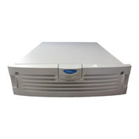
Nortel Contivity 1740 Install Manual (218 pages)
VPN Router
Brand:
Nortel
| Category:
Network Router
| Size: 2.89 MB
Table of Contents
Statement of Conditions
2
Table of Contents
7
Features
17
1000BASE-T (1000 GT) Ethernet Interface Card
17
New in this Release
17
Finding the Latest Updates on the Nortel Web Site
19
Getting Help from the Nortel Web Site
19
How to Get Help
19
Getting Help from a Specialist by Using an Express Routing Code
20
Getting Help over the Phone from a Nortel Solutions Center
20
Getting Help through a Nortel Distributor or Reseller
21
Preface
23
Acronyms
24
Before You Begin
24
Text Conventions
24
Related Publications
25
Printed Technical Manuals
27
Chapter 1 Nortel VPN Router 600 Option Installation
29
Shutting down the System to Add or Replace Hardware
30
Opening the Nortel VPN Router 600
30
Figure 1 Removing the Screws from the Bottom of the VPN Router 600
31
Figure 2 Removing the Chassis from the Steel Enclosure
32
Figure 3 Nortel VPN Router 600 System Board
33
Installing or Replacing an Option Card
34
Table 1 Supported Option Cards for the Nortel VPN Router 600
34
Figure 4 Removing the Blank Bracket from the Option Card Slot
36
Figure 5 Inserting the Option Card
37
Figure 6 Securing the Option Card in the Slot
38
Figure 7 Replacing the Chassis in the Steel Enclosure
38
Replacing a DIMM
39
Figure 8 Installing a DIMM
41
Chapter 2 Nortel VPN Router 1100 Option Installation
43
Table 2 Supported Option Cards for the Nortel VPN Router 1100
43
Installing or Replacing Option Cards
44
Figure 9 Nortel VPN Router 1100 System Board
45
Chapter 3 Nortel VPN Router 1700 and 1600 Option Installation
49
Shutting down the System to Add or Replace Hardware
50
Removing the Front Bezel and Top Cover
51
Figure 10 Removing the Front Bezel
51
Figure 11 Removing the Top Cover
53
Figure 12 Location of Option Card Slots and Dimms on the System Board
54
Attaching the Antistatic Wrist Strap
55
Figure 13 Location of the Grounding Jack for the Antistatic Wrist Strap
55
Installing or Replacing Option Cards
56
Table 3 Supported Option Cards for the Nortel VPN Router 1600 and 1700
56
Table 4 Supported Option Cards for the Nortel VPN Router 1600
58
Figure 14 Removing an Option Card or a Filler Panel
59
Figure 15 Installing an Option Card
60
Installing or Replacing Dimms
61
Figure 16 Replacing the Front Bezel
61
Figure 17 Installing or Removing a DIMM in a Nortel VPN Router 1700 or 1600
63
Chapter 4 Nortel VPN Router 1740 Option Installation
65
Chapter 7 Nortel VPN Router 2750 Option Installation. . . . . . . . . . . . . . . . . . . . . . . . 113
66
Shutting down the System to Add or Replace Hardware
66
Removing the Front Bezel and Top Cover
67
Figure 18 Removing the Front Bezel
67
Figure 19 Removing the Top Cover
68
Figure 20 Location of Option Card and DIMM Slots on the System Board
69
Attaching the Antistatic Wrist Strap
70
Figure 21 Location of the Grounding Jack for the Antistatic Wrist Strap
70
Installing or Replacing Option Cards
71
Table 5 Supported Option Cards for the Nortel VPN Router 1740
71
Installing or Replacing an Option Card
72
Installing the SSL VPN Module 1000 with Other Option Cards
72
Figure 22 Installing or Removing an Option Card
74
Figure 23 Replacing the Front Bezel
75
Installing or Replacing Dimms
76
Figure 24 Installing or Removing a DIMM
78
Chapter 5 Nortel VPN Router 1750 Option Installation
81
Shutting down the System to Add or Replace Hardware
82
Removing the Front Bezel and Top Cover
83
Figure 25 Removing the Front Bezel
83
Figure 26 Removing the Top Cover
85
Figure 27 Location of Option Card and DIMM Slots on the System Board
86
Attaching the Antistatic Wrist Strap
87
Figure 28 Location of the Grounding Jack for the Antistatic Wrist Strap
87
Installing or Replacing Option Cards
88
Table 6 Supported Option Cards for the Nortel VPN Router 1750
88
Installing the SSL VPN Module 1000 with Other Option Cards
89
Installing or Replacing an Option Card
90
Figure 29 Installing or Removing an Option Card
91
Installing or Replacing Dimms
92
Figure 30 Replacing the Front Bezel
92
Figure 31 Installing or Removing a DIMM
94
Chapter 6 Nortel VPN Router 2700 and 2600 Option Installation
97
Shutting down the System to Add or Replace Hardware
98
Figure 32 Removing the Front Bezel
99
Removing the Front Bezel and Top Cover
99
Figure 33 Removing the Top Cover
100
Figure 34 Location of Option Card Slots and Dimms on the System Board
101
Figure 35 Location of the Grounding Jack for the Antistatic Wrist Strap
102
Table 7 Supported Option Cards for the Nortel VPN Router 2600 and 2700
103
Table 8 Installing Other Option Cards with the SSL VPN Module 1000
104
Table 9 Supported Option Cards for the Nortel VPN Router 2600
105
Figure 36 Installing or Removing an Option Card
107
Figure 37 Replacing the Front Bezel
108
Table 10 Base and Maximum Memory for the Nortel VPN Router 2600 and 2700
109
Installing or Replacing Dimms
109
Figure 38 Installing or Removing a DIMM
111
Shutting down the System to Add or Replace Hardware
114
Figure 39 Removing the Front Bezel
115
Removing the Front Bezel and Top Cover
115
Figure 40 Removing the Top Cover
117
Figure 41 Location of Option Card and DIMM Slots on the System Board
118
Figure 42 Location of the Grounding Jack for the Antistatic Wrist Strap
119
Table 11 Supported Option Cards for the Nortel VPN Router 2750
120
Table 12 Installing Other Option Cards with the SSL VPN Module 1000
121
Installing or Replacing an Option Card
122
Figure 43 Installing or Removing an Option Card
123
Figure 44 Replacing the Front Bezel
124
Installing or Replacing Dimms
124
Figure 45 Installing or Removing a DIMM
126
Chapter 8 Nortel VPN Router 4600 Option Installation
129
Opening the VPN Router 4600
130
Figure 46 Removing the Nortel VPN Router 4600 Front Bezel
131
Figure 47 Nortel VPN Router 4600 Front Components
132
Nortel VPN Router 4600 System Board Layout
133
Figure 48 Sample Nortel VPN Router 4600 System Board
133
Installing or Replacing Option Cards
134
Table 13 Supported Option Cards for the Nortel VPN Router 4600
134
Figure 49 Installing Nortel VPN Router 4600 Option Cards
136
Installing or Replacing Dimms
137
Replacing a Power Supply
138
Figure 50 Installing Nortel VPN Router 4600 Dimms
138
Figure 51 Removing a Nortel VPN Router 4600 Power Supply
139
Replacing a Hard Disk Drive
140
Figure 52 Removing a Nortel VPN Router 4600 Hard Disk Drive
141
Chapter 9 Nortel VPN Router 5000 Option Installation
143
Preparing to Install Hardware Options
145
Option Cards, Dimms, and Fan Trays
145
Power Supplies
145
Hard Disk Drives
145
Shutting down the System to Add or Replace Hardware
146
Removing the Front Bezel and Top Cover
147
Figure 53 Removing the Front Bezel
148
Figure 54 Removing the Top Cover
149
Figure 55 Location of Option Cards, Dimms, and Fan Trays on the System Board
150
Attaching the Antistatic Wrist Strap
151
Figure 56 Location of the Grounding Jack for the Antistatic Wrist Strap
151
Figure 57 Nortel VPN Router 5000 Option Card Slots and Buses
152
Table 14 Supported Option Cards for the Nortel VPN Router 5000
153
Table 15 Optimal Placement of Option Cards in the Nortel VPN Router 5000
154
Figure 58 Flowchart for Option Card Installation in the Nortel VPN Router 5000
156
Installing or Replacing Option Cards
157
Support for 16 I/O Ports
157
Installing or Replacing an Option Card
157
Figure 59 Installing or Removing an Option Card
158
Figure 60 Replacing the Front Bezel
159
Installing or Replacing Dimms
160
Considerations for Installing Dimms
160
Figure 61 DIMM Memory Banks on the Nortel VPN Router 5000 Motherboard
160
Figure 62 DIMM Label: Example 1
161
Figure 63 DIMM Label: Example 2
161
Installing Dimms
162
Figure 64 Installing or Removing a DIMM
163
Replacing a Power Supply
164
Table 16 Model Number for each Chassis that Supports Either the 350-Watt or 500-Watt Power Supply
165
Figure 65 Location of the Nortel VPN Router 5000 and Nortel VPN Router 5000E Power Supplies (Rear of the Chassis)
166
Figure 66 Removing a Power Supply
167
Replacing a Hard Disk Drive
168
Figure 67 Inserting a Power Supply
168
Figure 68 Location of the Nortel VPN Router 5000 Hard Disk Drives
169
Figure 69 Removing a Hard Disk Drive
171
Figure 70 Inserting a Hard Disk Drive
172
Replacing a Fan Tray
173
Figure 71 Location of the Nortel VPN Router 5000 Fan Trays
173
Figure 72 Removing a Fan Tray
175
Figure 73 Installing a Fan Tray
176
Appendix A Technical Specifications
179
VPN Router Security Accelerator
181
Figure 74 VPN Router Security Accelerator Card
181
SSL VPN Module 1000
182
Figure 75 SSL VPN Module 1000
182
10/100BASE-TX Ethernet Interface Card
183
Figure 76 10/100BASE-TX Ethernet Interface Card (All Models Except VPN Router 1100)
183
Figure 77 10/100BASE-TX Ethernet Interface Card (for the VPN Router 1100 Only)
183
Table 17 10/100BASE-TX Ethernet Port Pinouts (All Models Except VPN Router 1100)
184
Table 18 10/100BASE-TX Ethernet Port Pinouts (VPN Router 1100 Only)
184
1000BASE-T (1000 GT) Ethernet Interface Card
185
Figure 78 1000BASE-T (1000 GT) Ethernet Interface Card (All Models Except VPN Router 1100)
186
Figure 79 VPN Router 1100 Full-Height 1000BASE-T (1000 GT)
186
Figure 80 VPN Router 1100 Half-Height 1000BASE-T (1000 GT)
187
Table 19 1000BASE-T (1000 GT) Ethernet Pinouts
187
1000BASE-T (1000 MT) Ethernet Interface Card
188
Figure 81 1000BASE-T (1000 MT) Ethernet Interface Card
188
1000BASE-SX Ethernet Interface Card
189
Figure 82 1000BASE-SX Ethernet Interface Card
189
Table 20 1000BASE-T Ethernet Port Pinouts
189
56/64K CSU/DSU WAN Interface Card
190
Figure 83 56/64K CSU/DSU WAN Interface Card
190
Figure 84 56/64K CSU/DSU WAN Interface Card (for the VPN Router 1100 Only)
190
Table 21 56/64K CSU/DSU Cable Pinouts for Crossover Connection
191
ADSL WAN Interface Card
192
Figure 85 ADSL WAN Interface Card
192
Table 22 56/64K CSU/DSU Cable Pinouts for Straight-Through Connection
192
Figure 86 ADSL WAN Interface Card (for the VPN Router 1100 Only)
193
Table 23 ADSL Annex a Cable Pinouts
193
Table 24 ADSL Annex B Cable Pinouts
193
ISDN BRI Interface Card
194
Figure 87 ISDN BRI S/T Interface Card or ISDN BRI U Interface Card
194
Figure 88 ISDN BRI S/T Interface Card (for the VPN Router 1100 Only)
194
Figure 89 ISDN BRI U Interface Card (for the VPN Router 1100 Only)
194
Table 25 ISDN BRI S/T Cable Pinouts
195
Table 26 ISDN BRI U Cable Pinouts
195
T1/E1 CSU/DSU WAN Interface Card
196
Figure 90 T1/E1 CSU/DSU WAN Interface Card (Half-Height Card)
196
Figure 91 T1/E1 CSU/DSU WAN Interface Card (Full-Height Card)
196
Figure 92 T1/E1 CSU/DSU WAN Interface Card (for the VPN Router 1100)
196
Table 27 T1/E1 CSU/DSU Cable Pinouts for Crossover Connection
197
Quad T1/E1 CSU/DSU WAN Interface Card
198
Figure 93 Quad T1/E1 CSU/DSU WAN Interface Card
198
Table 28 T1/E1 CSU/DSU Cable Pinouts for Straight-Through Connection
198
V.90 Modem Interface Card
199
Single V.35/X.21 WAN Interface Card
200
Figure 94 V.90 Modem Interface Card
200
Figure 95 V.90 Modem Interface Card (for the VPN Router 1100 Only)
200
Table 29 V.90 Modem Cable Pinouts
200
Figure 96 Single V.35/X.21 WAN Interface Card (Full-Height Card)
201
Figure 97 Single V.35/X.21 WAN Interface Card (Half-Height Card)
201
Figure 98 Single V.35/X.21 WAN Interface Card
201
Table 30 V.35 Cable Pinouts
202
Table 31 X.21 Cable Pinouts
203
Table 32 RS-232 DTE Cable Pinout
204
Table 33 RS-232 SDLC Cable Pinouts
205
Table 34 V.35 SDLC Cable Pinouts
207
HSSI WAN Interface Card
208
Figure 99 HSSI WAN Interface Card
208
Table 35 T3 Cable Pinouts
208
External Modem Adapter for the Nortel VPN Router 1010/1050/1100
210
Figure 100 Serial Cable Adapter for Connection to Modem (DB9-To-DB25)
210
Table 36 Null Modem Adapter Cable Pinouts
211
Index
213
Advertisement
Nortel Contivity 1740 Installing (158 pages)
Hardware Options for the Contivity Secure IP Services Gateway
Brand:
Nortel
| Category:
Switch
| Size: 2.5 MB
Table of Contents
Table of Contents
7
Preface
17
Before You Begin
17
Text Conventions
18
Acronyms
18
Related Publications
19
How to Get Help
21
Contivity 600 Option Installation
23
Shutting down the System to Add or Replace Hardware
24
Opening the Contivity 600
24
Figure 1 Removing the Screws from the Bottom of the Contivity 600
25
Figure 2 Removing the Chassis from the Steel Enclosure
26
Figure 3 Contivity 600 System Board
27
Installing and Replacing an Option Card
28
Figure 4 Removing the Blank Bracket from the Option Card Slot
29
Figure 5 Inserting the Option Card
30
Figure 6 Securing the Option Card in the Slot
31
Figure 7 Replacing the Chassis in the Steel Enclosure
31
Replacing a DIMM
32
Figure 8 Installing a DIMM
33
Contivity 1100 Option Installation
35
Table 1 Supported Option Cards for the Contivity 1100
35
Figure 9 Contivity 1100 System Board
37
Contivity 1700 and 1600 Option Installation
39
Shutting down the System to Add or Replace Hardware
40
Removing the Front Bezel and Top Cover
41
Figure 10 Removing the Front Bezel
41
Figure 11 Removing the Top Cover
42
Figure 12 Location of Option Card Slots and Dimms on the System Board
43
Attaching the Antistatic Wrist Strap
44
Figure 13 Location of the Grounding Jack for the Antistatic Wrist Strap
44
Installing and Replacing Option Cards
45
Table 2 Supported Option Cards for the Contivity 1700
45
Table 3 Supported Option Cards for the Contivity 1600
45
Figure 14 Removing an Option Card or a Filler Panel
47
Figure 15 Installing an Option Card
48
Installing and Replacing Dimms
49
Figure 16 Replacing the Front Bezel
49
Figure 17 Installing and Removing a DIMM in a Contivity 1700 or 1600
51
Figure
51
Contivity 1740 Option Installation
53
Shutting down the System to Add or Replace Hardware
54
Removing the Front Bezel and Top Cover
55
Figure 18 Removing the Front Bezel
55
Figure 19 Removing the Top Cover
56
Figure 20 Location of Option Card and DIMM Slots on the System Board
57
Attaching the Antistatic Wrist Strap
58
Figure 21 Location of the Grounding Jack for the Antistatic Wrist Strap
58
Installing and Replacing Option Cards
59
Table 4 Supported Option Cards for the Contivity 1740
59
Figure 22 Installing and Removing an Option Card
61
Figure 23 Replacing the Front Bezel
62
Installing and Replacing Dimms
63
Figure 24 Installing and Removing a DIMM
64
Contivity 2700 and 2600 Option Installation
67
Shutting down the System to Add or Replace Hardware
68
Removing the Front Bezel and Top Cover
69
Figure 25 Removing the Front Bezel
69
Figure 26 Removing the Top Cover
70
Figure 27 Location of Option Card Slots and Dimms on the System Board
71
Attaching the Antistatic Wrist Strap
72
Figure 28 Location of the Grounding Jack for the Antistatic Wrist Strap
72
Installing and Replacing Option Cards
73
Table 5 Supported Option Cards for the Contivity 2700
73
Table 6 Supported Option Cards for the Contivity 2600
74
Figure 29 Installing and Removing an Option Card
75
Installing and Replacing Dimms
77
Table 7 Base and Maximum Memory for the Contivity 2600 and 2700
77
Contivity 4500 Option Installation
81
Opening the Contivity 4500
81
Figure 33
83
Contivity 4500 System Board Layout
84
Installing and Replacing Option Cards
86
Table 8 Supported Option Cards for the Contivity 4500
86
Installing and Replacing Dimms
88
Replacing a Power Supply
90
Figure 37
90
Replacing a Hard Disk Drive
91
Figure
91
Contivity 4600 Option Installation
93
Opening the Contivity 4600
93
Contivity 4600 System Board Layout
96
Installing and Replacing Option Cards
97
Table 9 Supported Option Cards for the Contivity 4600
97
Installing and Replacing Dimms
99
Figure
99
Replacing a Power Supply
100
Figure
100
Replacing a Hard Disk Drive
102
Contivity 5000 Option Installation
105
Preparing to Install Hardware Options
106
Option Cards, Dimms, and Fan Trays
106
Power Supplies
106
Removing the Front Bezel
108
Removing the Top Cover
110
Table 10 Supported Option Cards for the Contivity 5000
113
Replacing the Front Bezel
116
Removing a Power Supply
121
Removing a Hard Disk Drive
124
Removing a Fan Tray
127
10/100BASE Ethernet Interface Card
133
Table 11 10/100BASE Ethernet Port Pinouts (All Models Except Contivity 1100)
134
Table 12 10/100BASE Ethernet Port Pinouts (Contivity 1100 Only)
134
1000BASE-T Ethernet Interface Card
135
1000BASE-SX Ethernet Interface Card
136
Table 13 1000BASE-T Ethernet Port Pinouts
136
Figures
137
Figure 65 ADSL WAN Interface Card
137
Figure 66 ISDN BRI S/T Interface Card
138
Figure 67 ISDN BRI U Interface Card
138
Table 14 ADSL Cable Pinouts
138
Table 15 ISDN BRI S/T Cable Pinouts
139
Table 16 ISDN BRI U Cable Pinouts
139
Figure 68 T1/E1 CSU/DSU WAN Interface Card
140
Table 17 T1/E1 CSU/DSU Cable Pinouts for Crossover Connection
141
Table 18 T1/E1 CSU/DSU Cable Pinouts for Straight-Through Connection
141
Figure 69 Quad T1/E1 CSU/DSU WAN Interface Card
142
Figure 70 V.90 Modem Interface Card
143
Figure 71 Single V.35/X.21 WAN Interface Card
143
Table 19 V.90 Modem Cable Pinouts
143
Table 20 V.35 Cable Pinouts
144
Table 21 X.21 Cable Pinouts
145
Figure 72 Dual V.35 WAN Interface Card
147
Table 22 DB26-To-V.35 Cable Pinouts
148
Figure 73 HSSI WAN Interface Card
149
Table 23 T3 Cable Pinouts
149
Figure 74 Serial Cable Adapter for Connection to Modem (DB9-To-DB25)
151
Table 24 Null Modem Adapter Cable Pinouts
152
NORTEL Contivity 1740 Installing Manual (94 pages)
Brand:
NORTEL
| Category:
Network Router
| Size: 2.4 MB
Table of Contents
Table of Contents
7
Installing the Contivity 1700
11
Installing the Contivity 1700
13
Before You Begin
15
Preface
15
Acronyms
16
Text Conventions
16
Related Publications
17
How to Get Help
18
Chapter 1 Installing the Contivity 1700 Chassis
19
Description of the Contivity 1700
19
Preparing to Install the Contivity 1700
20
Figure 1 Front View of the Contivity 1700
20
Shipment Contents
21
Table 1 Items Shipped with the Contivity 1700
21
Additional Equipment
22
Cables
22
Hardware for Mounting the Chassis in an Equipment Rack
22
Site Requirements
22
Installing the Chassis
23
Installing the Chassis on a Flat Surface
23
Figure 2 Placement of Rubber Feet on the Bottom of the Chassis
23
Installing the Chassis in an Equipment Rack
24
Rack-Mount Recommendations
24
Attaching the Shelf in the Equipment Rack
24
Figure 3 Attaching the Cage Nuts to the Rack
25
Figure 4 Installing the Shelf in the Equipment Rack
25
Installing the Contivity 1700
25
Mounting the Chassis in the Equipment Rack
26
Figure 5 Removing the Front Bezel
26
Figure 6 Replacing the Front Bezel
27
Chapter 2 Cabling the Gateway and Turning the Power on
29
Connecting Communications Cables
30
Table 2 Interfaces and Cables for the Contivity 1700
30
Figure 7 Rear View of the Contivity 1700
31
Connecting the Power Cord
32
Table 3 Power Cord Requirements
32
Verifying a Successful Installation
33
Understanding the Leds
34
Front Panel Leds
34
Figure 8 Front Panel Leds
34
Table 4 Front Panel LED Indicators
34
Leds on the System 10/100BASE Ethernet Port
35
Figure 9 Leds on the System 10/100BASE Ethernet Port
35
Table 5 LED Indicators on the System 10/100BASE Ethernet Port
35
Installing the Contivity
35
10/100BASE Ethernet Interface Card Leds
36
Figure 10 Leds on the 10/100BASE Ethernet Interface Card
36
Table 6 LED Indicators on the 10/100BASE Ethernet Interface Card
36
56/64K CSU/DSU WAN Interface Card Leds
37
Figure 11 Leds on the 56/64K CSU/DSU WAN Interface Card
37
Table 7 LED Indicators on the 56/64K CSU/DSU WAN Interface Card
37
ADSL WAN Interface Card Leds
38
Figure 12 Leds on the ADSL WAN Interface Card
38
Table 8 LED Indicators on the ADSL WAN Interface Card
38
T1/E1 CSU/DSU WAN Interface Card Leds
39
Figure 13 Leds on the T1/E1 CSU/DSU WAN Interface Card
39
Table 9 LED Indicators on the T1/E1 CSU/DSU WAN Interface Card
39
Quad T1/E1 CSU/DSU WAN Interface Card Leds
40
Figure 14 Leds on the Quad T1/E1 CSU/DSU WAN Interface Card
40
Table 10 LED Indicators on the Quad T1/E1 CSU/DSU WAN Interface Card
40
Single V.35/X.21 WAN Interface Card Leds
41
Figure 15 Leds on the Single V.35/X.21 WAN Interface Card
41
Table 11 LED Indicators on the Single V.35/X.21 WAN Interface Card
41
Chapter 3 Configuring the Management IP Interface
43
Required Information
44
Configuring the Management IP Address
45
Installing the Contivity 1700
47
Testing the Configuration
49
Figure 16 Welcome Screen
50
Troubleshooting
51
Chapter 4 Installing Option Cards and Dimms
53
Shutting down the System to Add or Replace Hardware
54
Removing the Front Bezel and Top Cover
55
Figure 17 Removing the Front Bezel
55
Figure 18 Removing the Top Cover
56
Figure 19 Location of Option Card Slots and Dimms on the System Board
57
Installing the Contivity 1700
57
Attaching the Antistatic Wrist Strap
58
Figure 20 Location of the Grounding Jack for the Antistatic Wrist Strap
58
Installing and Replacing Option Cards
59
Table 12 Supported Option Cards for the Contivity 1700
59
Figure 21 Removing an Option Card or a Filler Panel
61
Installing the Contivity 1700
61
Figure 22 Installing an Option Card
62
Figure 23 Replacing the Front Bezel
63
Installing the Contivity 1700
63
Installing and Replacing Dimms
64
Figure 24 Installing and Removing a DIMM
65
Appendix A Technical Specifications
67
Chassis Specifications
67
Table 13 Physical, Electrical, and Environmental Specifications
67
System Ports
68
10/100BASE Ethernet LAN Port
68
Figure 25 10/100BASE Ethernet Connector
68
Serial Port
69
Table 14 10/100BASE Ethernet Port Pinouts
69
Table 15 Multiple DB9 and DB25 Connector Pinouts
69
Modem Cable Specifications
70
Figure 26 Modem Cable (9-Pin D-Sub Plug to RS-232-C Modem Plug)
70
Table 16 Modem Cable Pinouts
70
Hardware Option Cards
71
Hardware Accelerator Card
71
10/100BASE Ethernet Interface Card
72
56/64K CSU/DSU WAN Interface Card
72
Figure 27 10/100BASE Ethernet Interface Card
72
Figure 28 56/64K CSU/DSU WAN Interface Card
72
Table 17 56/64K CSU/DSU Cable Pinouts for Crossover Connection
73
Installing the Contivity 1700
73
ADSL WAN Interface Card
74
Figure 29 ADSL WAN Interface Card
74
Table 18 56/64K CSU/DSU Cable Pinouts for Straight-Through Connection
74
ISDN BRI Interface Card
75
Figure 30 ISDN BRI S/T Interface Card
75
Figure 31 ISDN BRI U Interface Card
75
Table 19 ADSL Cable Pinouts
75
Table 20 ISDN BRI S/T Cable Pinouts
76
Table 21 ISDN BRI U Cable Pinouts
76
T1/E1 CSU/DSU WAN Interface Card
77
Figure 32 T1/E1 CSU/DSU WAN Interface Card
77
Table 22 T1/E1 CSU/DSU Cable Pinouts for Crossover Connection
78
Table 23 T1/E1 CSU/DSU Cable Pinouts for Straight-Through Connection
78
Quad T1/E1 CSU/DSU WAN Interface Card
79
Figure 33 Quad T1/E1 CSU/DSU WAN Interface Card
79
V.90 Modem Interface Card
80
Single V.35/X.21 WAN Interface Card
80
Figure 34 V.90 Modem Interface Card
80
Figure 35 Single V.35/X.21 WAN Interface Card
80
Table 24 V.90 Modem Cable Pinouts
80
Table 25 V.35 Cable Pinouts
81
Installing the Contivity 1700
81
Table 26 X.21 Cable Pinouts
82
Installing the Contivity 1700
83
Dual V.35 WAN Interface Card
84
Figure 36 Dual V.35 WAN Interface Card
84
Table 27 DB26-To-V.35 Cable Pinouts
85
Installing the Contivity 1700
85
HSSI WAN Interface Card
86
Figure 37 HSSI WAN Interface Card
86
Table 28 T3 Cable Pinouts
86
Installing the Contivity 1700
87
Index
89
Advertisement
Nortel Contivity 1740 Installing (96 pages)
Brand:
Nortel
| Category:
Network Hardware
| Size: 1.14 MB
Table of Contents
Table of Contents
7
Preface
15
Before You Begin
15
Text Conventions
16
Acronyms
16
Related Publications
17
How to Get Help
18
Installing the Contivity 1740 Chassis
19
Description of the Contivity 1740
19
Preparing to Install the Contivity 1740
20
Figure 1 Front View of the Contivity 1740
20
Shipment Contents
21
Table 1 Items Shipped with the Contivity 1740
21
Additional Equipment
22
Cables
22
Hardware for Mounting the Chassis in an Equipment Rack
22
Site Requirements
22
Installing the Chassis
23
Installing the Chassis on a Flat Surface
23
Figure 2 Placement of Rubber Feet on the Bottom of the Chassis
23
Installing the Chassis in an Equipment Rack
24
Rack-Mount Recommendations
24
Attaching the Shelf in the Equipment Rack
24
Figure 3 Attaching the Cage Nuts to the Rack
25
Figure 4 Installing the Shelf in the Equipment Rack
25
Mounting the Chassis in the Equipment Rack
26
Figure 5 Removing the Front Bezel
26
Figure 6 Replacing the Front Bezel
27
Cabling the Gateway and Turning the Power on
29
Connecting Communications Cables
30
Table 2 Interfaces and Cables for the Contivity 1740
30
Figure 7 Rear View of the Contivity 1740
31
Connecting the Power Cord
32
Table 3 Power Cord Requirements
32
Verifying a Successful Installation
33
Understanding the Leds
34
Front Panel Leds
34
Figure 8 Front Panel Leds
34
Table 4 Front Panel LED Indicators
34
Leds on the System 10/100BASE Ethernet Port
35
Figure 9 Leds on the System 10/100BASE Ethernet Port
35
Table 5 LED Indicators on the System 10/100BASE Ethernet Port
35
10/100BASE Ethernet Interface Card Leds
36
1000BASE-T Ethernet Interface Card Leds
36
Figure 10 Leds on the 10/100BASE Ethernet Interface Card
36
Figure 11 Leds on the 1000BASE-T Ethernet Interface Card
36
Table 6 LED Indicators on the 10/100BASE Ethernet Interface Card
36
1000BASE-SX Ethernet Interface Card Leds
37
Figure 12 Leds on the 1000BASE-SX Ethernet Interface Card
37
Table 7 LED Indicators on the 1000BASE-T Ethernet Interface Card
37
Table 8 LED Indicators on the 1000BASE-SX Ethernet Interface Card
37
ADSL WAN Interface Card Leds
38
Figure 13 Leds on the ADSL WAN Interface Card
38
Table 9 LED Indicators on the ADSL WAN Interface Card
38
T1/E1 CSU/DSU WAN Interface Card Leds
39
Figure 14 Leds on the T1/E1 CSU/DSU WAN Interface Card
39
Table 10 LED Indicators on the T1/E1 CSU/DSU WAN Interface Card
39
Quad T1/E1 CSU/DSU WAN Interface Card Leds
40
Figure 15 Leds on the Quad T1/E1 CSU/DSU WAN Interface Card
40
Table 11 LED Indicators on the Quad T1/E1 CSU/DSU WAN Interface Card
40
Single V.35/X.21 WAN Interface Card Leds
41
Figure 16 Leds on the Single V.35/X.21 WAN Interface Card
41
Table 12 LED Indicators on the Single V.35/X.21 WAN Interface Card
41
Configuring the Management IP Interface
43
Required Information
44
Using the IP Address Configuration Utility
44
System Requirements
44
Running the IP Address Configuration Utility
45
Figure 17 Icon for the IP Address Configuration Utility
45
Figure 18 IP Address Configuration Utility Dialog Box
46
Using the Serial Interface
47
Testing the Configuration
51
Figure 19 Welcome Screen
52
Troubleshooting
53
Installing Option Cards and Dimms
55
Shutting down the System to Add or Replace Hardware
56
Removing the Front Bezel and Top Cover
57
Figure 20 Removing the Front Bezel
57
Figure 21 Removing the Top Cover
58
Figure 22 Location of Option Card and DIMM Slots on the System Board
59
Attaching the Antistatic Wrist Strap
60
Figure 23 Location of the Grounding Jack for the Antistatic Wrist Strap
60
Installing and Replacing Option Cards
61
Table 13 Supported Option Cards for the Contivity 1740
61
Figure 24 Installing and Removing an Option Card
63
Figure 25 Replacing the Front Bezel
64
Installing and Replacing Dimms
65
Figure 26 Installing and Removing a DIMM
66
Technical Specifications
69
Chassis Specifications
69
Table 14 Physical, Electrical, and Environmental Specifications
69
System Ports
70
10/100BASE Ethernet LAN Port
70
Figure 27 10/100BASE Ethernet Connector
70
Serial Port
71
Table 15 10/100BASE Ethernet Port Pinouts
71
Table 16 Multiple DB9 and DB25 Connector Pinouts
71
Modem Cable Specifications
72
Figure 28 Modem Cable (9-Pin D-Sub Plug to RS-232-C Modem Plug)
72
Table 17 Modem Cable Pinouts
72
Hardware Option Cards
73
Contivity Security Accelerator (CSA) and Hardware Accelerator Cards
73
10/100BASE Ethernet Interface Card
74
Figure 29 10/100BASE Ethernet Interface Card
74
1000BASE-T Ethernet Interface Card
75
Figure 30 1000BASE-T Ethernet Interface Card
75
1000BASE-SX Ethernet Interface Card
76
Figure 31 1000BASE-SX Ethernet Interface Card
76
Table 18 1000BASE-T Ethernet Port Pinouts
76
ADSL WAN Interface Card
77
Figure 32 ADSL WAN Interface Card
77
ISDN BRI Interface Card
78
Figure 33 ISDN BRI S/T Interface Card
78
Figure 34 ISDN BRI U Interface Card
78
Table 19 ADSL Cable Pinouts
78
Table 20 ISDN BRI S/T Cable Pinouts
79
Table 21 ISDN BRI U Cable Pinouts
79
T1/E1 CSU/DSU WAN Interface Card
80
Figure 35 T1/E1 CSU/DSU WAN Interface Card
80
Table 22 T1/E1 CSU/DSU Cable Pinouts for Crossover Connection
81
Table 23 T1/E1 CSU/DSU Cable Pinouts for Straight-Through Connection
81
Quad T1/E1 CSU/DSU WAN Interface Card
82
Figure 36 Quad T1/E1 CSU/DSU WAN Interface Card
82
Single V.35/X.21 WAN Interface Card
83
Figure 37 Single V.35/X.21 WAN Interface Card
83
Table 24 V.35 Cable Pinouts
83
Table 25 X.21 Cable Pinouts
85
Dual V.35 WAN Interface Card
86
Figure 38 Dual V.35 WAN Interface Card
86
Table 26 DB26-To-V.35 Cable Pinouts
87
HSSI WAN Interface Card
88
Figure 39 HSSI WAN Interface Card
88
Table 27 T3 Cable Pinouts
88
V.90 Modem Interface Card
90
Figure 40 V.90 Modem Interface Card
90
Table 28 V.90 Modem Cable Pinouts
90
Index
91
Nortel Contivity 1740 Product Support Bulletin (3 pages)
Nortel 1700: Product Support Bulletin
Brand:
Nortel
| Category:
Network Router
| Size: 0.12 MB
Advertisement
Related Products
Nortel 114200-E
Nortel 1000ASE-XD
Nortel 10292FA
Nortel 10396EA
Nortel 1500 Series
Nortel 1700
Nortel Contivity VPN Switch 1010
Nortel Accelar 1050
Nortel Contivity 110
Nortel Contivity 1100
Nortel Categories
IP Phone
Telephone
Switch
Software
Server
More Nortel Manuals
Login
Sign In
OR
Sign in with Facebook
Sign in with Google
Upload manual
Upload from disk
Upload from URL