Table of Contents
Advertisement
Advertisement
Chapters
Table of Contents

Related Manuals for KEP MMI-1500


Summary of Contents for KEP MMI-1500
- Page 1 MMI-TS MMI-1500, MMI-850, MMI-750, MMI-730 Installation & Operations Manual, Software Reference, and Connection Guide Version 2.7.0 Kessler Ellis Products 10 Industrial Way East Eatontown, NJ 07724 Phone: 732-935-1320 Fax: 732-935-9344 www.kep.com 99676REV20JAN06 $70.00...
-
Page 3: About This Manual
About this Manual This document is based on information available at the time of its publication. While efforts have been made to be accurate, the information in this document may not cover all details or variations in hardware or software, nor does it provide for every possibility concerning installation, operation, or maintenance. Features may be described herein which are not present in all hardware. - Page 4 This manual is designed to provide the necessary information for trouble-free installation and operation of HMI Touchscreens. Additional help is available when accessing the help functions in the EasyBuilder software. If further assistance is needed, please call KEP at 1-800-631-2165 or visit our web site at www.kep.com.
- Page 5 PROPRIETARY NOTICE The information contained in this publication is derived in part from proprietary and patent data. This information has been prepared for the expressed purpose of assisting operating and maintenance personnel in the efficient use of the instrument described herein. Publication of this information does not convey any rights to use or reproduce or to use it for any purpose other than in connection with the installation, operation and maintenance of the equipment described herein.
-
Page 6: Table Of Contents
About this Manual............iii 6.8 Offline-Simulator...........25 Text Construction ............iii 6.9 Download .............25 Safety Instructions ............iv 6.10 Upload..............25 WARRANTY............. v 6.11 Mode Change.............26 7.0 Software Fundamentals ...........27 Section 1: Installation and Startup Guide ......1 7.1 Screen Editor Overview........27 1.0 Getting Started ............1 7.1.1 Changing Screen Appearance.......28 1.1 The MMI-Touchscreen Series........ - Page 7 7.9.5 System Reserved Retentive Word Usage with 12.0 Project Management and Documenting a Project 114 Security ..............80 12.1 Compressing/Uncompressing a project ... 114 7.9.6 How to Implement User Security....81 12.2 Decompiling a project ........115 7.9.7 Additional Security Through the PLC .... 81 12.3 Documenting a project ........
- Page 8 13.24 Alarm Scan ............ 173 16.13 IDEC OpenNET [PDS] ........231 13.25 System Message..........174 16.14 IIS ESC (INDUSTRIAL INDEXING SYSTEMS) 13.26 PLC Control ........... 174 .................232 13.26.1 Change Window ........175 16.15 Jetter Nano.............234 13.26.2 Back light control ........175 16.16 Keyence KV/Visual KV [PDS]......235 13.26.3 Screen hardcopy ........
-
Page 9: Section 1: Installation And Startup Guide
A personal computer with EasyBuilder programming Installation CD provided with each unit. software installed. Software is also available from the KEP website. (www.kep.com) A special PC to MMI programming cable is required MT5_PC cable ships with each unit. -
Page 10: Installation Instructions
2.0 Installation Instructions 2.1 Mounting Instructions 2.1.1 Location Considerations Care should be taken when locating equipment behind the unit to ensure that AC power wiring, PLC output modules, contactors, starters and relays, and any other source of electrical interference are located away from the back of the unit. Particular note should be taken to the position of variable speed drives and switching power supplies. -
Page 11: Environmental Considerations
7.56 [192] MMI-720 / MMI-730 / MMI-750 Models 5.43 7.56"(192mm) W x 5.43"(138mm) H [138] Put the unit through the panel cut out. Slide the clamps into the 4 or 6 holes provided around the NEMA-4 case. Tighten the clamping screws in an even pattern until the unit is secured in the panel. Mounting Panel Mounting clamp, 4or 6 places... -
Page 12: Power Connections
2.2 Power Connections Make sure that all local and national electrical standards are met when the installing the unit. Contact your local authorities to determine which codes apply. 2.2.1 Power Requirements The HMI can be powered by DC power only. The specified voltage range is +22 to 25 Power Volts DC. -
Page 13: Grounding Requirements
+24 VDC Wiring Diagrams Connection Use 18 AWG wire to connect positive DC line to the ‘+24V’ (DC+) terminal and the DC ground to the ‘0V‘ (-DC) terminal. See text below about FG ( Chassis Ground). Terminal Plug: (MMI-720, 730, 750 Models) To make a connection, strip about 3/8” of insulation off the end of the wire, and turn the connector screw counterclockwise until the gap is wide open. -
Page 14: Safety Guidelines
2.2.4 Safety Guidelines This section presents recommended installation practices, and procedures. Since no two applications are identical, these recommendations should be considered as guidelines. Hardware WARNING! The system designer should be aware that devices in Controller systems could fail and thereby Considerations create an unsafe condition. -
Page 15: Guide Lines For Eu Installations
The MMI Series has been designed to operate satisfactorily in electromagnetic noise (immunity) and without emitting high levels of electrical noise into the environment (emission). The units are designed to meet European Community standards when installed per the wiring instructions in this manual. Compatibility Standards The MMI has been designed to meet electromagnetic compatibility for industrial environments. -
Page 16: Communications Connections
Different cables are required for various devices. See Controller Reference Section for cable details. Cable The KEP part numbers have the SMIC prefix. Refer to a KEP catalog or data sheet for a complete Requirements listing of MMI compatible devices. -
Page 17: Connection To A Personal Computer
This port can be attached to a Computer via a special DB9 Female to DB9 Female cable provided Connection with the unit. (KEP P/N: MT5_PC) This port is activated automatically by the PC during: On line simulation, Download and Upload Port Activation activities. -
Page 18: Connection To A Printer
The printer port on the back of the unit is a Parallel printer port and is compatible with most printers that accept parallel connectors. The MMI-1500 and 850 models have printout capabilities. The printer port Print Out transmits data when a printable object is activated. - Page 19 2.4.5 HMI to HMI Connections The HMI supports a master - slave communications. One HMI is connected directly to the PLC and configured as the Master. All the other HMIs are connected in series to it and are configured as Slaves. In theory there is no limitation to the number of HMIs on a chain, however response time gradually decreases when more than three HMIs are linked together.
-
Page 20: Dip Switch Settings
It is recommended that the factory replacement of these components in case of their failure. Use our toll free number to contact KEP. Telephone: 1-800-631-2165. If the product must be returned, be sure to call KEP and get a Return Goods Authorization (RGA) number first. Units should be returned in their original packaging container, otherwise, any suitable rigid container can be used as a substitute. -
Page 21: Specifications
3.0 Specifications 3.1 General Specifications Specification Item Input power 21-25 VDC, 500 mA @ 24VDC Complies with EN50081-2 and EN50082-2 standards Complies with FCC Class A (Ferrite core required if using unshielded power supply wires) Isolation resistance Exceeds 50 MΩ at 500VDC Vibration endurance 10 to 25 Hz (X,Y,Z direction 2G 30 minutes) Protection structure... -
Page 22: Hardware Specification 750, 720 Models
3.3 Hardware Specification 750, 720 Models Item 750T / 750T-HB 730T LCD Display 5.7” TFT 256 color 5.7” STN 256 color 5.7” TFT 256 color 5.7” STN blue mode Contrast Ratio 60:1 30:1 150:1 15:1 Brightness cd/m2 Back light CCFLx1 MTBF 30,000 hr MTBF 30,000 hr MTBF 30,000 hr... -
Page 23: Trouble Shooting
4.0 Trouble Shooting 4.1 Power Problems Problems on power up: Unit does not light or unit lights but does not display any windows. 1. Check wiring for proper polarity. 2. Check power Supply for proper Voltage and Current capacity. 3. Check fuse. Problems during operation: Faulty unit operation may be due to problems with power quality. -
Page 24: Commonly Asked Questions
4.3 Commonly Asked Questions Q. Can I have multiple MMIs connected to one Controller? A. The ability to connect more than one HMI to a controller is accomplished through an HMI to HMI link. This is not done through any PLC protocol. It is done through the master-slave protocol of the MMI. Q. -
Page 25: Repairs And Returns
Use our toll free number to contact KEP if persistent problems are encountered. Telephone: 1-800-631-2165. If the product must be returned for any reason, be sure to call KEP and get a Return Goods Authorization (RGA) number first. Units should be returned in their original packaging container, otherwise, any suitable rigid container can be used as a substitute. - Page 26 Ethernet port (RJ-45) (only on some models) d. CF card slot (only on units with Ethernet ports) Reset Button Dip Switches Fuse Power Connections MMI-850, MMI-1500 Connection Points a. PLC[RS485]/PC[RS232]/AUX [RS485] b. PLC[RS232]/AUX [RS232] c. Ethernet port (RJ-45) d. CF card slot e. Printer port Fuse...
-
Page 27: Installing Easybuilder
Typical connection To Ethernet Port To PLC RS-232 Interface MT5_PC cable To PLC RS-485 Interface 5.2 Installing EasyBuilder ® ® Install EasyBuilder 500 on your PC. Software must be installed on a PC running Windows 98 , Windows 2000 or Windows ®... -
Page 28: Initial Start Up
5.3 Initial Start Up Use EasyManager to set the following: 1. COM Select Dropdown: Select the number of the RS232 Serial COM port for communications to the MMI. Ports COM1 through COM10 are available. 2. Click on EasyBuilder to start the screen editor for the MMI. Note: See the Software Reference section for further details about the EasyManager Application. -
Page 29: Creating A Project
4. Select the Display Mode…. Landscape Portrait 5. Select the Language Mode…. This setting determines the character set that is used in project development. Select Single Byte for European languages. These fonts are in the directory as Ascfont.8, Ascfont.16 and Ascfont.24. These represent the 8, 16 and 24 point sizes. - Page 30 Step 2. Select any additional Group, BMP and/or Shape Libraries to attach to the project. The default selection provides a good range of library objects. For a quick start, no additional libraries are needed. In the Library menu, select [Shape, Bitmap or Group] [Call up Library] or use the toolbar icons EasyBuilder provides three types of libraries.
- Page 31 Step 4. Save and Compile the project In the menu, select File|Save to save the project. In the menu select Tools|Compile… to compile the project. Step 5. Simulate the project either On-line or Off-line. Select Tool|On-line Simulation operation in the menu. After the project is complied, the Simulator retrieves data from the PLC through the unit and simulates operation.
-
Page 32: Section 2: Software Reference Guide
Section 2: Software Reference Guide 6.0 EasyManager Operations The EasyManager is a software shell for launching several utilities. Some functions are duplicated in the EasyBuilder screen-editing program. While the EasyBuilder program can be run as a stand-alone program, it is advised to run EasyManager first to set the COM port. -
Page 33: Online-Simulator
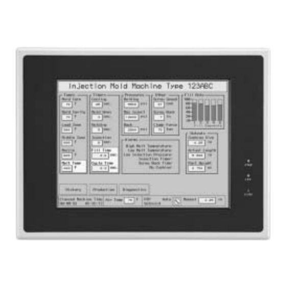
6.6 Online-Simulator The Online simulator retrieves data from the PLC through the unit and uses it to put a realistic image of the unit on the PC screen. The image shows how a project appears after download. Use the Online-Simulator to view demonstration projects and show how the windows look in actual operation. -
Page 34: Mode Change
Line 7: Indicates if Retentive (Recipe) memory is installed in the unit. (Old units may not have memory installed.) Line 8: Show the unit’s driver status. The unit should indicate that it accepts KEP drivers. If it does not, please contact the factory for assistance. -
Page 35: Software Fundamentals
7.0 Software Fundamentals 7.1 Screen Editor Overview Clicking on the Easy Manager’s [EasyBuilder] button causes the following window to appear. The functions of each screen area are explained below. a. Title Bar c. Library Tools e. State Selector g. Label Language b. -
Page 36: Changing Screen Appearance
7.1.1 Changing Screen Appearance The screen appearance can be changed to make project editing easier. This includes what toolbars are displayed, changing grid constraint properties and magnification. These changes affect the screen but do not change a window’s properties. 7.1.1.1 View Menu The View menu is used to Hide or show Toolbars, Status bar and Treebar. -
Page 37: System Parameters
Allow Function Key frame when making Shapes Checkbox: Enables/Disables the automatic creation of a shape using a function key assist. This is discussed further in the Library Operations Section. Jump to application mode when download done Checkbox: Enables/Disables automatically forcing the HMI to the application mode after a download. - Page 38 Use the MMI1500M selection to program the discontinued MMI1050. Use the MMI750T selection to program the MMI750T and MMI750T-HB. KEP recommends that you develop a project for its target hardware platform. (There is no utility to automatically resize a project for a larger or smaller screen.) Serial Port I/F: Select the PLC port’s type of hardware communications.
- Page 39 Baud rate, Parity, Data bits and Stop bits: Set the baud rate to match the PLC ports settings. These are disabled if Ethernet communication is selected. (Ethernet communication uses 10 BaseT and TCP/IP parameters.) Comm. delay and Additional Parameters: The Comm. Delay parameter is used for setting an interval between communications requests to the controller. Enter a number from 0 to 999.
- Page 40 HMI-HMI link speed: This is used only when a Serial interface is used for connecting multiple HMIs. Higher communication rates may cause faster window updates, but are diminished quicker by link distance and electrical interference. Note: All linked HMIs must be set to the same link speed. Slave units ignore the communication parameters associated with the PLC (Serial port I/F, Baud rate, Parity, etc.).
-
Page 41: The General Tab
7.2.2 The General Tab Task button The Task button is used to pop up the Fast Selection window or display the Task Bar. Minimized window’s icons are put on the Task Bar. This gives the project a familiar graphical user interface. Note: Refer to the Task Bar Operations section for a full description of the Task Button features. - Page 42 No. of windows: This setting is used to specify the maximum number of windows allowed open at any one time (1 - 6). The unit ignores attempts to open more windows than specified until an existing window is closed. When more windows are open than recommended, system resources may drop low enough to trigger a "System severe error"...
- Page 43 Common Window: Window 6 is the default common window. Objects placed on a common window are always displayed and active. The following settings determine how they appear. Popup window: Determines where an indirect or direct popup window called from the common window is displayed. Normal: The Popup window is displayed on the layer above the parent-calling window.
- Page 44 Print: Use these settings to set the Printer protocol. This enables Function Key Screen and Event printing as well as the display of printer errors. Time format for Event printing is also set here. Printer: Select the printer protocol. None: Printing disabled. EPSON ESC/P2: Typically used with dot matrix line printers.
-
Page 45: The Indicator Tab
7.2.3 The Indicator Tab These are settings for the indicators shown on the Task Bar opposite to the Task Buttons. Touch indicator: The Touch indicator changes color every time a screen touch is recognized. This allows the operator to visually confirm that the touchscreen has recognized the touch and is functioning properly. -
Page 46: The Security Tab
7.2.4 The Security Tab The Security tab is used for setting security levels and access codes. Note: Reference the Security section for further details on Security Control. Security Control This check box activates the security feature. Security levels are assigned to windows in their Window Settings dialog. -
Page 47: The Editor Tab
7.2.5 The Editor Tab The Editor tab allows the programmer to change the project characteristics. Beginning window No.: Changes the window numbering so it starts with 1 instead of 10. Internally, EasyBuilder maintains the initial window of 10 but displays all window numbers with an offset so they appear to start with an initial window of 1. -
Page 48: The Hardware Tab
Font: The font selection drop-down shows the selection of available fonts. Font selection is only used for Asiatic Languages. Font selection does not affect Western Languages. The fixed font files in EasyBuilder are always used. Note: The Font selection works in conjunction with the Option|Language menu’s selection. Option|Language: This setting determines the character set that is used in project development. - Page 49 Retentive Memory These settings apply to how the retentive memory is allocated in the unit. EventLog DataBase: Enables user to keep EventLog information in retentive memory. When the HMI starts up, it checks the in retentive memory and retrieves EventLog DataBase information. DataBase Start Address: (0~59999).
-
Page 50: The Auxiliary Tab
7.2.7 The Auxiliary Tab The Auxiliary tab is used for configuring the auxiliary port. This port is configured in the same fashion as the PLC communications port. Special drivers are needed for this port. This port does not support AB DH485 or TELEMECANIQUE UniTelWay communications. - Page 51 Aux. Station: Used when PLCs have a node or station identifier. The HMI needs the station number to initiate communications. Set as needed or leave at 0 if not used. Station numbers are 0-255 (Use the range as appropriate for PLC type).
-
Page 52: Part Placement
7.3 Part Placement 7.3.1 Part Placement Summary A window is composed of a variety of parts such as Switches, Lamps, Numerical data and Graphics. The procedure to add a part to the window is a simple, 3 step, procedure. 1. Select a Part by either clicking on a Parts toolbar icon, or dragging over to one of the Parts menu’s selections. -
Page 53: Part Dialog Features
7.3.3 Part Dialog Features This section gives a brief overview about part definition. Some Parts have additional tabs that require additional information. For full details about a particular part see Section 3, Object Reference Guide. 7.3.3.1 The General Tab Enter your description here. A reference name (not displayed) that you assign to the Part. - Page 54 Note: Extended address mode When more than one unit is connected to multiple PLCs of the same kind. (Available for some RS485 models listed with the 485 2W suffix. The addressing method is as follows: Device type, followed by the PLC ID number, a '#', then the word or bit number.
- Page 55 7.3.3.1.3 Data format types BIN (binary format) Decimal numbers are encoded by bit weight Bit number 2 15 2 14 2 13 2 12 2 11 2 10 2 9 2 8 2 7 2 6 2 5 2 4 2 3 2 2 2 1 2 0 Weight BCD (binary coded decimal format) Decimal numbers are encoded by bit weight per 4-bit nibble 12 11...
- Page 56 7.3.3.3 The Label Tab Labels are text that is shown on the face of the Switch, Lamp or other object (part). Different text can be assigned to different states of a part. Example: State 0 = ”OFF”, State 1 = ”ON”. Select Tracking to place and move labels of different states all at once and together.
- Page 57 Content Box There are two options for applying text as the Label. The programmer can: Enter text directly in the Content box (Use label) Select a predefined Label (Use Label Library). Use label selected… Type in the characters to be displayed on the button in the Content field.
-
Page 58: Window Operations
7.4 Window Operations Every new project begins with a default window, window number 10. Usually more than one window is needed for a project. There are three types of windows – Base, Fast and Common. Allowable window numbers are from 10 to 1999. Window types Base Window: These are the normal windows displayed during HMI runtime operations. -
Page 59: Creating New Windows
7.4.1 Creating New Windows 7.4.1.1 Procedure for Creating a New Window Number In the Window menu, select the Open Window command. In the Open Window dialog click on New Window…. Select the window type; Base Window or Fast Selection or Common Window. Or …... - Page 60 Style: Tracking, Monopoly Clipping and Coherence These parameters specify the relationship between a child pop-up window and it’s base calling window. Monopoly: If a child window is marked as Monopoly, the calling window is frozen when it is popped up. Clipping: A child window marked as Clipping limits its boundary to the calling window.
- Page 61 7.4.1.2 Opening Windows for Editing After a window is created, with the Open Window dialog box select it from the list and double click it or press Open to open the window. Note: The windows marked with an “*” are already opened.
-
Page 62: Adding Objects To A Window
7.4.2 Adding Objects to a Window Once a window is opened and displayed, the programmer can draw shapes and add parts to the window. Use the Draw and Parts menu or toolbars to create the look and feel desired. Graphics placed with the Drawing Tools do not respond to touch actions. Some Parts do not react to touch actions. It is advised that each part be reviewed and understood by going through the Parts Reference Section. -
Page 63: Changing And Popping Up Windows
7.4.4 Changing and Popping Up Windows EasyBuilder has 4 ways to change or popup windows during simulation or run operation. See Section 3, Object Reference Guide, for complete details about PLC Controls, Functions, Indirect and Direct windows, their attributes, and how to implement them. -
Page 64: Task Bar Operations
7.5 Task Bar Operations The Task Bar allows the programmer to create projects with familiar graphic features. The Task Bar holds the buttons for a pop-up menu and system tray. This allows the user to pop-up (maximize) or icon-ize (minimize) child windows and change window displays. -
Page 65: Procedure To Setup Task Buttons
7.5.2 Procedure to Setup Task Buttons 1. Select Edit|System Parameters menu. Click on the General Tab. 2. Select the different drop downs to determine how the task bar appears. Select Attribute Enable. Note: The task buttons are visible at run time in the lower right or left corner of the display. - Page 66 3. Once the selections in the System Parameters dialog have been set, select the Window menu, Open Window item. Click Task button…. Fill in the blanks of the Window Setting dialog. Name: This is always fixed as Task Bar Window No. This is always fixed at 2. Start Pos.: Changes to X and Y have no effect.
- Page 67 The Window Attribute dialog has the settings for the button that controls the Window Bar where window icons are displayed. The Screen Attribute dialog has the settings for the button that controls the popup Fast Selection window. A Description can be entered if desired. Attribute: Show speed: Select Fast or Slow.
-
Page 68: Creating The Fast Selection Window
7.5.3 Creating the Fast Selection Window Every new project starts with a default Fast Selection Window. This window can be deleted and a new Fast Selection window created to fit your needs. To create a new Fast Selection window first delete the existing Fast Selection window. Select Window menu, Open Window Click the New Window…. -
Page 69: Using The Task Bar
7.5.4 Using the Task Bar The Task Bar is used to hold the window control buttons of pop-up child windows. Window control buttons only appear if a Window Bar Function part is on the child window. Minimize window parts are not necessary but helps when multiple windows are displayed to clear the screen. -
Page 70: Library Operations
7.6 Library Operations 7.6.1 Library Overview Libraries are a way to create a collection of bitmaps, shapes and groups that apply to the project being developed. Library objects become available to a project when the Library they are in is attached to the project.. To view attached libraries, go to the Library menu, select the Shape, Bitmap or Group category and the Call up Library submenu item. -
Page 71: Shape Library Operations
7.6.2 Shape Library Operations 7.6.2.1 Shape Library Dialog Library Selector: Use dropdown to select any Shape Library attached to this project. State Selector: Use dropdown to select the viewing state of the shapes displayed. Cell: Each cell can have a maximum of 32 shapes, the first shape in the cell represents state zero (0), the second state one (1) and so on. - Page 72 7.6.2.2 Creating a Shape Library Click on the New Lib.… button. A Dialog Box for entering a file name appears. Enter the name of the shape library to be created. Note: Be sure the library name is not already used. Creating a new library with the same name as an old library erases the old library.
- Page 73 4. Fill in the Dialog information. Item Description Used to select the Shape library for adding the shape. Shape library Used to select the cell no. (Shape no.) for adding the Shape No. shape. The State where the shape is to be added. This is State No.
-
Page 74: Bitmap Library Operations
7.6.3 Bitmap Library Operations A Bitmap graphics (BMP) is simple pixel data. This data comes from screen captures, paint or drawing software packages that can generate *.bmp files. Bitmaps smaller than 250 KB and up to 256 colors are allowed. 7.6.3.1 Bitmap Library Dialog Library Selector: Use dropdown to select any... - Page 75 7.6.3.2 Creating a Bitmap Library Click on the New Lib. … button. A Dialog Box for entering a file name appears. Enter the name of the bitmap library to be created. Note: Be sure the library name is not already used. Creating a new library with the same name as an old library erases the old library.
- Page 76 2. Enter the path to the *.BMP in the Bitmap file field or click the Browse… button to select it with the familiar file selection dialog. The title of the frame shows the State of the bitmap being imported. A preview of the bitmap is displayed in the frame.
-
Page 77: Group Library Operations
7.6.4 Group Library Operations “Group Libraries” enable multiple parts and drawing objects to be combined and saved, and then called up whenever necessary. The Group objects saved in these libraries can be viewed and selected using the Browser function. Since groups of objects may include parts that refer to Shape or Bitmap graphics, the related Shape and Bitmap libraries must be attached to the project before calling up group objects. - Page 78 7.6.4.3 Opening a Group Library Click on the Select Lib… button. A Standard Dialog Box for selecting a file appears. Select the name of the Group library to be opened. NOTE: New and modified libraries are not saved to disk until the project is saved.
-
Page 79: System Libraries
7.6.4.5 Editing an Existing Group First, place the group on a window. Next, edit the group as desired. Then, delete the cell that has the original group. There is no undo for this operation. Finally, Save the edited group to the empty cell. NOTE: New and modified libraries are not saved to disk until the project is saved. -
Page 80: Tag Definition And Use
7.7 Tag Definition and Use A tag is a name that is used to reference a piece of data. Tags are assigned to any register or coil available. All of the registers and coils used in your application can be defined beforehand. The Tag Library is an important part of a touchscreen’s project. -
Page 81: Editing Tags
2. Click the Add … button. The Tag Dialog pops up. Fill in the Tag Name, Address Type, Device Type and Device address. (Example shown to the right.) Item Description A brief name for the tag. Note: Only the first 18 characters are displayed in dialogs. Tag Name Select Bit or Word. -
Page 82: Using Tags
7.7.4 Using Tags Once a tag is defined it can be used anywhere a Read or Write Device is needed. The Device type dropdown becomes the list of Check the Tag box in the address frame to select a defined tags. Scroll through the list and select the Tag for the Device Type and Address. -
Page 83: Label Definition And Use
7.8 Label Definition and Use A Label is displayed text that is used to identify data or states. Labels are assigned to any Part available. All of the possible text for several languages or conditions can be pre-defined. The Label Library allows you to change the label texts. When this is done, all instances of label use are updated. -
Page 84: Editing Labels
7.8.2 Editing Labels Call up the Label Library, select the Label to edit and click on the Modify … button. The Label Content Setting dialog is displayed. Change the fields as desired. If the Language text fields are changed, all places where the Label is used in the project are changed. -
Page 85: Using Labels
7.8.4 Using Labels Once a Label is defined, it can be used anywhere text is needed. This includes all Parts that have Label Tabs, Text, and Alarm Scan and Event Log objects. 1. Check the Use Label Library box to enable label use. 2. -
Page 86: Security
Export CSV …: Exports defined Labels to a file in CSV format. These Labels can be viewed and edited with most text editors and spreadsheet programs. Import CSV …: Imports Labels from an exported CSV file or new file in CSV format. Note: CSV Format Field 1 Fields 2~5... - Page 87 Dialog asking for Project password on upload. 7.9.3.2 User Security: Activate User security by selecting the System Parameters|Security Tab, and Security Control option. Once user security is enabled, all base windows have a security level assigned to them. A window can only be accessed if the security level or higher for that window is active.
-
Page 88: System Reserved Local Word Usage With Security
7.9.4 System Reserved Local Word Usage with Security This applies to User Security only. Note: The Project Password is not stored in any user accessible memory location. Internal Local Words LW9040~9043 are the reserved words for implementing security passwords. Local Word Attribute Description LW9040 -... -
Page 89: How To Implement User Security
7.9.6 How to Implement User Security Use a data entry object that accesses LW9040. In the Numeric Tab select it to be displayed as “Mask” and as 9 digits above the decimal point with the high limit as 999999999. Use an appropriate shape and for display. Be sure to provide a keypad in the window for data entry and a way to activate the Trigger bit. -
Page 90: Print Operations
7.10 Print Operations Print Operations can be used for obtaining a hardcopy of events, tracking data during a process, documenting a condition for data collection purposes and other various record keeping activities. Print functions facilitate the printing of data that is sent out as a graphic through the parallel printer port. -
Page 91: Plc Controlled Printing
7.10.3 PLC Controlled Printing There are two ways of printing by using a PLC data point. The Screen hardcopy control uses a bit in the PLC to trigger the printout and the Report printout control uses a word. If internal Local or Retentive data points are used, then the operator can trigger printing without the PLC getting involved. -
Page 92: Drawing
8.0 Drawing Line 8.1 Line/Rectangle/Ellipse/Arc/Polygon Rectangle Circle/Ellipse Text Bit map Graphics Scale Polygon The following Attributes dialog box is displayed when drawing Line, Rectangle, Shape Ellipse, Arc and Polygon objects: Interior: The Interior attributes are for objects that can be filled (Rectangle, Ellipse and Polygon). -
Page 93: Note On Color Options
8.1.2 Note on Color Options The color window pops up when a color selection dropdown is activated. One of the standard colors may be chosen or click on Customize color to access a full spectrum of color options. The color number is shown in small text inside each color’s display. -
Page 94: Text
8.2 Text 8.2.1 Placing Text Click on the Text tool to display the Create Text Object dialog. Fill in the fields as indicated. Fill in Text Tab as follows: Color: 4 or 256 colors are available for selection, depending on model type (See above). Font: Several font sizes are available: 8, 16, 24, 32, 48, 64 and 96. -
Page 95: Shape
8.3 Shape Refer to Library Operations section “Selecting a Shape” 8.3.1 Placing a Shape Click on the Shape tool to display the Create Shape Object dialog. Fill in the fields as indicated. Click on the Shape library …. button and select a shape from a Shape library. -
Page 96: Scale
8.5 Scale The Scale is used to draw lines at regular intervals on a window. This is particularly useful with bar graph, meter or trend parts for measurement indication. 8.5.1 Drawing a Scale 1. Click Scale tool 2. Drag on the window to the desired size. Once the drag is released, a Vertical scale is drawn. -
Page 97: Editing Placed Objects
9.0 Editing Placed Objects All of the toolbar items depicted below are also available from the Edit menu. If tool bars are not visible, use the View Menu to call them up. Standard Windows editing functions Paste and Delete are available for all Undo, Redo, Cut,... -
Page 98: Object Order
9.1.2 Object Order Object order allows objects to be “layered” one on top of the other. An object may be brought to the front, back, front one layer at a time or back one layer at a time. Object order can be selected from the Edit menu Layer submenu or by clicking on the appropriate Toolbar icons. -
Page 99: Aligning Objects
9.1.4 Aligning Objects The alignment tools are used to line up multiple objects that have been selected by dragging the cursor around them. Objects can be aligned by their left edge, vertical center, right edge, top edge, horizontal center, or bottom edge. The selected object that is in the top most layer is held in position while the other objects are aligned. -
Page 100: Grouping Objects
9.2 Grouping Objects When multiple objects are selected by dragging the cursor around them, they may be grouped by clicking on the group tool. If an object is not fully encompassed by the drag, it is not selected. When a group is selected, it may be broken up into its separate objects by clicking the ungroup tool. -
Page 101: Editing Stacked Objects
9.3.2 Editing Stacked Objects Sometimes several objects are placed on top of one another (overlapping or stacked). Selecting one of them for editing can be a problem. To get to an object in a stack, click to highlight the top object. If this is not the desired object, do one of the following to get to the object: From the Edit menu, select the Select Next Object command. -
Page 102: Multi. Copy Command
9.4 Multi. Copy Command The Multi. Copy command is used to duplicate a part or object multiple times. As a Part is duplicated, its Device address is incremented. This gives a convenient way to create banks of indicators and switches. Using the Multi. -
Page 103: Finding And Replacing Device Addresses With The Find/Replace Addr
9.5 Finding and Replacing Device Addresses with the Find/Replace Addr… Utility The Find/Replace Addr… utility is used find instance where a device address is used in project windows. This allows a user to modify a project easily when an address change happens in the controller logic program or the HMI developer wants to reconfigure an address for some other reason. -
Page 104: Using The Window No. Treebar
9.6 Using the Window No. Treebar The Window Treebar is used during project design to call up and view Windows and Objects. To activate the Treebar select View menu Window No. Treebar item or simply press the Tab key. Note: The Tab key is used to toggle the Treebar On and Off. Initially, the Treebar appears to the left of the design window. -
Page 105: System Bit And Register Reference
10.0 System Bit and Register Reference 10.1 Local memory Local memory resides in DRAM and every value is initialized to zero at system start up. The HMI is equipped with following local memory ranges: LB 0000 ~ 9999 (Bit devices) Segmented in groups LW 0000 ~ 9999 (Word devices) of 16 bits as follows: LW0000... -
Page 106: Remote Memory
Each LBnnnn is a 1-bit device and each LWnnnn is a 16-bit device. These devices use separate memory areas and do not overlap (i.e. LB0000 is not the first bit of LW0000. Changing LB0000 does not affect LW0000). Note: The Local Bit and Word addresses above 8999 are reserved for system use. 10.2 Remote memory When using Master - Slave hardware configurations, the Slave MMIs can access the Master’s Local memory. - Page 107 LB Address Description NOTE Version 9014 Task bar CPU Indicator pressed bit, it is: This bit does not return the state of the Ver 1.4 Set ON when CPU Indicator is pressed ”CPU indicator”. (read/write) Task bar Alarm Indicator pressed bit, it is: 9015 This bit does not return the state of the Ver 1.4...
- Page 108 LB Address Description NOTE Version 9050 Toshiba T/C write enable bit. The user: When setting the Timer/Counter‘s Ver 1.5 Sets ON to enable writing to T/C bits ON & OFF. device to ON, use ‘01’; for OFF use Sets OFF to disable T/C writing. ‘00’.
- Page 109 LB Address Description NOTE Version 9100~9227 PLC address/node communication status. These bits correspond to the PLC Ver 2.6.0 Station Numbers 0~127. The corresponding bit changes to 0 when communication times out. Write 1 to resume communications. (read/write) 9228~9355 AUX address/node communication status These bits correspond to the AUX.
-
Page 110: Reserved Local Words
10.3.2 Reserved Local Words LW Address Description NOTE Version 9000 Retentive memory Index base RBI and RWI use this as an index offset when Ver 1.2 accessing retentive data. (read/write) 9002-9003 Set to Numeric Input Maximum value Numeric Input loads its maximum value when Ver 1.4 when numeric input gets the focus. - Page 111 LW Address Description NOTE Version 9044 This modification is to resolve a software Ver 1.6 Touch process mode There are three operational modes to handle constraint in older versions. momentary switches. They are based on the current value of LW9044. Use a SET WORD When a momentary switch is pressed, (touch of "Set on window open"...
-
Page 112: Retentive Memory
LW Address Description NOTE Version 9080-9085 Use ASCII Data to show project name Ver 1.5 Project name It occupies 12 bytes. (read only) 9086-9087 Project size in bytes Use Numeric Data to show (In Decimal) Ver 1.5 (read only) 9088-9089 Project size in K bytes Use Numeric Data to show (In Decimal) Ver 1.5... -
Page 113: Reserved Retentive Word
10.4.1 Reserved Retentive Word RW Address Description NOTE Version 60000 BCD code, valid values: 0 - 59 Ver 1.2 Real Time Clock second (read/write allow) 60001 BCD code, valid values: 0-59 Ver 1.2 Real Time Clock minute (read/write allow) 60002 BCD code, valid values: 0-23 Ver 1.2 Real Time Clock hour... -
Page 114: Easybuilder Operations
11.0 EasyBuilder Operations 11.1 Project Operations 11.1.1 Compiling a Project Before a project can be Simulated or downloaded it must be compiled. Compiling is the process used to convert the graphic screen information and object information into a data the units processor can understand. During this process the code is optimized and reduced. -
Page 115: Simulating A Project
11.1.2 Simulating a Project A compiled project can be simulated using EasyBuilder’s On-line and Off-line Simulation tools. 11.1.2.1 On-line simulation Before using the On-line simulator, the HMI must be connected to the PC and the PLC. Both the HMI and the PLC must be powered. -
Page 116: System Error Messages
PLC responsed always delayed. PLC reply timing was off. Try to adjust response time in the PLC if this is possible; if not, report problem to KEP. PLC response error* PLC replied with an unexpected response message, caused by a read command or write command. -
Page 117: Debugging With Easywindow
This PLC Only Support Write A part is attempting to write more data to the PLC than the driver can handle. <##> Words of Word Data Reduce the number of words assigned to that part or adjust the Block Pack. Touch Queue Full System has run out of memory –... -
Page 118: Plc Monitor
11.2.1 PLC Monitor The PLC Monitor allows tracking of Communications and PLC Block settings. Check the Block Capture box to view communications to the PLC. If the PLC no response message is appearing on the simulation, viewing the Block Capture reveals which communication has failed. Check that the value is valid for the PLC. The PLC Block Activity is mapped as follows: R or W is Read or Write operation. -
Page 119: Data Monitor
11.2.2 Data Monitor The Data Monitor tool is used to monitor data transactions for specified parts. The transaction list is updated whenever data changes are triggered. Several data Monitors can open to monitor specific part types. The Title bar of the Data Monitor dialog displays the monitor number. This is useful when more than one Data Monitor is open. -
Page 120: System Resource
11.2.3 System Resource The System Resource dialog shows the status of the HMI resources. This allows you to see the impact of your project on available memory. This is helpful in determining the cause of System errors. After each item, the amount of memory used is shown, a ”/”... -
Page 121: Search
11.2.4 Search Search is used to find all instances where a PLC reference or Part type is used. This is used for documentation purposes or to eliminate repetitious Parts. The Search dialog provides two search methods. 11.2.4.1 PLC This searches for a PLC address or Part type. Two search formats are provided. -
Page 122: Project Management And Documenting A Project
12.0 Project Management and Documenting a Project The standard Windows file functions are available for EasyBuilder projects. EasyBuilder projects are saved with the *.EPJ extension. Projects that are compiled or Uploaded are saved as files with *.EOB extensions. A Quick Summary of File Menu Operations: New –... -
Page 123: Decompiling A Project
12.2 Decompiling a project The Decompile … tool is used to create a project *.epj file from an *.eob file. The *.eob file may be from a compiled project or from an upload. Use this tool to Decompile an *.eob file. All the windows and their objects are converted back into a project file. -
Page 124: Documenting A Project
12.3 Documenting a project Project Documentation is done through the File menu, Print Object Summary command or EasyWindow Utility. 12.3.1 Print Object Summary Use the Print Object Summary to send almost all project information as a printout directly to a printer or file. Every Part on every window is printed as a verbal description. -
Page 125: Using Compact Flash To Transfer A Project
12.3.2.2 Printing Object Assignments with EasyWindow Select Print Window, Print Window Preview or Print Window to File from the menu. Select the Image radio button to print the screen. Select the Table radio button to print a table of objects on the screen. Check the Alarm text box if you would like active alarms printed with the Table. - Page 126 12.5 Using Compact Flash to transfer retentive memory Uploaded retentive memory can be transferred to HMI units with Compact Flash ports. These units accept CompactFlash memory cards. Data is stored to the CompactFlash memory cards, transported to the unit and inserted, then transferred to the units retentive memory.
-
Page 127: Section 3: Object Reference Guide
Section 3: Object Reference Guide 13.0 Objects Summary Icon Name Function ID number Bit Lamp Displays ON or OFF shape to reflect current bit status in BL-nnn the PLC. Word Lamp Displays a different shape to reflect current register data WL-nnn in the PLC. -
Page 128: Bit Lamp
13.1 Bit Lamp A Bit Lamp displays the ON or OFF status of a designated bit address. If the bit status is OFF, the state 0 shape is displayed. If the bit status is ON, the state 1 shape is displayed, and so on. The corresponding label is also displayed if Use Label or Use Label Library are enabled. - Page 129 Step 3. Click the Shape Tab: Select Use shape and/or Use bitmap. Click Shape library or Bitmap library to bring up a library for selecting the Shape or Bitmap to display the 0(OFF) and 1(ON) states. Note: If the Shape or Bitmap only has one state, the lamp seems to disappear when the Bit Lamp changes from that state.
-
Page 130: Word Lamp
13.2 Word Lamp A Word Lamp changes state according to the value in the designated word address. If the value equals 0, the first shape is displayed. If the value equals 1, the second shape is displayed, and so on. The corresponding label for the state is also displayed if “Use Label”... - Page 131 3. Go to Shape Tab: Select Use shape and/or Use bitmap. Click Shape library or Bitmap library to display the library for choosing the Shape or Bitmap to display the word states. Note: If the Shape or Bitmap only has one state, the lamp seems to disappear when the Word Lamp changes from that state.
-
Page 132: Set Bit
13.3 Set Bit The Set Bit Part defines a touch area, that when activated, changes the state of a specified bit. Procedure to place a Set Bit 1. Click Set Bit icon or select Set Bit from the Parts menu. 2. - Page 133 Note: Set Style Functions Set Style Description of action When the Set Bit Part is pressed, the designated Device address is turned ON. The state continues (i.e. remains ON) even after release. When the Set Bit Part is pressed, the designated Device address is turned OFF. The state continues (i.e.
- Page 134 Set Style Description of action Design Tip: Use the following on window open/close Set Bit parts to initiate actions in the HMI and Controller. For example you might want to turn a bit on/off in the controller when the operator enters/exits the setup window. The Controller would then suspend operations pending the change in setup.
-
Page 135: Set Word
13.4 Set Word The Set Word Part defines a touch area that when activated, D100=9999 writes a predefined value (constant) to the designated PLC address. Procedure to place a Set Word 1. Click Set Word icon or select Set Word from the Parts menu. - Page 136 Note: Set Style Attributes Set Style Parameters Description When pressed, preset Set value Set value data is written to the designated constant word. Design Tip: Use to put fixed data into words. Examples: force default values; return to home positions; Design Tip: Use the JOG attributes to create Thumbwheels, Adjust +/-, and Spin controls.
- Page 137 Set Style Parameters Description Design Tip: Use the Periodical styles along with the Animation and Move parts to make window animations. Set Style Parameters Description This Attribute becomes active Periodical Inc. value Upper limit automatically when the window is JOG++ Break time active.
- Page 138 Set Style Parameters Description This Attribute becomes active Step down Low limit automatically when the window is High limit active. The Value is decremented Break time at regular intervals as specified by the Break time until the Low limit is reached. Then the Value is reset to the High limit.
-
Page 139: Toggle Switch
13.5 Toggle Switch The toggle switch is a combination of Bit Lamp and Set Bit. It represents the ON/OFF status of a PLC bit address, and defines a touch area, when activated, it may turn the same or different bit ON or OFF. Procedure to place a Toggle Switch. - Page 140 Note: Switch Style Functions Switch Style Description When the Set Bit Part is pressed, the Write address is turned ON. The state continues (i.e. remains ON) even after release. When the Set Bit Part is pressed, the Write address is turned OFF. The state continues (i.e. remains OFF) even after release.
-
Page 141: Multi-State Switch
13.6 Multi-State Switch The Multi-State Switch is a combination of Word Lamp and Set Word. It displays a different state depending on the value of the PLC monitor word address. It also defines a touch area that when activated, writes a specified data to the PLC word address, which may be the same as the Read address or a different address. -
Page 142: Function Key
4. Go to Label Tab: Fill in fields to denote states. 5. Click OK to place the Multi-State Switch part on the window. Position the Multi-State Switch part and resize it if necessary. Adjust the label position as desired. Note: Refer to Section 2: Software Reference Guide, Part Placement for details about completing each tab item. Note: Switch Style Functions Set Style Description... -
Page 143: Character Codes And Creating A Keypad
Function Key Topics 13.7.1 Character Codes and Creating a Keypad 13.7.2 Hard Copy (Print Function) 13.7.3 Change Window 13.7.4 Return to Previous 13.7.5 Change Common Window 13.7.6 Popup Window 13.7.7 Close Window 13.7.8 JOG FS-Window 13.7.9 Window Bar 13.7.10 Minimize Window 13.7.11 Message Board 13.7.1 Character Codes and Creating a Keypad A keypad is composed of a variety of function... -
Page 144: Hard Copy (Print Function)
13.7.2 Hard Copy (Print Function) Print functions facilitate the printing of screen data. Data is sent out as a graphic through the parallel printer port. Note: MMI-720 and MMI-750 models do not have print capabilities. Use the Attributes..button to select the desired print action. -
Page 145: Return To Previous
13.7.4 Return to Previous This function terminates the existing window and recalls the last active window. For example: If window 21 was replaced by window 32, and window 32 has a Function defined as Return to Previous, then, when it is pressed, window 32 is terminated and window 21 is displayed. Note: Indirect, Direct and Popup windows cannot be recalled. -
Page 146: Jog Fs-Window
13.7.8 JOG FS-Window This function changes the popup window that appears when the Fast Selection, Task Bar button is pressed. Note: The window specified must be the exact same size as the original Fast Selection window (Window 4). Note: The Fast Selection window does not have to be showing when this button is touched in order for it to change. Design Tips: Use this key to change menus when going from operation to setup or help. -
Page 147: Minimize Window
13.7.10 Minimize Window When the function key is pressed, the window is minimized to an icon in the task bar. A touch on the window’s icon maximizes the window again. Note: The Minimize Window function works only if there is also a Window Bar on the same window. Note: The Minimize Window function works only on Direct, Indirect and Popup windows. -
Page 148: Set Pen Style
13.7.11.2 Set pen style Set pen style is used to select the pen thickness. Click on the desired Line width and click OK. 13.7.11.3 Set pen color Set pen color is used to select the color of lines drawn on the Message window. Click on the Color dropdown, select the desired Color from the color chart, and click OK. -
Page 149: Numeric Input Extend
13.8 Numeric Input Extend A Numeric Input displays the current value of a PLC register data. If the Trigger address bit is active, when the area of the shape is touched, a flashing cursor indicating input via keypad is activated. Use an already displayed keypad made of function keys to enter numeric data to the PLC register designated by the Read address. -
Page 150: Numeric Display Format
Have the PLC check a register for a password value and use a PLC bit to activate the Numeric Input for added security. 3. Fill in Numeric Tab items: Display: Manipulates data so it is displayed in a useful format. See 13.8.1 Numeric Display Format section below. 4. -
Page 151: Font Alignment
Hex: The number is displayed in hex (0~9, A~F) format. Scaling is disabled. Binary: The number is displayed in binary (0 & 1) format. Scaling is disabled. Mask: Displays only “****” and ignores the reading value. This is used for security code input. Scaling is disabled but decimal point is allowed. - Page 152 Keypads and Pop-up Keypad Emulation A default keypad is installed in Window 50 and called up in the common window of new projects. They may be deleted and your own keypads implemented. This is a brief example of how to create a pop-up keypad for use in your applications. How it works when finished: You touch the displayed numeric value.
- Page 153 Step 5: Create a Direct Window object that is triggered by an appropriate bit that calls up the keypad into it. Once placed, adjust the Profile to be the same size as the dimensions of the keypad window. Do not place the Direct Window over top of the Numeric Input objects.
-
Page 154: Numeric Data
13.9 Numeric Data A Numeric Data Part displays the current reading of a designated PLC register data. Data is displayed as text; no shape or bitmap can be associated with this part. Procedure to place a Numeric Data 1. Click Numeric Data icon or select Numeric Data from the Parts menu. -
Page 155: Ascii Input Extend
13.10 ASCII Input Extend ASCII Input Extend displays current value of the PLC register(s) data as decoded by the standard ASCII character table. When the shape area is touched and the trigger bit is active, ASCII Input is available through any displayed alphanumeric keypad. - Page 156 Trigger Address Design Tips: LB 9000 to LB 9009 are internal bits that are set to 1 at power up. These bits can be used for Trigger addresses so that the ASCII Input Extend parts are always active. Have the PLC check a register for a password value and use a PLC bit to activate the ASCII Input Extend for added security.
-
Page 157: Ascii Data
13.11 ASCII Data ASCII Data displays the current value of the PLC register data. The data is decoded by standard ASCII characters table. Data changes by the operator are disabled. Reference the ASCII Input Extend section. Reading value is decoded in ASCII code characters and displayed Procedure to place an ASCII Data Part 1. -
Page 158: Moving Shape
13.12 Moving Shape The Moving Shape tool is used to place an object in a window at a location specified by the PLC. The state and the absolute location of the shape in the window depend on the current values of three continuous PLC registers. Typically, the first register controls the state of the object the second the horizontal position (X), and the third the vertical position (Y). - Page 159 Note: Attribute Functions No. of states: Up to 32 different states can be assigned to the Moving Shape Part. For example: If the moving shape was a needle pointer, you could have it change to different states that display it as different colors. Style: Position is controlled by the Read Address Device as shown in the table below.
-
Page 160: Animation
13.13 Animation The Animation Part is used to place an object on the screen at a specified location determined by a predefined path and data in the PLC. The state and the absolute location of the shape on the screen depend on current reading value of two continuous PLC registers. Typically, the first register controls the state of the object the second controls the position along the predefined path. - Page 161 Note: How to edit point location Go to the Profile tab: The Profile tab settings are used to numerically set the following: Position: The location of the upper left-hand corner of the Animation area. Size: The dimensional area on the screen that the outside edge of the path occupies.
-
Page 162: Indirect Window
13.14 Indirect Window The Indirect Window places a defined child window area over the current window. The Indirect Window’s screens are created the same as regular base windows. Usually their size is smaller than a full window. The Windows are then displayed in the Indirect Window frame as called by a PLC data register. - Page 163 Procedure to place an Indirect Window 1. Click the Indirect Window Tool or select Indirect Window from the Parts menu. 2. Fill in General Tab Items: Description: A reference name (not displayed) that you assign to the Indirect Window. Read Address: Word in the PLC that determines which window is displayed in the Indirect Window area.
-
Page 164: Direct Window
13.15 Direct Window The Direct Window places a defined child window area over the current window. The displayed window number is preset in the Direct Window. The window for display is a regular base window. Note: The maximum number of Direct Windows for a screen is 500 (Object limit). However, at run time, a maximum of six windows can be displayed simultaneously. -
Page 165: Alarm Display
13.16 Alarm Display The Alarm Display opens a window to display messages registered in the Alarm Scan list via alarm trigger conditions. All active alarm messages are sorted by time. As new alarms are displayed on the top line, older ones are scrolled down. - Page 166 Example of an Alarm Display • A Shape (SP_0) is used for the TEXT background rectangle. In this example, it is Button 0 from the SHAPE Button1 shape library. NUMERIC DATA • Some TEXT is placed on the Shape to identify what is being displayed.
-
Page 167: Trend Display
13.17 Trend Display The Trend Display periodically retrieves a block of PLC data and displays the trend data over time. As each sampling period elapses, the new data is read from the PLC and inserted towards the right side of the trend graph, the trend graph, when full is shifted to the left direction. - Page 168 Fill in the Trend Tab: Select the “Channel” to view each channel’s settings. Description: A reference name (not displayed) that you assign to the Trend Display. Pen attribute: Specify the Trend Color and pen thickness for the channel. Value: Set the zero and span for each channel. 4.
- Page 169 Read address: Specify the PLC word address of the first trend data pen, the second trend data pen starts at read address + 1, and the third starts at read address + 2, etc. Device type is the word prefix. Device address is the word number.
-
Page 170: Xy Plot
13.18 XY Plot The XY Plot displays word data as a line plotted out on x and y coordinates The XY Plot periodically retrieves a block of PLC data and plots the data out on x and y coordinates over time. As each sampling period elapses, the new data is read from the PLC and plotted. - Page 171 Procedure to add a Multiple pages XY Plot 1. Click the XY Plot tool or select XY Plot from the Parts menu. 2. Fill in General Tab Items: Page type: Select Multiple pages. Multiple pages allows a plot display to be extended. Data is plotted as before but it is not lost as points are erased off the plot.
-
Page 172: Bar Graph
13.19 Bar Graph The Bar Graph displays PLC register data as a bar graph in proportion to its value as defined by the SPAN and ZERO settings. Procedure to place a Bar Graph 1. Click the Bar Graph Tool or select Bar Graph from the Parts menu. 2. - Page 173 Color: Set Bar, Background, Frame and Alarm bar colors. Value: Low/High alarm limit: if “Variable alarm is No”, the high and low alarm limits are entered here. Enter Zero and Span. The filled bar percentage is calculated as follows: % of filled bar = (Register value – Zero) * 100% (Span –...
-
Page 174: Meter Display
13.20 Meter Display Shape The Meter displays PLC register data as an angular indicator in proportion to its value as defined by the SPAN and ZERO Indicator setting. Scale Procedure to place a Meter A traditional meter may be composed of three types of parts 1. - Page 175 Attribute: Up half Full up Full Bottom ..¾ full Attribute Description Topmost 180 degrees of semicircle, meter moves left to right clockwise Up half Full circle, meter moves clockwise starting from 12 o’clock position Full up Full circle, meter moves clockwise starting from 6 o’clock position Full bottom Topmost 270 degrees of semicircle, meter moves left to right clockwise ¾...
-
Page 176: Alarm Bar
13.21 Alarm Bar The Alarm Bar sets aside a window to display messages registered in the Alarm Scan list via alarm conditions. The messages are scrolled in from right to left in order of triggering. Alarms continue to scroll until they switch to the inactive state. -
Page 177: Recipe Transfer
13.22 Recipe Transfer The Recipe Transfer part activates the transfer of a block of contiguous registers from the HMI to the controller or from the controller to the MMI. HMI storage address is determined by an internal word (See special note below). Procedure to create a Recipe Transfer Part. - Page 178 Note: HMI Recipe Function The retentive memory resides in battery backed SRAM. The memory contents are preserved for at least half year after power off. The battery is recharged whenever the system is powered. The total size of retentive memory is 64K words. The retentive memory is accessed by an index address.
-
Page 179: Event Display
13.23 Event Display The Event Display part opens a window to display messages in prioritized order. Various formatting features allow the display of event trigger, acknowledge and return to normal times. The use of the Real Time Clock is required for proper display of the time. - Page 180 3. Fill in Event Display Tab Items: Display line: Specifies the window height in lines of Font 16 text per line. Character length: Specifies the width of the window in Font 16 characters. Extra characters past this length are truncated. Text space: The number of pixels above and below messages.
-
Page 181: System Tools
System Tools 13.24 Alarm Scan Alarm Messages are displayed on Alarm Display and Alarm Bar parts. The message to be displayed must first be registered in the Alarm Scan list. A bit controls each message. If the bit activates the alarm (either ON or OFF), the corresponding message is displayed. -
Page 182: System Message
13.25 System Message It is possible to customize system messages for different languages. There are three possible system messages that can be displayed. 1. “PLC no response” - Displayed when the display cannot access the PLC. 2. “PLC response error” - Displayed when the reply message from PLC is different than expected. 3. -
Page 183: Change Window
5. Click on the Close button to exit the PLC Control summary. Note: Types of Controls 13.26.1 Change Window This operation uses two addresses. The Read address holds the active window number. If the value stored in the Read address changes to a valid window number, that window number then replaces the currently displayed window. The new window number is moved into the Read Address + 1 register. -
Page 184: General Plc Control
13.26.6 General PLC Control This control is used to trigger data transfer to and from the PLC. A Read address word is specified for the control. This object requires five or more words. The action performed is based on the value in the Read address as follows: Read address value Action Data is transferred from the PLC to HMI RW memory locations. - Page 185 3. Fill in Attributes Dialog: Address type: Select Bit or Word address type. Read Address: Specifies the PLC bit or word address that triggers the message. Device type is the bit or word prefix. Device address is the bit or word number. For Word types select how the device data is encoded.
- Page 186 4. Click OK, the message appears in the Event Log message summary box. Note: Normally 200 events are stored in the Event Log. Once the Event Log is full, Events are deleted from the beginning of the list as new Events occur (First-In-First-Out). If more than 200 events are needed, go to the System Parameters, General Tab, Extra No.
-
Page 187: Data Transfer
13.28 Data Transfer This part is used to transfer data from one location in the Controller or HMI to another in the controller or MMI. Data may be single or multiple bit or word data. Data Transfer functions are always active no matter what screen is being displayed. -
Page 188: Section 4 Macro Reference
Section 4 Macro Reference 14.1 Overview Macros provide the additional functionality your application may need. Macros are automated sequences of commands that are executed at run-time. Macros allow you to perform tasks such as complex scaling operations, string handling, and user interactions with your project. -
Page 189: Macro Dialog Features
14.2.1 Macro Dialog Features The Macro Dialog is used for creating and managing defined Macros. : The list of Macros that are added to the project *.eob file at compile time. DownLoad Macro : The list of Macros not added to the project’s compiled *.eob file. The Macros in this list are not Not-DownLoad Macro compiled and may be used for reference. -
Page 190: Syntax
: Checks the Macro for errors and displays them in the lower text box of the Workspace Dialog. Compile If no errors are found, the Macro is compiled and the Workspace Dialog is closed. The macro name is displayed in the DownLoad Macro Dialog list. - Page 191 14.3.1.2 Variables Variables are names that represent information. The information can change as the variable is modified by statements. Naming rules for Variables: All variable names must start with an alphabet Examples of good variable names: character. Other characters in the variable can Temperature LimitSwitch41 be characters or numbers.
-
Page 192: Operators
14.3.2 Operators Operators are used to designate how data is to be manipulated. In each statement, the operator on the left is set to the conditions on the right. The simplest of these is the assignment operator. Operator Description Example Assignment Operator preset = 77 Arithmetic operators are used for scaling and offsetting values. -
Page 193: Reserved Keywords
14.3.3 Reserved Keywords The following keywords are reserved for Macro use. They cannot be used for variable, array, or function names. +, -, *, /, %, >=, >, <, <=, <>, ==, And, Or, Xor, Not, <<, >>, =, &, |, ^, ~ If, Then, Else, End, Select, Case, For, To, Down, Step, Next, While, Wend, Break , Continue, Return, Sub, bool, char, short, int, float 14.4 Statement Construction... -
Page 194: Reiterative Statements
14.4.3.2 Select-Case Statements The Select Case is a specialized form of the If-Then-Else statement. It allows multiple comparisons to values. The Syntax is as follows: Select Case <Expression> [Case <evaluation>] [Statements] [Case Else] [Statements] End Select Syntax description: Must be used to begin the statement Select Case Required. -
Page 195: Optional Keywords
14.4.4.2 While-Wend Statements The While-Wend construction is for stepping through an unknown number of iterations. A variable is used to test for ending conditions. When the condition is TRUE, the statements are executed repetitively until the condition becomes FALSE. Caution! Care must be taken to avoid infinite loops. Infinite loops lock-up the MMI. The Syntax is as follows: While <Condition>... -
Page 196: Function Blocks
14.5.1 Function Blocks Function Blocks are useful for reducing repetitive code, must be defined before use and can use any variable and statement type. A function block is called by putting its name followed by parameters, in parenthesis, in the Main Macro Function. After the function block is executed, it returns the value to the Main Function where it is used as an assignment or condition. -
Page 197: Setdata Function
PLC Address Device Type: Select the Device type from the dropdown list. The Device type depends on the PLC driver. Once this is selected, you can chose to get the data in Binary (Bin) or BCD (Bcd) format. Device Address: this is the address number of the Device Type. The format is same as any other EasyBuilder part. Note: Extended Addressing mode is not allowed in this field. -
Page 198: Compile Error Messages
14.6 Compile error messages There are many causes for compiler errors. As the compiler detects errors it displays a warning message in the lower text box of the Workspace Editor. Macros with errors cannot be downloaded and are listed in the Not Download Macro box of the Macro Dialog. - Page 199 "Illegal “Break” statement “Break” statement can only be used in “For-Next”, “While-Wend”, or “Select-Case” statements. “Break” statement takes one line of Macro. "Illegal “Continue” statement" “Continue” statement can only be used in “For-Next” or “While-Wend” statements. “Continue” statement takes one line of Macro. "Expression error"...
-
Page 200: Sample Macro Code
14.7 Sample Macro Code 1: Various expressions 4: Global variables and function call (Arithmetic, Bitwise shift, Logic and Comparison) char g Macro_Command main( ) Sub int sin(int j ,int k) int b[10] int y SetData(j ,4x_Bin ,14,1) b[0]= (400 + 400 << 2) / 401 GetData(y ,4x_Bin ,15,1) b[1]= 22 *2 - 30 % 7 g = y... - Page 201 7: Select-Case int w, i[10] char x Macro_Command main( ) int j, k[10] For w = 0 To 9 For j = 0 To 10 i[w] = 0 Next k[j] = j GetData(i[0] ,4x_Bin ,1,4) Next w = i[0] + i[1] + i[2] + i[3] Select Case k[1] If w >...
- Page 202 char Toggleflag 10: Break and Continue int a[13] int b[14] Macro_Command main( ) int c = 4848 int j, K[10] char i = 0 b[0] = 13 For j = 0 To 10 If j % 2 == 0 Then While b[0] k[j] = 5 a[i] = 20 + i * 10...
-
Page 203: Index
Index Compact Flash ............ 117, 118 Compile ................. 23 Address Mode ............... 39 Compiler level..............39 Alarm Bar .............. 33, 168 Compiling a Project ............. 106 Alarm Display .............. 157 Complete Download/Upload.......... 24 Alarm indicator .............. 37 Compressing/Uncompressing a project....... 114 Alarm Scan.............. - Page 204 Grouping Objects............92 EasyManager ........12, 19, 20, 24, 25, 26 EasyWindow..............109 Hard Copy..............136 Editing Grouped Objects ..........93 hardcopy ............82, 83, 175 Editing Object Attributes ..........92 Hardcopy ...............82 Editing Placed Objects ..........89 Hardware Tab ..............40 Editor ............... 39, 40, 241 HMI Indicator Lights ............12 Error Messages ............
- Page 205 Triggering ..............180 Part Layout ..............39 Mask ................143 Partial Download/Upload ..........24 Master - Slave communications ......11, 201 Password............... 34 Message Board ............139 Passwords..............78 Clear Board ............. 140 PC [RS-232] & PLC [RS-485] Port ........9 Set Operation Mode ..........
- Page 206 Source................ 35 Task Buttons Setup................57 Text................86 Safety Guidelines ............6 Alignment ..............86 Scale Tool..............88 Font ................86 Screen Editor Overview..........27 Label Use ..............86 Security................78 Placing ...............86 Assigning ..............78 TFT PCD Value .............40 Control ............... 38 Toggle Switch ..............131 How to use ..............
-
Page 207: Section 5 Controller Reference
Section 5 Controller Reference Contents 15.0 Communications Overview ........................200 15.1 Communications settings ......................... 200 15.2 Master-Slave Configuration........................201 16.0 Driver Specifications ..........................203 16.1 AB DF1 ..............................204 16.2 AB DH485 ..............................207 16.3 AB PLC5 ..............................209 16.4 A-B Logix DF1............................213 16.5 DELTA DVP ............................. -
Page 208: Communications Overview
15.0 Communications Overview A programming cable is provided with each unit. In addition to this cable, a cable is needed to connect the HMI to your Controller (PLC). This section provides pin out diagrams so that you can make your own cable. In some cases, a ready made 6’... -
Page 209: Master-Slave Configuration
Ethernet IP settings: These settings are used whenever Ethernet communications is selected for HMI to MMI or MMI to PLC connections. A working knowledge of TCP/IP networking and terminology is necessary to implement Ethernet connections. HMI Local IP address: These fields are the IP address of the HMI unit. Server IP address: The IP address of the PLC or Slave MMI. - Page 210 Case 1: Slave to Master, connecting PLC[RS232] directly to PC[RS-232]/PLC[RS485] combination port. Connect to SLAVE HMI PLC[RS-232] port Connect to MASTER HMI PC[RS-232] port Cable has D-SUB Male end Cable has D-SUB Female end 2 TxD 8 RxD 3 RxD 7 TxD 5 GND 5 GND...
-
Page 211: Driver Specifications
EasyBuilder version 2.0.2 and later now supports enhanced external drivers. These are drivers developed for special applications or extended support over and above the list of Standard PLC drivers. If an external driver is not installed on your computer, it can be downloaded from the KEP website (www.kep.com) downloads area. -
Page 212: Ab Df1
16.1.3.1 Wiring for cable connections using AB Micrologix CPU’s with RS232 Round 8 pin MiniDIN ports. KEP Part#: SMICABMICRO-05 (D-Sub 9 Male Socket to 8 pin MiniDIN Male Plug Cable) HMI PLC[RS-232] Connect to AB Micrologix 1000, 1200, 1500 CPU’s RS-232 Port... - Page 213 16.1.3.3 Wiring for cable connections using AB PLC5 CPU’s with RS232 D-Sub 25 Male Socket ports. KEP Part#: (Not Available) (D-Sub 9 Male Socket to D-Sub 25 Female Plug Cable) HMI PLC[RS-232] Connect to AB PLC5 CPU’s with RS232 Port...
- Page 214 16.1.4 Device address Bit/Word Type Address Range Notes Format dddbb ddd: 000~254 bb: 00~15 See Note on AB I/O addressing after section 14.2. dddbb ddd: 000~254 bb: 00~15 See Note on ABI/O addressing after section 14.2. B3, 10~13 dddbb ddd: 000~254 bb: 00~15 File number is fixed, specify both Element and Bit Bfn* fffdddbb...
-
Page 215: Ab Dh485
16.2.3.2 Wiring for cable connections using SLC Series CPU’s with RS232 D-Sub 9 Male Socket ports. KEP Part#: SMICABDF1-05 (D-Sub 9 Male Socket to D-Sub 9 Female Plug Cable) HMI PLC[RS-232] AB Micrologix 1500, SLC5/03 or SLC5/04 CPU RS-232 port... - Page 216 16.2.4 Device address Bit/Word Type Address Range Notes Format dddbb ddd: 000~254 bb: 00~15 See Note 16.2.5 after this section dddbb ddd: 000~254 bb: 00~15 See Note 16.2.5 after this section B3, 10~13 dddbb ddd: 000~254 bb: 00~15 File number is fixed, specify both Element and Bit Bfn* fffdddbb fff: 7, 10~254 ddd: 000~254...
-
Page 217: Ab Plc5
16.3.3.1 Wiring for cable connections using PLC5 CPU’s with RS232 D-Sub 25 Male Socket ports. KEP Part#: (Not Available) (D-Sub 9 Male Socket to D-Sub 25 Female Plug Cable) HMI PLC[RS-232] Connect to AB PLC5 CPU’s with DF1 RS232 Port... - Page 218 16.3.3.2 Wiring for cable connections using PLC5 CPU’s with RS422 D-Sub 25 Male Socket ports. KEP Part#: (Not Available) (D-Sub 9 Female Plug to D-Sub 25 Female Plug Cable) HMI PLC[RS-485] Connect to AB PLC5 CPU’s with RS422 Port 2 RxD+...
- Page 219 16.3.5 Entering A-B Device addresses General Format: EasyBuilder uses Allen Bradley’s extended address notation for specifying Device addresses. Only put the raw address in the Device Address field. Extra “.”, “/”, and spaces are not allowed. For example: To access Bit 8 of B003 array element 14, select B3 for the Device Type, and put 301408 in the Device Address field.
- Page 220 16.3.6 Note on Allen Bradley Input/Output address mapping Input I1 dddbb: Where ddd designates the element no. and bb designates the bit number I :0 I :1 I :2 I: 3 Output O0 dddbb: Where ddd designates the element no. and bb designates the bit number O :0 O :1 O :2...
-
Page 221: A-B Logix Df1
Wiring for cable connections using AB CompactLogix or ControlLogix CPU’s with RS232 D-Sub 9 Male Socket ports. KEP Part#: SMICABDF1-05 (D-Sub 9 Male Socket to D-Sub 9 Female Plug Cable) HMI PLC[RS-232] Connect to AB CompactLogix or ControlLogix CPU RS-232 port Channel 0 or 1... - Page 222 16.4.4 Device address Bit/Word Type Address Range Notes Format B_BOOL FF EEE bb FF: 0~99, EEE: 0~255, B File bits, in file#, element#, bit# format bb: 0~15 N_BOOL FF EEE bb FF: 0~99, EEE: 0~255, N File bits, in file#, element#, bit# format bb: 0~15 Bx_INT FFF EEE...
-
Page 223: Delta Dvp
16.5.3.1 Wiring for cable connections using DELTA DVP CPU’s with RS232 Round 8 pin MiniDIN ports. KEP Part#: (Not Available) (D-Sub 9 Male Socket to 8 pin MiniDIN Male Plug Cable) HMI PLC[RS-232] DVP-14ES, DVP-24ES, DVP-32ES, DVP-60ES CPU’s RS-232 Port... -
Page 224: Entertron Modbus Rtu V1.00
16.6.3 Wiring 16.6.3.1 Wiring for cable connections using Emerson EC20 CPUs with COM1 RS232 Screw Terminal ports. KEP Part#: (Not Available) (D-Sub 9 Male Socket to Flying Leads Cable) HMI PLC[RS-232] Connect to Entertron CPU with RS232 Port 2 TXD... - Page 225 16.6.4 Device address Bit/Word Type Address Format Range Notes ooo: 0~377 (octal) Input Relays ooo: 0~377 (octal) Output Relays dddd dddd: 0~1999 Internal Relays ddd: 0~255 Special Relays ddd: 0~992 Special Relays ddd: 0~255 Timer Relays ddd: 0~255 Counter Relays dddd dddd: 0~7999 Data Words...
-
Page 226: Entertron Modbus Rtu V1.00
All Entertron PLCs with MODBUS communications option. 16.7.3 Wiring Wiring for cable connections using Entertron CPUs with RS232 Screw Terminal ports. 16.7.3.1 KEP Part#: (Not Available) (D-Sub 9 Male Socket to Flying Leads Cable) HMI PLC[RS-232] Connect to Entertron CPU with RS232 Port 2 TD... - Page 227 16.7.4 Device address Bit/Word Type Address Format Range Notes ddddd ddddd: 1~65535 Input bits (Read only) ddddd ddddd: 1~65535 Internal Coils 4x_bit ddddbb dddd: 1~9999 bb: 0~15 Internal Register Coils ddddd ddddd: 1~65535 Input Registers (Read only) ddddd ddddd: 1~65535 Internal Registers ddddd ddddd: 1~65535...
-
Page 228: Facon Fb
Wiring for cable connections using FACON CPU’s or FB-DTBR/DTBR-E with RS232 D-Sub 15 Male 16.8.3.1 Socket ports. KEP Part#: (Not Available) (D-Sub 9 Male Socket to D-Sub 15 Female Plug Cable) HMI PLC[RS-232] Connect to FACON CPU’s RS-232 Port 2 TD... - Page 229 16.8.3.3 Wiring for cable connections using FACON FB-DTBR/DTBR-E with 3 pin Screw Terminal ports. KEP Part#: (Not Available) (D-Sub 9 Female Socket to Flying Leads Cable) HMI PLC[RS-485] Connect to FACON FB-DTBR/DTBR-E with RS485 Port 1 RXD- 1 D- 2 RXD+...
-
Page 230: Pds]Fuji Nb Series Ver1.0
16.9.3 Wiring 16.9.3.1 Wiring for cable connections using Fuji NB CPU’s with RS422 RJ-45 Socket ports. KEP Part#: (Not Available) (D-Sub 9 Female Socket to RJ-45 Female Plug Cable) HMI PLC[RS-485] Connect to Fuji NB CPU with RS422 Port 1 RXD-... -
Page 231: Ge Fanuc Snp-X
Wiring for cable connections using GE 90/30 Series and VersaMax CPU’s with RS422 D-Sub 15 Female Plug ports. KEP Part#: SMIC15GE90-05 (D-Sub 9 Female Plug to D-Sub 15 Male Socket Cable) HMI PLC[RS-485] Connect to GE 90 Series CPU’s with RS422 Port... - Page 232 Wiring for cable connections using GE 90 Series CMM Modules with RS422 D-Sub 25 Female Plug 16.10.3.2 ports. KEP Part#: (Not Available) (D-Sub 9 Female Plug to D-Sub 25 Male Socket Cable) HMI PLC[RS-485] Connect to GE 90 Series CMM Modules with RS422 Port...
- Page 233 16.10.3.5 Wiring for cable connections using GE 90 Series VersaMax CPU’s with RS232 D-Sub 9 Female Plug ports. KEP Part#: (Not Available) (D-Sub 9 Male Socket to D-Sub 9 Male Socket Cable) HMI PLC[RS-232] Connect to GE 90 Series VersaMax CPU’s with RS232 Port...
-
Page 234: Hitachi Eh-150 (Cpu Port)
Wiring for cable connections using Hitachi H Series CPU’s with RS232 D-Sub 15 Female Plug ports. RS-232 port (mode 2; RS-232 switches: 1,7=OFF 2,3,4,5,6,8=ON) KEP Part#: (Not Available) (D-Sub 9 Male Socket to D-Sub 15 Male Socket Cable) HMI PLC[RS-232] Connect to Hitachi H Series CPU’s with RS232 Port... - Page 235 Wiring for cable connections using Hitachi EH Series CPU’s with RS232 RJ45 Female Socket ports. RS-232 port 1 (RS-232 switches: 1,4,7,8=OFF 2,3,5=ON) KEP Part#: (Not Available) (D-Sub 9 Male Socket to RJ45 Male Plug Cable) HMI PLC[RS-232] Connect to Hitachi EH Series CPU’s with RS232 Port 1...
- Page 236 16.11.4 Device address Bit/Word Type Address Format Range Notes hhhh(h) hhhh: 0~FFFF (h):0~F Input Bits hhhh(h) hhhh: 0~FFFF (h):0~F Output bits hhhh(h) hhhh: 0~FFFF (h):0~F Data bits hhhh(h) hhhh: 0~FFFF (h):0~F Timer Counter Bits hhhh(h) hhhh: 0~FFFF (h):0~F Internal Bits hhhh(h) hhhh: 0~FFFF (h):0~F Link bits...
-
Page 237: Idec Micro
16.12.3 Wiring 16.12.3.1 Wiring for cable connections using IDEC Micro3 CPU’s with RS485 Round 8 pin MiniDIN ports. KEP Part#: SMIC15IDECM3-05 (D-Sub 9 Female Plug to 8 pin MiniDIN Male Plug Cable) HMI PLC[RS-485] Connect to IDEC Micro3 CPU’s RS-485 Port... - Page 238 16.12.3.2 Wiring for cable connections using IDEC Micro3C with RS485 DataLink Terminal connections. KEP Part#: (Not Available) (D-Sub 9 Female Plug to Flying Leads Cable) Connect to IDEC Micro3C RS-485 DataLink Terminals HMI PLC[RS-485] 2 TXD 3 RXD 5 GND Notes on DataLink Terminals: Set the protocol selector switch to 2, 3 or 4 to select loader protocol for the DataLink Terminal.
-
Page 239: Idec Opennet
16.13 IDEC OpenNET [PDS] 16.13.1 HMI Setting This driver uses the same HMI and PLC settings and Wiring as the IDEC Micro driver listed above. Parameter Recommended Setting Notes idecONC.pds driver must be present in \drivers folder PLC type Idec OpenNet The following additional Device addresses are supported. -
Page 240: Industrial Indexing Systems, Inc
16.14.3 Wiring Wiring for cable connections using Emerald EMC-2000 Controllers with RS232 RJ-12 socket ports. 16.14.3.1 KEP Part#: (Not Available) (D-Sub 9 Male Socket to RJ-12 Male Cable) HMI PLC[RS-232] Connect to Emerald EMC-2000 Controller with RS232 Port 2 TXD... - Page 241 16.14.4 Device address Bit/Word Type Address Format Range Notes CNTRLLR Status 0~9999 Controller status Device Status ddd(ddd) 01000~4095255 Device status dddd: device number (ddd): flag number Device Input dddd(ddd) 01000~4095255 Inputs dddd: device number (ddd): flag number Device Output 01000~4095255 Outputs dddd: device number (ddd): flag number...
-
Page 242: Jetter Nano
16.15.3.1 Wiring for cable connections using Jetter NANO CPU’s with RS232 D-Sub 9 Female Plug ports. KEP Part#: (Not Available) (D-Sub 9 Male Socket to D-Sub 9 Male Socket Cable) HMI PLC[RS-232] Connect to Jetter NANO CPU with RS232 Port... -
Page 243: Keyence Kv-16Dt
16.16.3 Wiring 16.16.3.1 Wiring for cable connections using Keyence KV Series with RS232 RJ-12 Socket ports. KEP Part#: SMICKEY-05 (D-Sub 9 Male Socket to RJ-12 Male Cable) HMI PLC[RS-232] Connect to Keyence KV Series CPU with RS232 Port 2 TXD... - Page 244 16.16.4 Device address Bit/Word Type Address Format Range Notes End_Command d: 0 The End_Command is used to suspend or enable communications to the PLC. Communications are automatically started when the HMI is powered up. Relay(bit) dddbb0 dddbb:0~19999 Must add “0” after the address bb: 00~15 dddd dddd: 0~1999...
-
Page 245: Koyo Direct
Wiring for cable connections using Koyo DL05, DL105, DL205 Series, DL305 (D3-350 CPU, Port 16.17.3.1 1), or DL405 (D4-450, Port 2) with RS232 RJ-12 Socket ports. KEP Part#: SMICK205-05 (D-Sub 9 Male Socket to RJ-12 Male Cable) Koyo Part# D3-DSCBL-1 HMI PLC[RS-232]... - Page 246 Wiring for cable connections using Koyo DL205 (D2-250, Port 2) CPU with RS232 SVGA 15 Female Plug ports. KEP Part#: (Not Available) (D-Sub 9 Male Socket to SVGA 15 Male Socket Cable) HMI PLC[RS-232] Connect to Koyo D2-250 CPU with RS232 Port 2...
- Page 247 Wiring for cable connections using Koyo DL405 (D4-430, D4-440 or D4-450, Port 1) CPU with RS485 D-Sub 25 Female Plug ports. KEP Part#: (Not Available) (D-Sub 9 Female Plug to D-Sub 25 Male Socket Cable) Koyo Part# D3-DSCBL-2 HMI PLC[RS-485...
-
Page 248: Lenze
Wiring for cable connections to 9300/8200 series controllers with pass-through 2102IBV001:RS232/485 interface. 16.18.3.1 Wiring for cable connections using Lenze Controller with LECOM-B RS485 Plug in terminal ports. KEP Part#: (Not Available) (D-Sub 9 Male Socket to 4 pole Plug Cable) HMI PLC[RS-485] Connect to Lenze Controller with RS485 Port... -
Page 249: Pds] Lg Glofa Cnet Ver2.00
Wiring for cable connections using LG GLOFA GM CPU’s with G7L-CUEB, G4L-CUEA, G3L-CUEA Cnet 2.00 with RS232 D-Sub 9 Female Plug ports. KEP Part#: (Not Available) (D-Sub 9 Male Socket to D-Sub 9 Male Socket Cable) HMI PLC[RS-232] Connect to LG GLOFA GM CPU with RS232 Cnet Port... - Page 250 Wiring for cable connections using LG GLOFA GM CPU’s with G7L-CUEB/G6L-CUEB/G4L- CUEA/G3L-CUEA Cnet Communications module with RS232 D-Sub 9 Female Plug ports. KEP Part#: (Not Available) (D-Sub 9 Male Socket to D-Sub 9 Male Socket Cable) HMI PLC[RS-232] Connect to LG GLOFA GM with RS232 Cnet Communications Module Port...
-
Page 251: Lg Master K10S1
Wiring for cable connections using LG MASTER-K Series K10S1 CPU’s with RS232 D-Sub 9 Male Socket ports. KEP Part#: ZA9M9F (D-Sub 9 Male Socket to D-Sub 9 Female Plug Cable) HMI PLC[RS-232] Connect to LG MASTER-K K10S1 CPU RS-232 port... - Page 252 16.20.4 Device address Bit/Word Type Address Format Range Notes dddh ddd: 0~255 h: 0~F I/O Relay, Word portion is decimal, bit portion is hexadecimal dddh ddd: 0~255 h: 0~F Keep Relay, Word portion is decimal, bit portion is hexadecimal dddh ddd: 0~255 h: 0~F Auxiliary Relay, Word portion is decimal, bit portion is hexadecimal dddh...
-
Page 253: Lg Master K60S
Wiring for cable connections using LG MASTER-K Series K10/30/60S CPU’s with RS232 D-Sub 9 Male Socket ports. KEP Part#: ZA9M9F (D-Sub 9 Male Socket to D-Sub 9 Female Plug Cable) HMI PLC[RS-232] Connect to LG MASTER-K K10/30/60S CPU RS-232 port... - Page 254 16.21.4 Device address Bit/Word Type Address Format Range Notes dddh ddd: 0~255 h: 0~F I/O Relay, Word portion is decimal, bit portion is hexadecimal dddh ddd: 0~255 h: 0~F Keep Relay, Word portion is decimal, bit portion is hexadecimal dddh ddd: 0~255 h: 0~F Auxiliary Relay, Word portion is decimal, bit portion is hexadecimal dddh...
-
Page 255: Lg Master K C-Net
Wiring for cable connections using LG MASTER-K Series K80S, K200S, K300S, K1000S CPU’s with CNET RS232 D-Sub 9 Male Socket ports. KEP Part#: (Not Available) (D-Sub 9 Male Socket to D-Sub 9 Female Plug Cable) HMI PLC[RS-232] Connect to LG MASTER-K K10/30/60S CPU RS-232 port... -
Page 256: Lg Master K300S
Wiring for cable connections using LG MASTER-K Series K80S, K200S, K300S, K1000S CPU’s with RS232 D-Sub 9 Male Socket ports. KEP Part#: ZA9M9F (D-Sub 9 Male Socket to D-Sub 9 Female Plug Cable) HMI PLC[RS-232] Connect to LG MASTER-K K80S, K200S, K300S, K1000S CPU RS-232 port... -
Page 257: Matsushita Fp (Aromat)
16.24.3 Wiring 16.24.3.1 Wiring for cable connections using Matsushita FP1 CPU’s with Hirose MiniDIN RS422 ports. KEP Part#: (Not Available) (D-Sub 9 Female Plug to Hirose MiniDIN 8 Male Cable) HMI PLC[RS-485] Connect to Matsushita FP1 CPU Port 1 RXD-... - Page 258 Wiring for cable connections using Matsushita FP1, FP2, FP2SH, FPM CPU’s with RS232 D-Sub 9 16.24.3.3 Female Plug ports. KEP Part#: (Not Available) (D-Sub 9 Male Socket to D-Sub 9 Male Socket Cable) HMI PLC[RS-232] Connect to Matsushita FP1, FP2, FP2SH or FPM CPU Port...
- Page 259 16.24.4 Device address Bit/Word Type Address Format Range Notes dddh ddd: 0~9999 h: 0~F Inputs Relays, Word portion is decimal, bit portion is hexadecimal dddh ddd: 0~9999 h: 0~F Output Relays, Word portion is decimal, bit portion is hexadecimal dddh ddd: 0~9999 h: 0~F Internal Relays, Word portion is decimal, bit portion is hexadecimal...
-
Page 260: Memory Map Protocol
Not implemented in simulation mode. 16.25.2 Wiring 16.25.2.1 Wiring for HMI between RS232 D-Sub 9 Female Plug ports. KEP Part#: (Not Available) (D-Sub 9 Male Socket to D-Sub 9 Male Socket Cable) HMI PLC[RS-232] Connect to HMI PLC[RS-232] 2 TXD... - Page 261 16.25.2.2 Wiring for HMI between RS485 2W D-Sub 9 Male Socket ports. KEP Part#: (Not Available) (D-Sub 9 Female Plug to D-Sub 9 Female Plug Cable) HMI PLC[RS-485] Connect to HMI PLC[RS-485] 1 RXD-/TXA- 1 RXD-/TXA- 2 RXD+/TXB+ 2 RXD+/TXB+...
- Page 262 16.25.4 Method of Operation Communications is controlled by software flow control methods. All communications begin with an STX command being sent. The receiving device then responds with ACK if ready to accept information or NAK if busy. When communications are ended, an ACK or NAK confirms if the data was received properly.
-
Page 263: Mitsubishi A1S, A2A, A2Us, A3N/A1Sh
Communication parameters must be the same as those of the MMI. Compatible with: Mitsubishi A Series: A1S, A2A, A2US and A3N/A1SH 16.26.3 Wiring Use KEP Part#: 500_AnS cable to connect HMI RS-232 port with Mitsubishi A Series CPU port. Cable wiring not available. 16.26.4 Device address Bit/Word... -
Page 264: Mitsubishi Aj71C24 - Ana/Anu Cpu
16.27.3 Wiring 16.27.2.3 Wiring for HMI to Mitsubishi AJ71C24 communication module with Generic AnA/AnU Series CPU RS422 Screw Terminal ports. KEP Part#: (Not Available) (D-Sub 9 Female Plug to Flying Leads Cable) HMI PLC[RS-485] Connect to HMI PLC[RS-485] 1 RXD-... - Page 265 16.27.4 Device address Bit/Word Type Address Format Range Notes hhhh hhhh: 0~270F Input Relays, Addresses are in hexadecimal hhhh hhhh: 0~270F Output Relays, Addresses are in hexadecimal ddddd dddd: 0~9999 Auxiliary Relays ddddd ddddd: 0~255 Note: Not Available for Generic AnA/AnU CPU Series ddddd ddddd: 0~255 Note: Not Available for Generic AnA/AnU CPU Series...
-
Page 266: Mitsubishi Fx0N/2/2N Com, Fx0N/Fx2, Fx2N, Fx2N D(Bit)
16.28 MITSUBISHI FX0n/2/2n COM, FX0n/FX2, FX2n, FX2n D(bit) [PDS] 16.28.1 HMI Setting Communication parameters must be set the same as those of the PLC. The following settings are recommended. Parameter Recommended Setting Notes PLC Type MITSUBISHI FX0n/2/2n COM Use with BD Communication Modules MITSUBISHI FX0n/FX2 MITSUBISHI FX2n MITSUBISHI FX2n D9bit0... - Page 267 16.28.3.3 Wiring for cable connections using MITSUBISHI RS232BD Module with RS232, D-Sub 9 Female Plug ports. KEP Part#: (Not Available) (D-Sub 9 Male Socket to D-Sub 9 Male Socket Cable) HMI PLC[RS-232] Connect to MITSUBISHI RS232BD Module RS232 Port 2 TXD...
- Page 268 16.28.3.4 Wiring for cable connections using MITSUBISHI RS485BD Module with RS485 Screw Terminal ports. KEP Part#: (Not Available) (D-Sub 9 Female Plug to Flying Leads Cable) HMI PLC[RS-485] Connect to MITSUBISHI RS485BD Module RS422 Port 2 RxD+ 1 SDB- 1 RxD-...
-
Page 269: Mitsubishi J2-S100
MITSUBISHI J2-S100(MR-J2-10C) Servo 16.29.3 Wiring 16.29.3.1 Wiring for cable connections using MITSUBISHI J2-S100 with RS422 MicroD 20 Socket ports. KEP Part#: (Not Available) (D-Sub 9 Female Plug to MicroD Plug Cable) HMI PLC[RS-485] Connect to MITSUBISHI J2-S100 CN3 RS422 Port 2 RxD+... - Page 270 16.29.4 Device address Bit/Word Type Address Format Range Notes dd: 0~31 dd: 0~31 dd: 0~31 dd: 0~31 dd: 0~31 h: 1~2 Addresses are in hexadecimal h: 1~2 Addresses are in hexadecimal Note: The PLC’s memory range may vary within the range supported by the driver. Use appropriate addresses.
-
Page 271: Modicon Modbus Rtu / Modbus Rtu(485 2W)
16.30 MODICON MODBUS RTU / MODBUS RTU(485 2W) 16.30.1 HMI Setting Communication parameters must be set the same as those of the PLC. The following settings are recommended. Parameter Recommended Setting Notes Serial I/F port RS-232, RS485 2W Options: RS-232, RS-485 default/2W/4W, Ethernet – Dependant on PLC hardware Baud rate 9600... - Page 272 16.30.3.1 Wiring for cable connections using Bristol Babcock ControlWave Compatible CPU’s with RS-232 D-Sub 9 Female Plug ports. KEP Part#: (Not Available) (D-Sub 9 Male Socket to D-Sub 9 Male Socket Cable) HMI PLC[RS-232] MODBUS COMPATIBLE CPU RS-232 port 2 TD...
- Page 273 Wiring for cable connections using Industrial Control Links ICL Series, SIXNET SIXTRAK 16.30.3.4 Gateway and VersaTrak RTU Controllers Compatible CPU’s with RS-232 D-Sub 9 pin ports. KEP Part#: (Not Available) (D-Sub 9 Male Socket to D-Sub 9 Male Socket Cable) HMI PLC[RS-232] MODBUS COMPATIBLE CPU RS-232 port...
- Page 274 Wiring for cable connections using TrioMotion MC202, EURO205, MC206, MC216 Controller’s with RS232 Round 8 pin MiniDIN ports. KEP Part#: (Not Available) (D-Sub 9 Male Socket to 8 pin MiniDIN Male Plug Cable) HMI PLC[RS-232] TrioMotion MC202, EURO205, MC206, MC216 Controller’s RS-232 Port...
- Page 275 Wiring for cable connections using TSX Twido CPU’s with RS232 Round 8 pin MiniDIN ports. 16.30.3.10 KEP Part#: (Not Available) (D-Sub 9 Male Socket to 8 pin MiniDIN Male Plug Cable) HMI PLC[RS-232] Connect to TSX Twido CPU’s RS-232 Port...
- Page 276 Wiring for cable connections using Yaskowa MP920 or MP930 Controllers with RS-232 D-Sub 9 pin ports. KEP Part#: (Not Available) (D-Sub 9 Male Socket to D-Sub 9 Male Socket Cable) HMI PLC[RS-232] Connect to Yaskowa MP920 or MP930 Controller’s RS-232 port...
- Page 277 Series, Emerson E-Series, SAF Drives, TSX Quantum and other MODBUS Compatible CPU’s with RS-485 D-Sub 9 Male Socket ports. KEP Part#: (Not Available) (D-Sub 9 Female Plug to D-Sub 9 Female Plug Cable) HMI PLC[RS-485] MODBUS COMPATIBLE CPU RS-485 port...
- Page 278 Wiring for cable connections using TrioMotion MC204 and MC206 Controller’s with RS485 16.30.3.19 Round 8 pin MiniDIN port 2. KEP Part#: (Not Available) (D-Sub 9 Female Plug to 8 pin MiniDIN Male Plug Cable) HMI PLC[RS-485] TrioMotion MC204 and MC206 Controller’s RS-485 Port...
- Page 279 2 RXD+ 5 GND 1 GND Shield Earth Ground 16.30.3.24 Wiring for cable connections using TSX Twido CPU’s with RS485 Round 8 pin MiniDIN ports. KEP Part#: (Not Available) (D-Sub 9 Female Socket to 8 pin MiniDIN Male Plug Cable)
- Page 280 HMI PLC[RS-485] Connect to TSX Twido CPU’s RS-485 Port 1 RXD- / TXD- 2 DO+/RI+ 2 RXD+ / TXD+ 1 DO-/RI- 5 GND 5 DPT 7GND Shield Earth Ground Note: Graphic representation may not reflect the actual appearance of the finished cable. 16.30.4 Device address Bit/Word Type...
-
Page 281: Modbus Rtu Extend V3
16.31 MODBUS RTU Extend [PDS] 16.31.1 HMI Setting Communication parameters must be set the same as those of the PLC. The following settings are recommended. Parameter Recommended Setting Notes PLC Type Modbus RTU Extend ModbusExtend.pds driver must be present in \drivers folder [PDS V3.01] Serial I/F port RS-232, RS485 2W... -
Page 282: Modbus Rtu Tcp/Ip
16.32 MODBUS RTU TCP/IP 16.32.1 HMI Setting – Ethernet port hardware option must be present Communication parameters must be set the same as those of the PLC. The following settings are recommended. Parameter Recommended Setting Notes Serial I/F port Ethernet HMI station No. -
Page 283: Omron / Omron (485 2W) Host Link
Wiring for cable connections using OMRON C20H, C28H, and C40H CPU’s and C200HW- COM02/03/04/05/06 Modules with RS-232 Host Link D-Sub 9 Female Plug ports. KEP Part#: (Not Available) (D-Sub 9 Male Socket to D-Sub 9 Male Socket Cable) HMI PLC[RS-232]... - Page 284 CPU’s and C200h-LK201, 3G2A6-LK201 Modules with RS-232 Host Link D-Sub 25 Female Plug ports. KEP Part#: (Not Available) (D-Sub 9 Male Socket to D-Sub 25 Male Socket Cable) HMI PLC[RS-232] Connect to OMRON C20K, C28K, C40K, C60K, and C200H/HS/ALPHA CPU or...
- Page 285 Wiring for cable connections using OMRON CQM1 CPU’s with RS-422 Host Link D-Sub 9 Female Plug ports. KEP Part#: (Not Available) (D-Sub 9 Female Plug to D-Sub 9 Male Socket Cable) HMI PLC[RS-485] Connect to OMRON CQM1 CPU RS-422 Host Link port...
-
Page 286: Pds]Omron Cqm1H-Cpu61 Ver1.00
Wiring for cable connections using OMRON CQM1H-CPU61 CPU with RS-232 Host Link D-Sub 9 Female Plug ports. KEP Part#: SMICOMCQM-05 (D-Sub 9 Male Socket to D-Sub 9 Male Socket Cable) HMI PLC[RS-232] Connect to OMRON CQM1H-CPU61 CPU RS-232 Host Link port... - Page 287 Wiring for cable connections using OMRON CQM1H-SCB41 Serial Communications Board configured for two wire RS-485 Host Link D-Sub 9 Female Plug ports. KEP Part#: (Not Available) (D-Sub 9 Male Socket to D-Sub 9 Male Socket Cable) HMI PLC[RS-485] Connect to OMRON CQM1H-SCB41 Serial Communications Board RS-485 Host...
-
Page 288: Omron Cs/Cj Ver 1.00A
Wiring for cable connections using OMRON CS1 and CJ1 Series CPUs with RS-232 Host Link D- Sub 9 Female Plug ports. KEP Part#: SMICOMCQM-05 (D-Sub 9 Male Socket to D-Sub 9 Male Socket Cable) HMI PLC[RS-232] Connect to OMRON CS1 or CJ1 CPU RS-232 Host Link port... - Page 289 Wiring for cable connections using OMRON CJ1W-SCU41 communication module with RS-422 Host Link D-Sub 9 Female Plug ports. KEP Part#: (Not Available) (D-Sub 9 Female Plug to D-Sub 9 Male Socket Cable) HMI PLC[RS-485] Connect to OMRON CJ1W-SCU41 RS-422 Host Link port...
-
Page 290: Saia Pcd Pgu Mode
Wiring for cable connections using SAIA PCD CPU with RS-232 Host Link D-Sub 9 Female Plug ports. KEP Part#: (Not Available) (D-Sub 9 Male Socket to D-Sub 9 Male Socket Cable) HMI PLC[RS-232] Connect to SAIA PCD CPU RS-232 Host Link port... - Page 291 Wiring for cable connections using SAIA PCD CPU with PGU Port Type RS-232 S-Bus D-Sub 9 Female Plug ports. KEP Part#: (Not Available) (D-Sub 9 Male Socket to D-Sub 9 Male Socket Cable) HMI PLC[RS-232] Connect to SAIA PCD CPU RS-232 Port 0...
-
Page 292: Samsung Spc-10
16.37.3.1 Wiring for cable connections using Samsung SPC-10 CPU with RS485 Round 8 pin MiniDIN ports. KEP Part#: (Not Available) (D-Sub 9 Female Plug to 8 pin MiniDIN Male Plug Cable) HMI PLC[RS-485] Connect to Samsung SPC-10 CPU’s RS-485 Port... -
Page 293: Pds] Sharp Jw Series Ver1.0
16.38.3 Wiring 16.38.3.1 Wiring for cable connections using Sharp JW Series CPUs with RS485 Screw Terminal ports. KEP Part#: (Not Available) (D-Sub 9 Female Plug to Flying Leads Cable) Connect to Sharp JW Series CPU General Purpose Communication Port HMI PLC[RS-485]... -
Page 294: Siemens S7-200
16.39.3.1 Wiring for cable connections using Siemens S7-200 Series CPUs with RS485 D-Sub 9 Female Plug ports. KEP Part#: SMIC15SIS7-05 (D-Sub 9 Female Plug to D-Sub 9 Male Socket Cable) Connect to Siemens S7-200 CPU RS485 Port HMI PLC[RS-485] 1 RXD- / TXD-... -
Page 295: Siemens S7/300 Mmi Adaptor
16.40.3.1 Wiring for cable connections using Siemens S7-300 CPU’s with MMI adapter RS232 D-Sub 9 Male Socket ports. KEP Part#: SMICABDF1-05 (D-Sub 9 Male Socket to D-Sub 9 Female Plug Cable) HMI PLC[RS-232] Connect to Siemens MMI adapter RS-232 port... -
Page 296: Siemens S7/300 Pc Adaptor
Wiring for cable connections using Siemens S7-300 CPU’s with PC adapter RS232 D-Sub 9 Male Socket ports. KEP Part#: (Not Available) (D-Sub 9 Male Socket to D-Sub 9 Female Plug Cable) HMI PLC[RS-232] Connect to Siemens PC adapter RS-232 port... -
Page 297: Simatic Ti505
Wiring for cable connections using Siemens SIMATIC TI505 Series CPU with RS232 D-Sub 25 Female Plug ports. KEP Part#: (Not Available) (D-Sub 9 Male Socket to D-Sub 25 Male Socket Cable) HMI PLC[RS-232] Connect to Siemens SIMATIC TI505 Series CPU with RS232 Port... - Page 298 16.42.3.2 Wiring for cable connections using SIMATIC TI505 Series CPU’s with RS232 D-Sub Male Socket ports. KEP Part#: (Not Available) (D-Sub 9 Male Socket to D-Sub 9 Female Plug Cable) HMI PLC[RS-232] Connect to SIMATIC TI505 Series with RS232 Port...
-
Page 299: Telemecanique Unitelway
16.43.3 Wiring 16.43.3.1 Wiring for cable connections using TSX Series CPU’s with RS485 Round 8 pin MiniDIN ports. KEP Part#: SMIC15TSX07-05 (D-Sub 9 Female Plug to 8 pin MiniDIN Male Plug Cable) HMI PLC[RS-485] Connect to TSX Series CPU’s RS-485 Port... -
Page 300: Toshiba T Serial
Wiring for cable connections using Toshiba T1 Series CPU’s with RS232 Round 8 pin MiniDIN ports. KEP Part#: SMICTSBT1-05 (D-Sub 9 Male Socket to 8 pin MiniDIN Male Plug Cable) HMI PLC[RS-232] Connect to Toshiba T1 Series CPU’s with RS232 Port... - Page 301 16.44.3.3 Wiring for cable connections using Toshiba T Series CPU’s with RS422 D-Sub 15 Female Plug Link ports. KEP Part#: (Not Available) (D-Sub 9 Female Plug to D-Sub 15 Male Socket Cable) HMI PLC[RS-485] Connect to Toshiba T Series CPU’s with RS422 Port...
- Page 302 dddd dd: 0~9999 Input Bits as Words dddd dd: 0~9999 Output Bits as Words dddd ddd: 0~9999 Note: The Controller’s memory range may vary within the range supported by the driver. Use appropriate addresses. Note: 1. According to Toshiba documentation TS02_E003.pdf page 45(NOTE 1): When a Timer/Counter is a time-up/counter, a data flag bit of 1 is appended to write data;...
-
Page 303: 16.45 Vigor M Series
Wiring for cable connections using M Series, V Series, VB Series CPU with RS422 Screw Terminal ports. KEP Part#: (Not Available) (D-Sub 9 Female Plug to Flying Leads Cable) HMI PLC[RS-485] Connect to M Series, V Series, VB Series CPU RS422 Port... - Page 304 Wiring for cable connections using M Series, V Series, VB Series CPUs with RS232 D-Sub 9 Male Socket ports. KEP Part#: ZA9M9F (D-Sub 9 Male Socket to D-Sub 9 Female Plug Cable) HMI PLC[RS-232] Connect to M Series, V Series, VB Series CPU RS-232 port...
-
Page 305: Yokogawa Plc Series V1.0
16.46.3.1 Wiring for cable connections using FA-M3 series CPUs with RS232 D-Sub 9 Male Socket ports. KEP Part#: ZA9M9F (D-Sub 9 Male Socket to D-Sub 9 Female Plug Cable) HMI PLC[RS-232] Connect to VIGOR: M Series, V Series, VB Series CPU RS-232 port... - Page 306 16.46.4 Device address Bit/Word Type Address Format Range Notes ddddd ddddd: 201~71664 Input Relays, Range is discontinuous ddddd ddddd: 201~71664 Output Relays, Range is discontinuous ddddd dddd: 1~16384 Internal Relays ddddd dddd: 1~71024 Internal Relays, Range is discontinuous dddd dddd: 1~9984 Internal Relays dddd dddd: 1~8192...