Table of Contents
Advertisement
Quick Links
MMI-7xx Series ............................................................................................................................................ 1
1.0 Environmental Considerations ............................................................................................................ 1
2.0 Mounting Instructions ......................................................................................................................... 1
3.0 Power Connections.............................................................................................................................. 2
4.0 Communications Connections............................................................................................................. 6
5.0 Dip Switch Settings............................................................................................................................. 9
6.0 MMI Indicator Lights.......................................................................................................................... 9
7.0 Other Hardware Considerations .......................................................................................................... 9
8.0 Trouble Shooting............................................................................................................................... 10
9.0 Specifications .................................................................................................................................... 11
1.0 Environmental Considerations
See Specifications for environmental constraints.
The MMI Series is designed for use in a factory environment. It is designed to operate
Location
from 32 to 113 °F (0 to 45 °C) temperatures, as found in most industrial environments. It
may not be suitable for use in certain outdoor applications. Please consult the factory for
advised usage in outdoor applications.
The MMI Series front bezel is NEMA 4 rated. When installed properly in a NEMA 4
NEMA
panel, the NEMA 4 rating of the panel is not compromised. This means that fluids do not
Rating
enter the panel through the MMI series panel during wash downs.
Do not operate the unit in areas subject to explosion hazards due to flammable gases,
vapors or dusts.
The unit should not be installed where fast temperature variations and/or high humidity are
present. This causes condensation of water in the device.
Avoid installing units in environments where severe mechanical vibration or shocks are
present.
Vibration endurance: 10 to 25 Hz (X,Y,Z direction 2G 30 minutes)
2.0 Mounting Instructions
2.1 LOCATION CONSIDERATIONS
Care should be taken when locating equipment behind the unit to ensure that AC power wiring, PLC
output modules, contactors, starters and relays, and any other source of electrical interference are located
away from the back of the unit.
Particular note should be taken to the position of variable speed drives and switching power supplies.
Their input and load cables should be screened to a central star earth point.
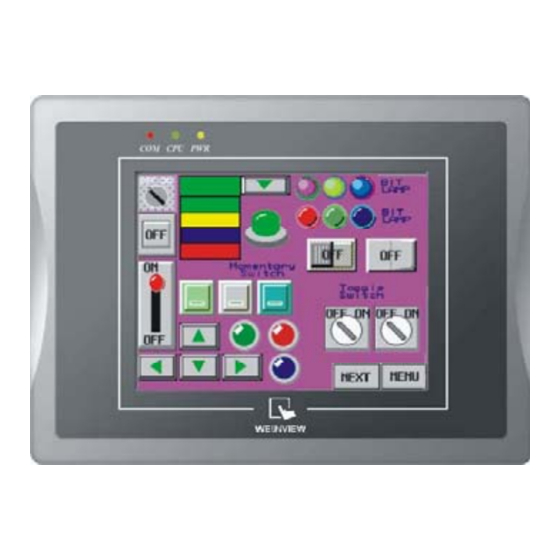
MMI-7xx Series
MMI-750T-HB, MMI-750T,
MMI-750, MMI-720
Installation Instruction
1
Advertisement
Table of Contents

Summary of Contents for KEP MMI-7 Series
-
Page 1: Table Of Contents
MMI-7xx Series MMI-750T-HB, MMI-750T, MMI-750, MMI-720 Installation Instruction MMI-7xx Series ............................1 1.0 Environmental Considerations ......................1 2.0 Mounting Instructions ......................... 1 3.0 Power Connections..........................2 4.0 Communications Connections......................6 5.0 Dip Switch Settings..........................9 6.0 MMI Indicator Lights.......................... 9 7.0 Other Hardware Considerations ...................... -
Page 2: Power Connections
2.2 Making a NEMA-4 Mounting The unit can be mounted into panels with a depth of 4”(105mm). It is recommended that Panel the unit be mounted on the front panel of a steel enclosure, through an appropriate Details opening*. Allow a clearance of 1”(25mm) around the sides of the unit for mounting hardware. - Page 3 Connecting high voltages or AC power mains to the DC input makes the unit Warning! unusable and may create a hazard to personnel. Such a failure could result in High Voltage serious personal injury, loss of life and or equipment damage. DC voltage sources should provide proper isolation from main AC power and similar hazards.
- Page 4 3.2 POWER CONNECTION +24 VDC Wiring Diagrams Connection Use 18 AWG wire to connect positive DC line to the +24V terminal and the DC ground to the 0V terminal. See text above about FG (Chassis Ground). Terminal Plug: To make a connection, strip about 3/8” of insulation off the end of the wire, turn the connector screw counterclockwise until the gap is wide open.
- Page 5 The MMI Series has been designed to operate satisfactorily in electromagnetic noise (immunity) and without emitting high levels of electrical noise into the environment (emission). The units are designed to meet European Community standards when installed per the wiring instructions in this manual. Compatibility Standards The MMI has been designed to meet electromagnetic compatibility for industrial environments.
-
Page 6: Communications Connections
The Auxiliary (AUX) RS485 port is also accessed through this connector. This port can be attached to a Computer via a special DB9 Female to DB9 Female Connection cable provided with the unit. (KEP P/N: MT5_PC) This port is activated automatically by the PC during: On line simulation, Port Activation Download and Upload activities. - Page 7 Different cables are required for various devices. See Controller Reference Section Cable for cable details. The KEP part numbers have the SMIC prefix. Refer to a KEP Requirements catalog or data sheet for a complete listing of MMI compatible devices.
- Page 8 Ethernet Connections Units equipped with the Ethernet port can be connected to Ethernet devices using standard 10T CAT5 Ethernet cables. Routing may pass through Hubs and Servers as needed to connect to the PLC. The Ethernet port can also be used for MMI Master/Slave communications using the same type of configurations.
-
Page 9: Dip Switch Settings
Case 3: Ethernet Connections: Units equipped with the Ethernet port can be connected via Ethernet to a Master and Slaves using standard 10T Ethernet cables. Slave to Master, connect the Ethernet ports with a standard (Category 5) Ethernet 10T crossover cable (RJ-45 to RJ45). Alternatively, use standard cables with routing passing through Hubs and Servers as needed. -
Page 10: Trouble Shooting
7.2 BATTERY REPLACEMENT The MMI-7xx takes one coin type of CR2032 lithium battery to backup the recipe data and keep the RTC running. Battery specification: CR2032 3V lithium battery. Steps for battery replacement: 1. Use EasyManager to backup the retentive memory data. 2. -
Page 11: Specifications
Use our toll free number to contact KEP if persistent problems are encountered. Telephone: 1-800-631-2165. If the product must be returned for any reason, be sure to call KEP and get a Return Goods Authorization (RGA) number first. Units should be returned in their original packaging container, otherwise, any suitable rigid container can be used as a substitute. - Page 12 Computer requirements include at least a Pentium 90Mhz PC, 16MB RAM, 10MB available hard disk space, minimum 800x600 resolution VGA, and one available RS-232 serial port. 9.4 DIMENSIONAL SPECIFICATION Front View Side View Bottom View Rear View Kessler Ellis Products 10 Industrial Way East Eatontown, NJ 07724 Phone: 732-935-1320 Fax: 732-935-9344 www.kep.com 990030REV09SEP05...

