Table of Contents
Advertisement
Quick Links
Advertisement
Table of Contents

Related Manuals for Titan TTS2


Summary of Contents for Titan TTS2
- Page 2 Preface Thank you for purchasing our total station! This manual is your good helper, please read it before operating the instrument and keep it properly. Product Validation In order to get our best service, please give the feedback about the version, number, purchasing date of the instrument and your valuable suggestions to us after you purchase our product.
- Page 3 Features Rich Features--our total station carries abundant surveying application, at the same time has the functions of data storage, parameter settings and etc. It’s suitable for all kinds of professional measurements. Absolute code disc Equipped with absolute code disc, the instrument can measure after switched on .Even if reset the battery halfway, the azimuth information will not be lost.
- Page 4 term. When transporting the instrument, you should store it in box and be careful to avoid extrusion, collision and violent vibration. A soft mat around the boxes is required for long-distance transport. When setting the instrument, it’s better to work with high-quality wooden tripod for stability and measurement accuracy.
- Page 5 Warnings: It’s dangerous to use Class 3R Laser instrument improperly. Precautions: In order to avoid causing damage, the proper precautions should be taken for you and control well the distance (in accordance with the standard “IEC60825-1:2001”) that may occur hazards. The following is the main part of the explanation of the IEC Standard Publication: Class 3R Laser Products are used in outdoors and on building...
-
Page 6: Table Of Contents
Content 1. Use of instrument............10 2. Names and functions of the components....11 2.1 Names of the components..........11 2.2 The information of the displays........13 2.3 Functional keys under the basic measurement mode...17 2.3.1 Angle mode (including three pages)....17 2.3.2 Distance measurement mode......18 2.3.3 Coordinate measurement mode......19 2.3.4 Explanation of saving data........ - Page 7 3.13 Selecting Data File............27 4. Preparations before measurements.......28 4.1 Unpacking and storing instruments......28 4.2 Set up the instrument............ 28 4.2.1 Using plummets to center and level (align)..28 4.2.2 Using centering device to center....... 29 4.3 Loading and unloading of battery........ 30 4.4 Reflecting Prism............
- Page 8 8.1 Offset (Angle)...............45 8.2 Offset (Dist1)..............46 8.3 Offset (Dist2)..............47 8.4 Offset (Plane)..............48 8.5 Offset (Column)............49 9. Menu................52 9.1 Surveying..............52 9.1.1 Operation............52 9.1.2 Preparation............53 9.1.3 Station and backsight.........53 9.1.3.1 Example for set station........54 9.1.3.2 Example for setting angle.......56 9.1.4Measurement............
- Page 9 9.4.1.1 “Input T.H” Mode.......... 79 9.4.1.2 “Without T.H”..........80 9.4.2 Resection............81 9.4.3 MLM..............81 9.4.4 Coord.Z..............82 9.4.5 Area measurement..........83 9.4.6 Projection............85 9.4.7 Roadway............86 9.5 Options................86 9.6 Adjust................88 9.6.1 Calibrate I.E............88 9.6.2 Calibrate TILT:X..........88 9.6.3 Calibrate TILT:Y..........90 9.7 Config (Instrument constant)........91 9.8 Select code file..............91 9.9 Gird scale..............
- Page 10 11.4 The Perpendicularity of Collimation axis and Cross axis (2C)..................103 11.5 Vertical plate index zero automatic compensation... 104 11.6 Vertical index error (angle i) and set vertical index 0 ....................104 11.7 Centering device............105 11.8 Addictive constant (K)..........106 11.9 The parallelism of collimation axis and photoelectricity axis..............107 11.10 Non-prism ranging..........107 12.
-
Page 11: Use Of Instrument
1. Use of instrument The total station is such an instrument that measures the azimuth and distances to destination and can calculate the destination point coordinates automatically. It plays an important role in the economic construction and national defense construction. General Survey, exploration and mining of minerals, the construction of railways, roads, bridges, irrigation, urban planning and construction is driven by electronic total station measurements. -
Page 12: Names And Functions Of The Components
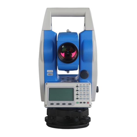
2. Names and functions of the components 2.1 Names of the components... -
Page 14: The Information Of The Displays
2.2 The information of the displays Symbols on the keyboard Keys Name Function In the basic interface,enter the angle Angle measurement . Under other modes, move measurement the cursor up or up to select the options. In the basic interface,enter the distance Distance mode DIST... - Page 15 The characters at the bottom line of the F1~F4 Soft Keys display indicate the meaning of the soft keys. Input numbers or characters or choose the Number keys menu In any measurement interface, you can enter the star key interface .You can set the Star key ★...
- Page 16 Slope distance. dSD is to stake out differences between slope distances. Northing. dN is to stake out differences between north-coordinates. Easting. dE is to stake out differences between East-coordinates. Elevation. dZ is to stake out differences between Z-coordinates EDM(Electronic Distance Measurement) is in progress. Unit in meters (metric units) Units in feet Units in American feet...
- Page 17 Info. Displays the name, code and coordinate of the current station and back-sight station. Settings Set the height of the instrument and the target Enter coordinates of the station where instrument is placed. Enter coordinates of the point where the target is. Meas Start rangefinders to measure distance Save...
-
Page 18: Functional Keys Under The Basic Measurement Mode
2.3 Functional keys under the basic measurement mode 2.3.1 Angle mode (including three pages) Page Soft key Reference Function Record the measured angle to the Save selected file. Set the horizontal angle as 0° 0set Set your desired horizontal angle by inputting ,but the angle should not be greater than 360°... -
Page 19: Distance Measurement Mode
Switch between HR (horizontal right/ clockwise) and HL (horizontal left/ anticlockwise) mode Vertical Angle Mode (altitude angle(Vh), Zenith(Vz) Display the first page of the soft key functions. The key [★] is used to set contrast, light, compensator and parameters of distance measurement . It can work under the basic modes. -
Page 20: Coordinate Measurement Mode
2.3.3 Coordinate measurement mode Page Soft key Reference Function Start coordinate measurement and record Save the measured data into the selected files (measurement file ‘File(.MEA)’ or coordinate file ‘File(.COO)’ are selected in surveying function). Start coordinate measurement Meas Switch between four distance Mode measurement mode [single accurate measurement (sngl)/ repeated accurate... -
Page 21: Explanation Of Saving Data
2.3.4 Explanation of saving data If you have never selected the measurement file and your first time to use the [Save] soft key, a dialogue box of ‘Select file’ would appear to the screen. Mention that this is a good chance for you to select all files that the instrument may use. - Page 22 pressure, and view the signal. (The setting of the distance measurement. After you input the temperature and pressure, pressing [F1] can automatically calculate the value of PPM, if you are not satisfied with the value, you can input and save it). The interface of picture as shown below:...
-
Page 23: Initial Setup
3. Initial setup 3.1 On & Off Press the power key until the screen displays pictures. The instrument is now switched on. After self-checking, the instrument enters Angle Mode automatically (see Angle Mode for details) Pressing power key will leads to a dialogue box. Press [ENT] to turn off the instrument. -
Page 24: Signal
appear as followed. 3.5 Signal The function of signal is to display the intensity of signal of EDM (Electrical Distance Measurement). It can help achieve ideal aiming result under poor conditions. If it is too difficult to be found, using signal can easily aim at the target. Continuing with the explained operation in 3.4, you may press [Signal] and the intensity of signal is displayed in the ‘Signal’... -
Page 25: Set Up The Atmospheric Correction Value (Ppm) Directly
The standard atmospheric value of our series Total Station (i.e. the atmospheric conditions when the correction is zero) Atm: 1013 Pa △S= 277.825- 0.29434P/(1+0.003661T) (ppm) Temp:20℃ The calculation of atmospheric correction △S: correction coefficient (unit: ppm) In the formula: P: atmospheric pressure (unit: hPa) T: temperature (unit:℃) 3.6.1 Set up the Atmospheric Correction value (ppm) directly You may measure the temperature and pressure to find out the... -
Page 26: The Correction Of The Atmospheric Refraction And The Earth Curvature
3.7 The Correction of the Atmospheric refraction and the Earth Curvature When measuring horizontal distance and elevation, our instrument corrects the atmospheric refraction and the earth curvature automatically. The formulas of two corrections about our instrument are as followed: Corrected Horizontal Distance : D=S×[cosα+sinα×S×cosα(K-2) / 2Re] Corrected Elevation : H=S×[sinα+cosα×S×cosα(1-K) / 2Re]... -
Page 27: Setup Of Automatic Shutdown
3.10 Setup of Automatic Shutdown Refer to the operation “Menu→5.Options→3.Other options→2. Auto shut off”. The interface as shown in picture below: You may choose ‘Never’ to cancel the auto shutdown. When choosing 5, 10, 20 minutes opts, the instrument will shut down automatically if there is no key pressed. -
Page 28: Selecting Data File
constant after strict measurement (e.g. in standardization site for baseline being measured by authenticated units). 3.13 Selecting Data File The instrument needs large data and creates large data when it is operated. This data needs to be storied in the system files of the instrument as a file form. -
Page 29: Preparations Before Measurements
4. Preparations before measurements 4.1 Unpacking and storing instruments Unpacking Lay down the box gently with the top side facing up. Open the lock and take out the instrument. Storage Cover the telescope cover. Make sure that the vertical clamping screw and the level bubble face upwards. -
Page 30: Using Centering Device To Center
Using the plate level to level the instrument precisely Loosen the horizontal locking screw and turn the instrument around until the plate level is perpendicular to a line shaped with screws A and B. Adjust the screws A and B to make the bubble in the center of the level; Turn the instrument approximately 90°... -
Page 31: Loading And Unloading Of Battery
center and that the top is leveled. Screw up the three locking screw; Make sure that the center of the tripod top is right above the station; Stamp one foot on the ground with your feet. Install the instrument gently on the top of the tripod and screw up the screw connection. -
Page 32: Reflecting Prism
temperature range. ▲A battery can be recharged for 300-500 times. ▲A monthly recharging is required if the instrument is not used for a long time. 4.4 Reflecting Prism. When measuring distance with prism mode, a reflecting prism must be set at the target site. You can connect the prism to the base, and then connect the base onto the tripod .you can also set the prism onto the centering rod. - Page 33 numbers. ● Input letters Example 1: Entering to the interface of selecting file in the surveying, which needs to input “SUN1A” in the edit box Press [Num.] to switch to the mode of inputting letters. Press [7], then, “S” displays in the edit box; Wait 0.4 seconds, then press [7] again, “SS”displays in the edit box;...
- Page 34 ● Input numbers Example 2: Take surying mode for example in the menu, Select file (.MEA&.COO) and press [Enter], Inputting the station and press [STA] and [F3],which needs to input “-123.456” in the edit box. Because the edit box “NO” can’t be letter, the inputting mode will default to “Alph.”, and can’t be switched to “Num.”.
-
Page 35: Notice For Using U Disk
The order of the keys:[1]→[2]→[3]→[·]→[4]→[5]→[5]→[6]; The result is as shown below: After completing the input, press [F4] to confirm the input or press [ESC] to cancel it. If it is over “360°”, a prompt box will appear “Overtop!”. 4.8 Notice for using U disk The machine supports up to 8G U disk read and write, when running the program, don’t insert or pull out the U disk. -
Page 36: Angle Mode
5. Angle mode The instrument would enter the Angle Mode automatically after switched on. You can also enter this Mode by pressing [ANG] under basic measurement mode. This Mode involves three pages switched by the key [F4]. Their functions are explained as followed: 5.1 Save Function: Save the current angle to selected measured file. -
Page 37: 0Set
5.2 0set Function: set the horizontal angle as 0 °00′00″. Press [F2](0set); ● Asking “Set 0?”, press [ENT] to set 0 or [ESC] to exit this ● operation. In order to make sure the accuracy, you may press [ENT] lightly. 5.3 Hset Function: Set the horizontal angle as wanted angle. -
Page 38: Angle By Repetition
5.5 Angle by repetition Function: Under right horizontal angle mode, you can measure angle repeatedly. Enter the interface of angleoby repetition ● Count: The times of the measurement; Ht: The sum of angle; Hm: The average value of angle Aim at point ‘A’, then press [F1] (0 set); ●... -
Page 39: Slope (V%)
Aim at point ‘A’ again by horizontal motion and tangent ● screw and press [F3](Rel.); Aim at point ‘B’ again by horizontal motion and tangent ● screw and press [F3](Hold); Repeat the steps above until the measurement times wanted; ● If want to exit this function ,just press [F2](Exit),then press ●... -
Page 40: Mode
right angle (HR) and left angle (HL). HR: Right angle mode .When the alidade is rotated clockwise, the horizon angle is increscent; HL: Left angle mode. When the alidade is rotated anticlockwise, the horizon angle is decreasing. 5.9 V mode Vz: Zenith Mode;... -
Page 41: Distance Mode
6. Distance mode Press [DIST] to enter the distance measurement mode, which has two interfaces . The functions of first interface are “Save”, “Meas.” and “Mode”; The functions of the second interface are “Offset”, “S.O” and “m/f/i”. The two interfaces shown as below: 6.1 Save After pressing [F1], whether recorsing after the completion ●... -
Page 42: Offset
Press [▲] or [▼] to move the “[]” the wanted option , then press [ENT] to save. 6.4 Offset Press [Offset] to enter the interface of offset (will described in the offset function). 6.5 Stake out (S.O) Enter the distance stakeout function The keys [F1]-[F3] is to select the stakeout mode. -
Page 43: Coordinate Mode
7. Coordinate mode Press [CORD] to enter the coordinate measurement mode. According to the diagram below, please set up the coordinates station, azimuth, target height and instrument height before coordinate measurement. There are three interfaces, which can be switched each other by pressing [F4].The functions of the first interface are “Save”, “Meas”, “Mode”;... - Page 44 select measured file, there will be a interface of “Select file (.MEA)” to let you select file.), which needs you the point name (Pt.N) ,Code and target height (T.H). The number of “Pt.N” defaults to added 1. The code is input according to your need, but the target height according to actual situation.
- Page 45 ‘STA’ (‘Station’) then set the BSS and orient. When orientation, please aim at the BS (target) precisely. Orientation can be done with [0set], [Hset] and [Hold] under Angle Mode. If the orientation is already done under Angle Mode, you don’t need to set BSS again under Coordinate Mode.
-
Page 46: Offset Mode
8. Offset mode includes five functions which “Offset(Angle)”, “Offset(Dist1)”,“Offset(Dist2)”,“Offset(Plane)”,“Offset(Column)”. These functions help for coordinate measurement, and can get the coordinates of the point which the prism can’t be at. Before operating these functions, please set ‘STA’, orientation, instrument height and target height. -
Page 47: Offset (Dist1)
Press [Meas] to start measurement. After measuring, press [Enter] to enter the interface of “Offset (angle)-Result”: Then, aim at offset point, you can get its coordinates. Pressing [Next P] to measure next point; press [Save] to save the coordinates of offset point; press [ESC] to exit. 8.2 Offset (Dist1) If have already known the front &behind and left &... -
Page 48: Offset (Dist2)
angle offset. After input the known distance, press [ENT] to enter the interface of “Offset (dist1)-Prism” : After measuring, press [Enter] to enter the result interface: Display the coordinates or offset point. Pressing [Next P] to measure next point; press [Save] to save the coordinates of offset point;... -
Page 49: Offset (Plane)
Input the distance, and press [Enter] to enter the interface of “Offset -Begin”. You must aim at point “P0” to measure.After measuring, press [ENT] to exit the interface to enter the interface of “Offset-End”. Aim at the end point, and press [ENT] after measuring. The coordinates of measured points are displayed, as shown in picture below: ◆If you need the coordinate of ‘A0’... -
Page 50: Offset (Column)
In the menu of “Offset”, select “4. Offset (Plane)” to enter the interface of “Offset –Pt.1”: Press [Meas] to measure point 1, and press [Enter] to receive the measured data and enter to the interface of “Offset (plane)-Pt.2”. Refer to the operation of measuring point 1 to get the data of point 2 and point 3 to enter the interface of “Offset (plane-Result)”;... - Page 51 distance, azimuth angle and coordinate of the cylinder by measuring the surface points of tangency P2 and P3. The average value of P2 and P3 is the azimuth angle of the cylinder. In the menu of “Offset”, select “5. Offset (Column)” to enter the interface of “Offset (Column) –Prism”: After measuring→...
- Page 52 After aim at the left edge, press [Enter] to enter the interface of “Offset (column)-L.edge”. After aim at the right edge, press [Enter] to enter the interface of “Offset (column)-Center”, as shown in picture below: Press [Next P] to enter the next offset, measurement. Press [Save] to exit.
-
Page 53: Menu
9. Menu In the basic measurement interface, press [MENU] to enter the menu interface, then, press [F4] to enter the next page. On the every page of menu, you can press number key to select. For example, if you press [1], the first option “1.Surveying” will be done. -
Page 54: Preparation
9.1.2 Preparation Firstly, you must select a file for surveying. When staring surveying, it appears a dialog for select file. Press [F2] (List) to enter the interface of “Select Disk”. If you have inserted the SDdisk, it would be displayed. After selecting a disk, press [ENT] to enter the interface of file list. -
Page 55: Example For Set Station
mode and coordinate measurement mode is common. You can input or change the station point or orientation angle. The two methods of setting station are as followed: 1) Set station by using the data in memory; 2) Input directly by keyboard; Three methods of the orientation angle of backsight point are followed: 1) Set backsight point by coordinate in memory;... - Page 56 5) The system checks the current coordinate file,if checks it ,then display the coordinates and you can press [F4] (Yes) to confirm the coordinates of station and exit to the interface of “Setup STA”; 6) Press [▼] to move the “->” to “Code” column; 7) Press [F1] to input code , then press [F4] to confirm it;...
-
Page 57: Example For Setting Angle
9) Press [F3] (Save) with the station coordinates displayed; 10) Press [F4](Yes) to finish setting station; 9.1.3.2 Example for setting angle The azimuth angle must be confirmed by measuring. You can save the data of orientation angle of backsight point by the following method. - Page 58 5) The system checks the current coordinate file, if checks it ,then display the coordinates and you can press [F4]; 6) Input “Code” and target height “T.H”; 7) Press [F3](Meas); 8) Aim at the backsight point, and select a key of measurement mode.
-
Page 59: 4Measurement
current settings will be saved in the measurement file; 9.1.4Measurement 1) In the first page of surveying, press [3] to enter the interface of “Meas”; 2) Press [F1](Input) to input the measurement point name ,then press [Enter] to input code; 3) Input target height (I.H) ,then press [Enter];... -
Page 60: Staking Out
6) After finishing measuring, press [F4](Yes) with data saved; 7) The point name will be added one, and you can measure next point. You can input name ,code and target height as the same way and measure as the same way of last point by pressing [F4](Ditto) or you can press [F3] to select the measurement methods;... -
Page 61: Staking Out Points
The Menu of staking out is as followed: The ‘Setup STA’ and ‘Setup BSS’ are the preparation work for staking out. If you have already setup them, re-setting them are not necessary. 9.2.1 Staking out points Two methods for staking out to be selected: 1) Retrieve the coordinates in the memory by point nane;... - Page 62 4) Input the target height; 5) After setting the stake-out point, you can start to stake out. HR:The calculated angle of tak-outpoint HD: the calculated distance from instrument to stake-out point; Aim at the prism center, then press [F1](Dist) (or [F2](Coord.)) 6) The rotation angle of the alidade will be calculated by the instrument;...
-
Page 63: Polar Coordinates
8) When the values of “dHR”, “dHD” and “dZ”(dN, dE, dZ) are zero, the staking out is completed; [Dist] [Coord.] 9) Press [F4] (Next P) to enter the next point stake-out. Then, the last stake-out point will be displayed. If the last point name is number, then the next point name will be added 1. -
Page 64: Resection
4) After measuring, the measured coordinates is displayed. You can press [F4](Yes) to save the measured value, and the point name will be added 1; [Yes] → 9.2.3 Resection Set up instrument on a new point, and measure at most 5 known points to calculate the coordinates of this new point, the measurement of resection is as following: ●Resection by distance measurement :... - Page 65 3) Press [F1](Input) to input point “1”(Here, you can retrieve points) and press [F4]; [Enter]→ 4) If the point doesn’t exist in this file, tips “None Pt.n”. You can press [F3](Coord.) to input coordinates, then press [F4] to confirm; [Enter]→ 5) Press [F4](Yes) to enter the interface of “Input T.H”.
- Page 66 6) Aim at the known point 1, press [F3](Angle) or [F4](Dist). Press [F4](Dist) for example; 7) Start measuring; 8) Enter the input interface of point 2 ; 9) According to step 5)~step 8), when using [Dist] to measure, the residual will be calculated. 10) Press [F1] to measure other known points, which are at most five points;...
-
Page 67: File Manager
11) Press points 3 according to the step 3~ step 5; 12) You can press [F4](Calc) to check the result of resection, and the standard deviations of the coordinates is displayed. Unit (mm); 13) Press [F4] (Coord.) to view the coordinates of the new points. -
Page 68: File Dialogbox
9.3.1 File Dialogbox The operations of “Create a new file”, “delete file”, “view file”, and so on are called file dialogbox. These operations involve the file list. Select “File Dialogbox” to enter the interface of “Select Disk”, as shown in picture below: After selecting the disk, press [Enter] to enter the interface of file type, as shown in picture below: You can select different file list, here, you can press [6] to view... - Page 69 Operations for files: 1) View the file information Press [Info.] to view the selected file,as shown in picture below. Press [ENT] or [Exit] back to the file list interface; 2) Search file Press [Search] to enter the interface of “Search”, as shown in picture below.
- Page 70 After selecting a file, press [DEL] to enter the interface of “Del”, as shown in picture below. Press [ENT] to delete file and press [Exit] to cancel to delete file and back to file list interface. 5) View file When viewing the file data, you can just view the measurement file, coordinate file and code file.
-
Page 71: Import
Pressing [▼] can display the information of the next piece data; ●Press [Search] to enter the condition input interface, and you can input the point name which you want and press [Enter] ,then the system searches the data from the first piece (all name matched). If searching it, the cursor will be at the point , or will tip and back to the first piece data. -
Page 72: Import From Usb
You can input the file name used to save the received data, such as “123”(.COO). If the file exists in the instrument, prompts “File Exist”. If selecting [List], you can select a file in FLASH disk. After selecting file, press [Enter] to enter the interface of importing; The only column that can be set is the Baud. - Page 73 Press [2] to enter the interface of “Import data” interface, as shown in picture below: As an example of importing coordinate data, press [1] yo enter the interface of “Select file”. The files in the directory of “PROJECT” in U disk will be read. Press [▲]or [▼] to select coordinate file edited, such as “SUA.TXT”, and press [F4] to enter the interface of “Select Cd.type”...
-
Page 74: Export
the data in the U disk will be saved in to the instrument until finishing importing. 9.3.3 Export Select [Fileman]→[3](Export), as shown in picture below: 9.3.3.1 Export to PC Select [1] to enter the interface of “Export data”, as shown in picture below: Taking an example for measured data, press [1] to enter the next interface, you need to input the measurement file you want to export... -
Page 75: Export To Usb
After selecting the format, enter the interface of exporting, as shown in the picture below: The operation of key functions, which are [Fast] ,[Slow] you can refer to the “import”. You may be careful that the export file must be measurement and coordinate, or can’t be exported. -
Page 76: Export With Mini Usb Port
interface of “Input new filename”, which defaults the selected file with with “.txt” extension; Here, input the file name for saving the exported data, which will be saved in the directory of “PROJECT” in the U disk. If there is a same name file in the Udisk , it will tip. - Page 77 guidance of professionals, if the operation is wrong, it may lead to the instrument can’t work properly! This function is for you to upgrade the software of the instrument. Press [1] on the second page of “Fileman” to enter the interface of updating, as shown in picture below: 1) Input “PIN”...
- Page 78 4) Press key ‘1’ on the keyboard. The instrument enters the waiting state for sending programs. After the state, click‘Send File’ on the computer; 5) Select the new version of total station software and click ‘ Send ’ on the computer; 6) Then the computer displays the process of sending.
-
Page 79: Program
can press [5] to update boot image and press [6] to update language; 7) After update program, boot image, language, press [3] to end the update and press power button to turn on the instrument to run the updated program. 9.4 Program The operation in the menu of staking out : Press the key of [MENU] ,the instrument will enter into the... -
Page 80: Input T.h" Mode
There are two modes for ‘REM’ measurement: ‘Input TH’ and ‘without TH’. You can select ‘Input TH’ mode when you need the altitude from ground to target, otherwise ‘without TH’ when you need the altitude from any reference point to target. 9.4.1.1 “Input T.H”... -
Page 81: Without T.h
[ESC]:to quit REM measurement. You can choice according to the actual usage. 9.4.1.2 “Without T.H” After select this mode, enter the interface of “REM-Prism”: Aim at the prism, then press [Meas] to measure the horizontal distance from prism to prism and enter the interface of “REM-Base”; Aim at the reference point and press [Select] to enter the dialog of ‘REM-Altitude’... -
Page 82: Resection
9.4.2 Resection For the following steps, see reference in chapter 9.2.3 Resection. 9.4.3 MLM Diagram of “MLM” Measure the horizontal distance (dHD), slope distance (dSD), elevation difference (dVD) and azimuth angle (dHD) between two target. You may also input the coordinate or retrieve coordinate from files to calculate the value. -
Page 83: Coord.z
3) Get the coordinates by the same way of the “Step-1”, then press [ENT] to enter the interface of “MLM (A-B,A-C)-Result”; The result displayed is the measurement from first point to second point; If you press [Next P], you will repeat the operations of “MLM (A-B,A-C)-Step2”and “MLM (A-B, A-C)-Result”,and can get the measurement result of first point and other point;... -
Page 84: Area Measurement
point. Press [ENT] to end inputting and enter the measurement interface of “Coord.Z-No.1”; 3) Press [Meas] to start measuring. After measuring, the measured value will be displayed, and you can press [Enter] confirm this measurement, then keys [Next] ,[Mode]and [Calc] appears. You can press [Next] to continue the measurement , or [Calc] to enter the interface of “Coord.Z-Result”;... - Page 85 3) After pressing [Enter] , the point will be listed in the area measurement list , as shown in picture below: 4) The same way above, input the other points, which will be listed to area measurement list; The maximum of points is 20.(The coordinates in the list may be displayed incomplete because of the screen).
-
Page 86: Projection
9.4.6 Projection Diagram of “Projection” This function is used to measure the length (X) of the prism point deviation from the starting point of baseline, distance(Y) of the prism point deviation from baseline, and altitude difference (Z) of the prism point deviation from the starting point of baseline. The preparation before measurement: setting up the instrument height, the target height and defining the baseline. -
Page 87: Roadway
Press [Meas] to start measuring, then press [Enter] to enter the interface of “Project(End)”; Press [Meas] to start measuring, then you can press [Enter] to return to “project” menu and press [3](Project)(3.Project) to start projection measurement. Projection In the project menu, press [3](project) to enter the interface of “Project-Survey”;... - Page 88 Press [1] to enter the interface of “options” Press [2] to enter the interface of “Mode options”: Press [3], enter the interface of “Other options”: Taking “EDM” for example, the interface as shown below: Press [▲ ] or [ ▼] to move the “>” to the options needed, then press [Enter] to receive the select , and save it to system file.
-
Page 89: Adjust
9.6 Adjust Warning: The following functions must be carried out under the guidance of professionals, if the operation is wrong, it may lead to the instrument can’t work properly! Press [MENU]→[F4] →[1](Adjust) to enter the interface of “Adjust”: 9.6.1 Calibrate I.E To adjust index error, the system will first ask you to ‘Aim at a target F1’(face left). - Page 90 Enter the interface of tilt calibration: Specific steps are as follows: 1) After leveling the instrument, aim at the target F1 in the collimator face left, record the current vertical angle as V0. 2) Set the vertical angle to ‘V0+3′’with the help of the vertical tangent screw.
-
Page 91: Calibrate Tilt:y
to re-calibrate; In the correction process by pressing the ESC key, will exit, holding compensator parameters unchanged. 9.6.3 Calibrate TILT:Y Enter the interface of tilt calibration: 1) After leveling the instrument, aim at the target F1 in the collimator face left, record the current vertical angle as V0. 2) Set the vertical angle to ‘V0+3′’with the help of the vertical tangent screw. -
Page 92: Config (Instrument Constant)
to re-calibrate; In the correction process by pressing the ESC key, will exit, holding compensator parameters unchanged. 9.7 Config (Instrument constant) Operations are permitted only when the instrument was tested strictly. We recommend you to set it after it is tested by the factory or professional verification institutions. -
Page 93: Communication
Grid scale factor of coordinate=Altitude factor × Scale factor Distance calculation: 1) Grid scale distance(HDg)= HD×Grid scale factor HD= distance on the ground 2) Distance on the ground(HD)= HDg/Grid scale factor After input altitude, you can press [Enter] to calculate the “Scale”,as shown in the picture above. -
Page 94: Roadway
10. Roadway Roadway function is divided into two parts: Design Roadway and Stake out Roadway. You may stake out designed points according to the stake and deviation of the Designed Roadway. Select “[Menu]→4.Program→[F4](P2)→Select file (.MEA&.COO) and press [Enter]→1.Roadway” to enter the interface of road menu: If you have already imported [.LS] files into the instrument from the external, you may open the [.LS] file through ‘1.Open Shape file’. - Page 95 interface of “Define(H)-Begin”, then you can select the other lie type to input. After finishing the input, press [ENT] to enter the interface of “List of H curve”; Note: Do not define the length as ‘0’, which indicates ending the alignment.
-
Page 96: Intersection Method
The “R”(Radius) indicates the radius of end point of spiral transition curve; After inputting the “Line”, “Circle”, “Spiral”, press [ENT] to receive the input and exit to “Define(H)”. if you want to view the input, press [ENT] to finishing inputting and enter the interface of “List of H curve”;... -
Page 97: Vertical Alignment
‘PT’ is the intersection point of road. The “x” of “Px” is the number of intersection point. When inputting R,A1, and A2, they can’t be negative. If inputting the radius, the system will insert an arc with defined radius in between the former point and the next point. If inputting parameters A1 and A2 of the spiral, the system will insert defined spiral between the line and the arc. -
Page 98: Stake Out (Road)
In the “Roadway” menu, select “Re-define (V)” to enter the interface of “Define (V)-Begin”: After inputting the “Mark”, “Height” and “Len.” (Length), press [Enter] to confirm, and enter the interface of the point 01 input, as hown in picture below: Then, you can input the “Mark”, “Height”... -
Page 99: Selecting Roadway File
time for the demand so that staking out roadway with any mileage can be done easily. You may not be worried about the problem that the capacity of 20 point of horizontal alignment and 20 point of vertical alignment, because you can divide any long road into several pieces and save them into several line type files. -
Page 100: Setting Station And Bss(Backsight Point)
10.2.2 Setting station and BSS(backsight point) See reference in setup BSS and setup station 10.2.3 Stake out road Before staking out Roadway, please first enter the parameters required for staking out. e.g starting mileage, space between, “L dist”(left distance), “R dist”(right distance), “L dV” and “R dV”. After inputting, press [ENT] to enter ‘Roadway- Center’... - Page 101 The “Pt.n” indicates the mileage of the mark selected (which system accepts the maximum of is 8 characters).then you can press [Save] to save the information of staking out to the current coordinate file. Press [Enter] to enter the interface of “Roadway-Calc”, which displays the azimuth angle and horizontal distance: You can select F1[Dist] to stake out by polar coordinate or F3[Coord.] to stake out by coordinate, which refer to “9.2.2 Polar...
-
Page 102: Adjustments And Corrections
11. Adjustments and Corrections The instrument is under strict test and calibration, the quality is accord with the standard demand. But after a long-distance transportation and environment change, the small change of instrument parameter is inevitable. Therefore, the new purchased instruments should be checked and calibrated before surveying to ensure the precision. -
Page 103: Reticle Of The Telescope
11.3 Reticle of the telescope Check 1. Aim at a target A from the telescope after leveling the instrument the cross wire on the reticle. Lock the instrument with vertical and horizontal locking knob after aiming at A. 2. Rotate the vertical slow motion knob, move A point to the edge of the field of view (A 'points);... -
Page 104: The Perpendicularity Of Collimation Axis And Cross Axis (2C)
11.4 The Perpendicularity of Collimation axis and Cross axis (2C) Check 1. Set a target A in about 100m away, and make sure the vertical angle of the target is within ±3°.Precisely level the instrument and switch on it; 2. Make the telescope focused on target A in face left, and read the horizontal angle e.g. -
Page 105: Vertical Plate Index Zero Automatic Compensation
11.5 Vertical plate index zero automatic compensation Checkout 1. After Setting up and leveling the instrument, make the direction of the telescope consistent with the line between the center of the instrument and any of the foot screw; 2. The vertical plate index change to zero after switching on Tighten the vertical brake hand-wheel and the instrument display the current telescope vertical Angle;... -
Page 106: Centering Device
4. If | i |≥10", may be you need reset the zero value of vertical index; 5. For the following steps, see reference in chapter 11.6.1. Note: Repeat the checkout steps to retest the index error again (i Angle). If the index error still cannot accordance with requirements , it should check the three steps of calibration index zero setting (in the course of zero setting ,the vertical angle showed is not compensated and corrected, it is just for reference) to see whether it is incorrect,... -
Page 107: Addictive Constant (K)
5. Repeat step 4, check and calibrate until it meet the requirements; 6. With the laser plummet, unbolt the laser cover, using 1 # hex wrench to adjust the three screws, fasten one side and loosen the other side, and adjust the laser flare to point O; 7. -
Page 108: The Parallelism Of Collimation Axis And Photoelectricity Axis
method above, and the original instrument constant is ‘-20’, so the new value should be set as ‘-20-(5) =-15’; Input ‘-15’ through "menu-> 6->2" and then confirm. Use the vertical line of the reticle to orientate, make A, B and C at the same line accurately. - Page 109 it 5 meters and 20 meters away. Start laser direction function. Focus on the reflector center by the telescope crosshair center, then check the position of the red laser point. Generally speaking, the telescope is equipped with special filter, human eyes can′t see laser point through the telescope, you can see the offset between the red laser point and the reflector crosshair center, you can observe this above the telescope or at the side face of reflector.
-
Page 110: Technical Parameters
12. Technical parameters Function Unit Configuration Imaging — Erect Magnification × Telescope Field of view — 1 ゜ 20′ Min.target distance Effective aperture 40/50(EDM) 2C index error (″) Angle i index error (″) Angle measurement Angle measurement — Absolute encoder (Hz, V) method Minimum reading... - Page 111 and white screen) Illumination — Support Wavelength 635nm Laser (optional) Laser Maximum output power Laser Plumb — Plumb (adjustable): not less than 0.4 m W, not more than 1.0 mW (″)/2 Tubular level Level ( ′ ) /2 Round level Built-in application —...
-
Page 112: Appendix A File Format Introduction (Sunway)
Appendix A File format introduction (Sunway) These following examples to instruct exported file format ST001,1.205,AD 100.000,100.000,10.000 BS001,45.2526,50.0000 BS001,1.800 98.2354,90.2314,10.235 A1,1.800,CODE1 104.662,99.567,10.214 A2,1.800,CODE1 78.3628,92.4612,4.751 A3,1.800,CODE1 63.2349,89.2547 NOTE this note Every record consists of two lines: The information of first line: record type, name, elevation, code Such as: STA refers to station point BKB refers to back sight Angle data... -
Page 113: Appendix B Bi-Directional Communication
Appendix B Bi-directional communication The total station controlled by external computer can sent the information about angle and distance. The settings of communication and protocol as follow: ● Baud rate: 2400~115200 available ● Data length: 8 ●Stop bits: 0 ●Parity bits: none ●protocol: ●Code: STX(02),CR(13),X_ON(17),X_OFF(19) The angle ans diatance data are transferred by a form of fixed...