Juniper SRX210 Series Manual
Services gateway
Hide thumbs
Also See for SRX210 Series:
- Hardware manual (204 pages) ,
- Manual (200 pages) ,
- Quick start manual (6 pages)

Related Manuals for Juniper SRX210 Series


Summary of Contents for Juniper SRX210 Series
- Page 1 SRX210 Services Gateway Hardware Published: 2012-03-01 Copyright © 2012, Juniper Networks, Inc.
- Page 2 Products made or sold by Juniper Networks or components thereof might be covered by one or more of the following patents that are owned by or licensed to Juniper Networks: U.S. Patent Nos. 5,473,599, 5,905,725, 5,909,440, 6,192,051, 6,333,650, 6,359,479, 6,406,312, 6,429,706, 6,459,579, 6,493,347, 6,538,518, 6,538,899, 6,552,918, 6,567,902, 6,578,186, and 6,590,785.
-
Page 3: Table Of Contents
PoE Classes and Power Ratings ........26 Configuring PoE Functionality on the SRX210 Services Gateway ....27 Copyright © 2012, Juniper Networks, Inc. - Page 4 Product Disposal Warning ........60 Copyright © 2012, Juniper Networks, Inc.
- Page 5 Gateway ............106 Copyright © 2012, Juniper Networks, Inc.
- Page 6 Monitoring the SRX210 Services Gateway Using Chassis Alarm Conditions ..149 Monitoring the SRX210 Services Gateway Power System ....152 Copyright © 2012, Juniper Networks, Inc.
- Page 7 Juniper Networks Technical Assistance Center ..... . . 155 Juniper Networks Technical Assistance Center ......155 Chapter 23 Returning the Services Gateway .
- Page 8 SRX210 Services Gateway Hardware viii Copyright © 2012, Juniper Networks, Inc.
- Page 9 Gateway in a Rack ..........98 Copyright © 2012, Juniper Networks, Inc.
- Page 10 Returning the Services Gateway ........157 Figure 28: Location of SRX210 Serial Number and Agency Labels ... . 159 Copyright © 2012, Juniper Networks, Inc.
- Page 11 3G Wireless Functionality ......... . 29 Table 13: Juniper Networks Wireless Modems Supported by the SRX210 Services Gateway .
- Page 12 Maintaining the Hardware ......... 141 Copyright © 2012, Juniper Networks, Inc.
- Page 13 Returning the Services Gateway ........157 Table 47: Return Procedure for SRX210 Services Gateway ....157 Copyright © 2012, Juniper Networks, Inc. xiii...
- Page 14 SRX210 Services Gateway Hardware Copyright © 2012, Juniper Networks, Inc.
-
Page 15: About The Documentation
® To obtain the most current version of all Juniper Networks technical documentation, see the product documentation page on the Juniper Networks website at http://www.juniper.net/techpubs/ If the information in the latest release notes differs from the information in the documentation, follow the product Release Notes. -
Page 16: Table 1: Notice Icons
The console port is labeled CONSOLE on routing platform components. < > (angle brackets) Enclose optional keywords or variables. < > stub default-metric metric Copyright © 2012, Juniper Networks, Inc. -
Page 17: Documentation Feedback
Software release version (if applicable) Requesting Technical Support Technical product support is available through the Juniper Networks Technical Assistance Center (JTAC). If you are a customer with an active J-Care or JNASC support contract, Copyright © 2012, Juniper Networks, Inc. -
Page 18: Self-Help Online Tools And Resources
7 days a week, 365 days a year. Self-Help Online Tools and Resources For quick and easy problem resolution, Juniper Networks has designed an online self-service portal called the Customer Support Center (CSC) that provides you with the following features: Find CSC offerings: http://www.juniper.net/customers/support/... -
Page 19: Overview
PART 1 Overview Introduction on page 3 Hardware Components and Specifications on page 7 Mini-Physical Interface Modules on page 23 Power over Ethernet on page 25 3G Wireless Functionality on page 29 Copyright © 2012, Juniper Networks, Inc. - Page 20 SRX210 Services Gateway Hardware Copyright © 2012, Juniper Networks, Inc.
-
Page 21: Introduction
Accessing the SRX210 Services Gateway on page 4 About the SRX210 Services Gateway The Juniper Networks SRX210 Services Gateway offers complete functionality and flexibility for delivering secure and reliable data, along with multiple interfaces that support WAN and LAN connectivity and Power over Ethernet (PoE). -
Page 22: Accessing The Srx210 Services Gateway
The J-Web interface provides access to all Junos functionality and features. Junos OS command-line interface (CLI): Juniper Networks command shell that runs on top of a UNIX-based operating system kernel. The CLI is a straightforward command interface. On a single line, you type commands that are executed when you press the Enter key. - Page 23 Junos OS Initial Configuration Guide for Security Devices Junos OS Monitoring and Troubleshooting Guide for Security Devices Related SRX210 Services Gateway Description on page 3 Documentation SRX210 Services Gateway Specifications on page 7 Copyright © 2012, Juniper Networks, Inc.
- Page 24 SRX210 Services Gateway Hardware Copyright © 2012, Juniper Networks, Inc.
-
Page 25: Hardware Components And Specifications
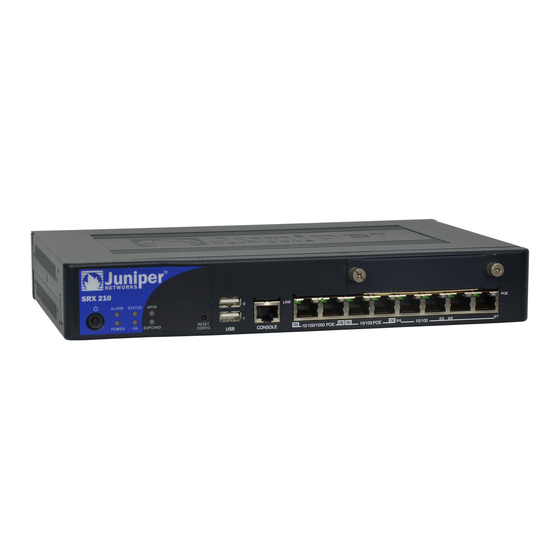
Figure 1 on page 7 shows the SRX210 Services Gateway chassis (for low memory, high memory, and PoE models). Figure 1: SRX210 Services Gateway Table 5 on page 8 provides information on the physical specifications of the device. Copyright © 2012, Juniper Networks, Inc. -
Page 26: Table 5: Srx210 Services Gateway Specifications
(ESD) strap to an ESD point and place the other end of the strap around your bare wrist. Failure to use an ESD strap could result in damage to the services gateway. Copyright © 2012, Juniper Networks, Inc. -
Page 27: Srx210 Services Gateway Front Panel And Back Panel Views (Low Memory, High Memory, And Poe Versions)
Table 6 on page Table 6: SRX210 Services Gateway Front Panel Components Number Component Mini-PIM slot Power button LEDs: Status, Alarm, Power, 3G ExpressCard, Mini-PIM, HA Reset Config button Copyright © 2012, Juniper Networks, Inc. -
Page 28: Srx210 Services Gateway Back Panel
Figure 3 on page 10 correspond to the numbers in Table 7 on page Table 7: SRX210 Services Gateway Back Panel Components Number Component Power supply point Cable tie holder Grounding point Lock ExpressCard slot Copyright © 2012, Juniper Networks, Inc. -
Page 29: Srx210 Services Gateway Leds
Figure 4 on page 11 shows the SRX210 Services Gateway front panel LEDs. Table 8 on page 12 lists the LED indicators on the SRX210 Services Gateway front panel. Figure 4: SRX210 Services Gateway Front Panel LEDs Copyright © 2012, Juniper Networks, Inc. -
Page 30: Table 8: Srx210 Services Gateway Front Panel Components Leds
Red and steadily on indicates that the HA links are not working as expected. Amber and steadily on indicates that some HA links are not working as expected. Off indicates that HA is not enabled. Copyright © 2012, Juniper Networks, Inc. -
Page 31: Ethernet Port Leds
SRX210 Services Gateway Ethernet port LEDs. Figure 5: SRX210 Services Gateway Ethernet Port LEDs NOTE: The numbers in Figure 5 on page 13 correspond to the numbers in Table 9 on page Copyright © 2012, Juniper Networks, Inc. -
Page 32: Srx210 Services Gateway Built-In Interfaces
SRX210 Services Gateway Cooling System on page 18 SRX210 Services Gateway Power Supply on page 19 SRX210 Services Gateway Built-In Interfaces Table 10 on page 15 summarizes the interface ports supported on the SRX210 Services Gateway. Copyright © 2012, Juniper Networks, Inc. -
Page 33: Table 10: Srx210 Services Gateway Built-In Hardware Interfaces
Power over Ethernet on the SRX210 To connect power devices Services Gateway (PoE to receive network version). connectivity and electric power (PoE functionality) (For the PoE model of the SRX210 Services Gateway) Copyright © 2012, Juniper Networks, Inc. - Page 34 LAN and WAN functionality along with connectivity to various media types. For more information about the supported Mini-PIMs, see the SRX Series Services Gateways for the Branch Physical Interface Modules Hardware Guide. Copyright © 2012, Juniper Networks, Inc.
-
Page 35: Srx210 Services Gateway Boot Devices And Dual-Root Partitioning Scheme
We strongly recommend that only transceivers provided by Juniper Networks be used on an SRX210 Services Gateway. We cannot guarantee that the interface module will operate correctly if third-party transceivers are used. Contact Juniper Networks for the correct transceiver part number for your device. Related... -
Page 36: Srx210 Services Gateway Cooling System
The airflow produced by the fans keeps device components within the acceptable temperature range. Figure 6 on page 19 shows the airflow through the chassis for the SRX210 Services Gateway with Low Memory, High Memory, and PoE models. Copyright © 2012, Juniper Networks, Inc. -
Page 37: Srx210 Services Gateway Power Supply
SRX210 Services Gateway Power Supply The power supply for the SRX210 Services Gateway is external. You must use the power supply adapter provided by Juniper Networks to provide power to the services gateway. Figure 7 on page 20 shows the label for the 12 V power supply. -
Page 38: Figure 7: Srx210 Services Gateway - 12 V Power Supply
Figure 8 on page 20 shows the label for the 48 V power supply. Figure 8: SRX210 Services Gateway — 48 V Power Supply Figure 9 on page 21 shows the label for the 54 V power supply. Copyright © 2012, Juniper Networks, Inc. -
Page 39: Figure 9: Srx210 Services Gateway - 54 V Power Supply
Memory, and PoE Versions) on page 9 SRX210 Services Gateway Boot Devices and Dual-Root Partitioning Scheme on page 17 SRX210 Services Gateway Cooling System on page 18 Monitoring the SRX210 Services Gateway Power System on page 152 Copyright © 2012, Juniper Networks, Inc. - Page 40 SRX210 Services Gateway Hardware Copyright © 2012, Juniper Networks, Inc.
-
Page 41: Mini-Physical Interface Modules
SRX210 Services Gateway Description on page 3 Documentation SRX210 Services Gateway Specifications on page 7 SRX210 Services Gateway Hardware Features on page 4 SRX210 Services Gateway Built-In Interfaces on page 14 Physical Interface Modules Copyright © 2012, Juniper Networks, Inc. - Page 42 SRX210 Services Gateway Hardware Copyright © 2012, Juniper Networks, Inc.
-
Page 43: Power Over Ethernet
Table 11 on page 25 lists the SRX210 Services Gateway PoE specifications. Table 11: SRX210 Services Gateway PoE Specifications Power Management Schemes Values Supported standards IEEE 802.3 AF (PoE) IEEE802.3 AT (PoE+) Legacy (pre-standards) Copyright © 2012, Juniper Networks, Inc. -
Page 44: Poe Classes And Power Ratings
The PoE+ functionality is available from Junos OS Release 10.2 or later. The PoE+ functionality is available only if your gateway is using 54V power supply. You can order the 54V power supply from Juniper Networks. Contact your Juniper Networks customer service representative for more information. -
Page 45: Configuring Poe Functionality On The Srx210 Services Gateway
SRX210 Services Gateway Front Panel and Back Panel Views (Low Memory, High Memory, and PoE Versions) on page 9 SRX210 Services Gateway Built-In Interfaces on page 14 SRX210 Services Gateway LEDs on page 11 SRX210 Services Gateway Mini-Physical Interface Modules on page 23 Copyright © 2012, Juniper Networks, Inc. - Page 46 SRX210 Services Gateway Hardware Copyright © 2012, Juniper Networks, Inc.
-
Page 47: 3G Wireless Functionality
(Low Memory, High Memory, and PoE Versions)” on page Supported Modem Types Table 13 on page 29 lists the modem types supported on the SRX210 Services Gateway. Table 13: Juniper Networks Wireless Modems Supported by the SRX210 Services Gateway Wireless Cards Release Supported EXPCD-3G-CDMA-V: 3G EVDO ExpressCard for Verizon Junos OS Releases 9.6, 10.0,... -
Page 48: Using The 3G Expresscard
SRX210 Services Gateway Hardware Table 13: Juniper Networks Wireless Modems Supported by the SRX210 Services Gateway (continued) Wireless Cards Release Supported EXPCD-3G-CDMA-S: 3G EVDO ExpressCard for Sprint. Currently Junos OS Releases 9.6, 10.0, available from Juniper Networks. 10.1, and 10.2 Sierra Wireless AirCard 880E/881E supporting Global System Junos OS Releases 9.5 and 9.6... -
Page 49: Physical Specifications
Type Standard ExpressCard with 34 modules ExpressCard width 1.33 in. (34 mm) Thickness 0.19 in. (5 mm) Connector pins Max power consumption 1.3 watts Voltage supply 3.3 V (primary source) 1.5 V (secondary source) Copyright © 2012, Juniper Networks, Inc. -
Page 50: Installing The 3G Expresscard In The Srx210 Services Gateway Expresscard
Installing the 3G ExpressCard in the SRX210 Services Gateway ExpressCard Slot TIP: Placing the SRX210 Services Gateway on a flat, level surface, with the Juniper Networks logo facing up, will make it easier to align and insert the 3G ExpressCard in the ExpressCard slot. CAUTION: 3G ExpressCard is not hot-swappable on the SRX210 Services Gateway. -
Page 51: Srx210 Services Gateway 3G Expresscard Basic Cli Commands
OTASP — Activates over the air service provisioning. request modem wireless activate otasp cl-0/0/8 dial-string calling number Unlocks the GSM SIM. request modem wireless gsm sim-unlock cl-0/0/8 Unlocks the SIM automatically on reboot set interfaces cl-0/0/ 8 cellular-options gsm-options sim-unlock-code Copyright © 2012, Juniper Networks, Inc. - Page 52 For more information about configuring the 3G wireless interface, see Junos OS Interfaces and Routing Configuration Guide. Related SRX210 Services Gateway 3G ExpressCard Overview on page 29 Documentation Installing the 3G ExpressCard in the SRX210 Services Gateway ExpressCard Slot on page 32 Copyright © 2012, Juniper Networks, Inc.
-
Page 53: Planning
PART 2 Planning Site Preparation on page 37 Safety and Regulatory Compliance Information on page 45 Power Guidelines, Requirements, and Specifications on page 67 Interface Cable Specifications and Connector Pinouts on page 71 Copyright © 2012, Juniper Networks, Inc. - Page 54 SRX210 Services Gateway Hardware Copyright © 2012, Juniper Networks, Inc.
-
Page 55: Site Preparation
Electrical Wiring Guidelines” on page 67 Locate sites for connection of system grounding. “SRX210 Services Gateway Power Calculate the power consumption and Specifications and Requirements” requirements. on page 68 Rack Installation Copyright © 2012, Juniper Networks, Inc. - Page 56 Installation Overview for the SRX210 Services Gateway on page 77 SRX210 Services Gateway Cabinet Requirements on page 39 SRX210 Services Gateway Rack Requirements on page 40 Clearance Requirements for Airflow and Hardware Maintenance of the SRX210 Services Gateway on page 41 Copyright © 2012, Juniper Networks, Inc.
-
Page 57: General Site Guidelines For Installing The Srx210 Services Gateway
19 in. (48.3 cm) as defined in Cabinets, Racks, Panels, and Associated Equipment (document number EIA-310–D) published by the Electronics Industry Association ( http://www.eia.org You can mount the services gateway horizontally in the cabinet. Copyright © 2012, Juniper Networks, Inc. -
Page 58: Srx210 Services Gateway Rack Requirements
The services gateway cannot be center mounted in a rack. Table 18 on page 41 provides the details of requirements for rack size, clearance, airflow, spacing of mounting brackets and flange holes, and connecting to the building structure. Copyright © 2012, Juniper Networks, Inc. -
Page 59: Clearance Requirements For Airflow And Hardware Maintenance Of The Srx210 Services Gateway
For service personnel to remove and install hardware components, there must be adequate space at the front and back of the device. Allow at least 24 in. (61 cm) both in front of and behind the device. Copyright © 2012, Juniper Networks, Inc. -
Page 60: Srx210 Services Gateway Electrical And Power Requirements
There are factors you must consider while planning the electrical wiring and power availability at your site. These factors include the following requirements: Power specifications and requirements for the device Electrical wiring guidelines for the device installation site Copyright © 2012, Juniper Networks, Inc. - Page 61 Grounding guidelines and specifications for the device Related SRX210 Services Gateway Site Electrical Wiring Guidelines on page 67 Documentation SRX210 Services Gateway Power Specifications and Requirements on page 68 Site Preparation Checklist for the SRX210 Services Gateway on page 37 Copyright © 2012, Juniper Networks, Inc.
- Page 62 SRX210 Services Gateway Hardware Copyright © 2012, Juniper Networks, Inc.
-
Page 63: Safety And Regulatory Compliance Information
Requirements on page 65 SRX210 Services Gateway Compliance Statements for Acoustic Noise on page 65 SRX210 Services Gateway Definition of Safety Warning Levels This topic defines the following four levels of safety warnings used in Juniper Networks technical publications: NOTE: You might find this information helpful in a particular situation or might otherwise overlook it. - Page 64 Aviso Este símbolo de aviso indica perigo. Encontra-se numa situação que lhe poderá causar danos físicos. Antes de começar a trabalhar com qualquer equipamento, familiarize-se com os perigos relacionados com circuitos eléctricos, e com quaisquer práticas comuns que possam prevenir possíveis acidentes. Copyright © 2012, Juniper Networks, Inc.
-
Page 65: Srx210 Services Gateway General Safety Guidelines And Warnings
Wear safety glasses if you are working under any conditions that could be hazardous to your eyes. Do not perform any actions that create a potential hazard to people or make the equipment unsafe. Copyright © 2012, Juniper Networks, Inc. -
Page 66: Qualified Personnel Warning
¡Atención! Estos equipos deben ser instalados y reemplazados exclusivamente por personal técnico adecuadamente preparado y capacitado. Varning! Denna utrustning ska endast installeras och bytas ut av utbildad och kvalificerad personal. Copyright © 2012, Juniper Networks, Inc. -
Page 67: Restricted Access Area Warning
Uma área de acesso restrito é uma área à qual apenas tem acesso o pessoal de serviço autorizado, que possua uma ferramenta, chave e fechadura especial, ou qualquer outra forma de segurança. Esta área é controlada pela autoridade responsável pelo local. Copyright © 2012, Juniper Networks, Inc. -
Page 68: Preventing Electrostatic Discharge Damage To The Services Gateway
When removing or installing a component, always place it component-side up on an antistatic surface, in an antistatic card rack, or in an electrostatic bag. If you are returning a component, place it into an electrostatic bag before packing it. See Figure 11 on page Copyright © 2012, Juniper Networks, Inc. -
Page 69: Srx210 Services Gateway Fire Safety Requirements
In addition, establish procedures to protect your equipment in the event of a fire emergency. Juniper Networks products should be installed in an environment suitable for electronic equipment. We recommend that fire suppression equipment be available... -
Page 70: Srx210 Services Gateway Safety Requirements, Warnings, And Guidelines
To keep warranties effective, do not use a dry chemical fire extinguisher to control a fire at or near a Juniper Networks services gateway. If a dry chemical fire extinguisher is used, the unit is no longer eligible for coverage under a service agreement. -
Page 71: Laser And Led Safety Guidelines And Warnings
¡Atención! Producto láser Clase I. Varning! Laserprodukt av klass 1. Class 1 LED Product Warning WARNING: Class 1 LED product. Waarschuwing Klasse 1 LED-product. Varoitus Luokan 1 valodiodituote. Attention Alarme de produit LED Class I. Copyright © 2012, Juniper Networks, Inc. -
Page 72: Laser Beam Warning
Radiation from Open Port Apertures Warning WARNING: Because invisible radiation may be emitted from the aperture of the port when no fiber cable is connected, avoid exposure to radiation and do not stare into open apertures. Copyright © 2012, Juniper Networks, Inc. -
Page 73: Srx210 Services Gateway Maintenance And Operational Safety Guidelines And Warnings
SRX210 Services Gateway Maintenance and Operational Safety Guidelines and Warnings on page 55 SRX210 Services Gateway Maintenance and Operational Safety Guidelines and Warnings This topic includes the following section: Safety Guidelines and Warnings on page 56 Copyright © 2012, Juniper Networks, Inc. -
Page 74: Safety Guidelines And Warnings
Desechar las baterías gastadas según las instrucciones del fabricante. Varning! Explosionsfara vid felaktigt batteribyte. Ersätt endast batteriet med samma batterityp som rekommenderas av tillverkaren eller motsvarande. Följ tillverkarens anvisningar vid kassering av använda batterier. Copyright © 2012, Juniper Networks, Inc. -
Page 75: Jewelry Removal Warning
à terra, podendo causar queimaduras graves ou ficarem soldados aos terminais. ¡Atención! Antes de operar sobre equipos conectados a líneas de alimentación, quitarse las joyas (incluidos anillos, collares y relojes). Los Copyright © 2012, Juniper Networks, Inc. -
Page 76: Lightning Activity Warning
ο ο of 104 F (40 C). To prevent airflow restriction, allow at least 6 in. (15.2 cm) of clearance around the ventilation openings. Copyright © 2012, Juniper Networks, Inc. - Page 77 Chapter 7: Safety and Regulatory Compliance Information Waarschuwing Om te voorkomen dat welke services gateway van de Juniper Networks services gateway dan ook oververhit raakt, dient u deze niet te bedienen op een plaats waar de maximale aanbevolen ο omgevingstemperatuur van 40 C wordt overschreden.
-
Page 78: Product Disposal Warning
If an electrical accident results in an injury, take the following actions in this order: Use caution. Be aware of potentially hazardous conditions that could cause further injury. Disconnect power from the services gateway. Copyright © 2012, Juniper Networks, Inc. -
Page 79: Srx210 Services Gateway Agency Approvals
The SRX210 Services Gateway complies with the following standards: Safety CSA 60950-1 (2003) Safety of Information Technology Equipment UL 60950-1 (2003) Safety of Information Technology Equipment EN 60950-1 (2001) Safety of Information Technology Equipment Copyright © 2012, Juniper Networks, Inc. - Page 80 Documentation SRX210 Services Gateway Compliance Statements for EMC Requirements on page 63 SRX210 Services Gateway Compliance Statements for Environmental Requirements on page 65 SRX210 Services Gateway Compliance Statements for Acoustic Noise on page 65 Copyright © 2012, Juniper Networks, Inc.
-
Page 81: Srx210 Services Gateway Compliance Statements For Emc Requirements
However, there is no guarantee that interference will not occur in a Copyright © 2012, Juniper Networks, Inc. - Page 82 United States The services gateway has been tested and found to comply with the limits for a Class A digital device of the FCC Rules. These limits are designed to provide reasonable protection Copyright © 2012, Juniper Networks, Inc.
-
Page 83: Requirements
The maximum emitted sound pressure level is 70 dB(A) or less per EN ISO 7779. Related SRX210 Services Gateway Compliance Statements for EMC Requirements on page 63 Documentation SRX210 Services Gateway Compliance Statements for Environmental Requirements on page 65 SRX210 Services Gateway Agency Approvals on page 61 Copyright © 2012, Juniper Networks, Inc. - Page 84 SRX210 Services Gateway Hardware Copyright © 2012, Juniper Networks, Inc.
-
Page 85: Power Guidelines, Requirements, And Specifications
The potential for damage from lightning strikes increases if wires exceed recommended distances or if wires pass between buildings. Shield all conductors. The electromagnetic pulse (EMP) caused by lightning can damage unshielded conductors and destroy electronic devices. Copyright © 2012, Juniper Networks, Inc. -
Page 86: Srx210 Services Gateway Power Specifications And Requirements
Table 21 on page Table 21: Power Supply Electrical Specifications for the SRX210 Services Gateway Power Requirement Specification AC input voltage 100 to 240 VAC AC input line frequency 50 to 60 Hz Copyright © 2012, Juniper Networks, Inc. -
Page 87: Srx210 Services Gateway Grounding Specifications
Table 22: Grounding Cable Specifications for the Services Gateway Grounding Requirement Specification Grounding cable 14 AWG single-strand wire cable Amperage of grounding cable Up to 4 A Copyright © 2012, Juniper Networks, Inc. - Page 88 SRX210 Services Gateway Site Electrical Wiring Guidelines on page 67 Documentation SRX210 Services Gateway Power Specifications and Requirements on page 68 Grounding the SRX210 Services Gateway on page 108 Interface Cable and Wire Specifications for the SRX210 Services Gateway on page 71 Copyright © 2012, Juniper Networks, Inc.
-
Page 89: Interface Cable Specifications And Connector Pinouts
SRX210 Services Gateway Front Panel and Back Panel Views (Low Memory, High Memory, and PoE Versions) on page 9 RJ-45 Connector Pinouts for the SRX210 Services Gateway Ethernet Port Figure 12 on page 72 shows the RJ-45 cable connector pinouts for Ethernet ports. Copyright © 2012, Juniper Networks, Inc. -
Page 90: Figure 12: Ethernet Cable Connector (Rj-45)
RJ-45 connector pinouts for the Ethernet port for 1 Gbps (1000 Mbps). Table 25: RJ-45 Connector Pinouts for the Services Gateway Ethernet Port (1 Gbps) Signal BI_DA+ BI_DA- BI_DB+ BI_DC+ BI_DC- BI_DB- BI_DD+ Copyright © 2012, Juniper Networks, Inc. -
Page 91: Rj-45 Connector Pinouts For The Srx210 Services Gateway Console Port
Data Set Ready Clear to Send Related Interface Cable and Wire Specifications for the SRX210 Services Gateway on page 71 Documentation RJ-45 Connector Pinouts for the SRX210 Services Gateway Ethernet Port on page 71 Copyright © 2012, Juniper Networks, Inc. - Page 92 SRX210 Services Gateway Hardware SRX210 Services Gateway Front Panel and Back Panel Views (Low Memory, High Memory, and PoE Versions) on page 9 Copyright © 2012, Juniper Networks, Inc.
-
Page 93: Installation
Unpacking the Services Gateway on page 81 Installing the Mounting Hardware on page 85 Installing the Services Gateway on page 91 Connecting, Grounding, and Powering On the Services Gateway on page 105 Autoinstallation on page 113 Copyright © 2012, Juniper Networks, Inc. - Page 94 SRX210 Services Gateway Hardware Copyright © 2012, Juniper Networks, Inc.
-
Page 95: Installation Overview
Gateway on a Desk on page 99 Installing the SRX210 Services Gateway on a Wall on page 100 Connect cables to external devices. “Connecting and Organizing Interface Cables to the SRX210 Services Gateway” on page 106 Copyright © 2012, Juniper Networks, Inc. -
Page 96: Gateway
Blank panel to cover empty “Packing the SRX210 Services Gateway Mini-PIM slot Gateway and Components for Shipment” on page 161 Electrostatic bag or antistatic mat, for each component Electrostatic discharge (ESD) grounding wrist strap Copyright © 2012, Juniper Networks, Inc. - Page 97 Unpacking the SRX210 Services Gateway on page 81 Documentation Grounding the SRX210 Services Gateway on page 108 Connecting the SRX210 Services Gateway to the Power Supply on page 105 Packing the SRX210 Services Gateway and Components for Shipment on page 161 Copyright © 2012, Juniper Networks, Inc.
- Page 98 SRX210 Services Gateway Hardware Copyright © 2012, Juniper Networks, Inc.
-
Page 99: Unpacking The Services Gateway
Verifying Parts Received with the SRX210 Services Gateway on page 82 Preparing the SRX210 Services Gateway for Rack-Mount, Desk-Mount, and Wall-Mount Installation on page 85 Installation Overview for the SRX210 Services Gateway on page 77 Copyright © 2012, Juniper Networks, Inc. -
Page 100: Verifying Parts Received With The Srx210 Services Gateway
The packing list specifies the part numbers and descriptions of each part in your order. If any part is missing, contact your Juniper Networks customer service representative. A fully configured SRX210 Services Gateway contains the chassis with installed... -
Page 101: Table 30: Accessory Parts List For The Srx210 Services Gateway
Networks customer service representative for more information. NOTE: The Mini-Physical Interface Modules (Mini-PIMs) are not shipped with the device. You have to order them separately. Contact your Juniper Networks customer service representative for more information. Related Required Tools and Parts for Installing and Maintaining the SRX210 Services Gateway... - Page 102 SRX210 Services Gateway Hardware Copyright © 2012, Juniper Networks, Inc.
-
Page 103: Installing The Mounting Hardware
Preparing the SRX210 Services Gateway for Wall-Mount Installation on page 89 The mounting kits for rack, wall, and desk installation of the SRX210 Services Gateway must be ordered separately. Contact your Juniper Networks customer service representative for more information. Related... -
Page 104: Table 31: Srx210 Services Gateway Preinstallation Checklist For Rack-Mount
Gateway on page 41 Unpacking the SRX210 Services Gateway on page 81 Preparing the SRX210 Services Gateway for Rack-Mount, Desk-Mount, and Wall-Mount Installation on page 85 Preparing the SRX210 Services Gateway for Desk-Mount Installation on page 88 Copyright © 2012, Juniper Networks, Inc. -
Page 105: Adjusting The Power Supply Adapter Tray For The Srx210 Services Gateway For Rack-Mount Installation
To accommodate the 150-watt power supply, use the 420–028535 screw to attach the adapter stopper bracket at the point on the chassis marked A. Figure 15 on page 88 shows the adjustments to the power supply adapter tray required for the 150-watt power supply. Copyright © 2012, Juniper Networks, Inc. -
Page 106: Preparing The Srx210 Services Gateway For Desk-Mount Installation
Hardware Maintenance of the SRX210 and secure it to the building structure. Services Gateway” on page 41 Remove the services gateway chassis from the “Unpacking the SRX210 Services Gateway” shipping carton. on page 81 Copyright © 2012, Juniper Networks, Inc. -
Page 107: Preparing The Srx210 Services Gateway For Wall-Mount Installation
Verify that the site meets the requirements. “Site Preparation Checklist for the SRX210 Services Gateway” on page 37 Remove the services gateway chassis from the “Unpacking the SRX210 Services shipping carton. Gateway” on page 81 Copyright © 2012, Juniper Networks, Inc. - Page 108 Site Preparation Checklist for the SRX210 Services Gateway on page 37 Documentation Unpacking the SRX210 Services Gateway on page 81 Preparing the SRX210 Services Gateway for Rack-Mount Installation on page 85 Preparing the SRX210 Services Gateway for Desk-Mount Installation on page 88 Copyright © 2012, Juniper Networks, Inc.
-
Page 109: Installing The Services Gateway
Advarsel Les installasjonsinstruksjonene før systemet kobles til strømkilden. Aviso Leia as instruções de instalação antes de ligar o sistema à sua fonte de energia. ¡Atención! Ver las instrucciones de instalación antes de conectar el sistema a la red de alimentación. Copyright © 2012, Juniper Networks, Inc. - Page 110 De onderstaande richtlijnen worden verstrekt om uw veiligheid te verzekeren: De Juniper Networks services gateway moet in een stellage worden geïnstalleerd die aan een bouwsel is verankerd. Dit toestel dient onderaan in het rek gemonteerd te worden als het toestel het enige in het rek is.
- Page 111 Les directives ci-dessous sont destinées à assurer la protection du personnel: Le rack sur lequel est monté le Juniper Networks services gateway doit être fixé à la structure du bâtiment. Si cette unité constitue la seule unité montée en casier, elle doit être placée dans le bas.
- Page 112 SRX210 Services Gateway Hardware Il Juniper Networks services gateway deve essere installato in un telaio, il quale deve essere fissato alla struttura dell'edificio. Questa unità deve venire montata sul fondo del supporto, se si tratta dell'unica unità da montare nel supporto.
-
Page 113: Installing The Srx210 Services Gateway In A Rack
Chapter 13: Installing the Services Gateway El Juniper Networks services gateway debe instalarse en un bastidor fijado a la estructura del edificio. Colocar el equipo en la parte inferior del bastidor, cuando sea la única unidad en el mismo. Cuando este equipo se vaya a instalar en un bastidor parcialmente ocupado, comenzar la instalación desde la parte inferior hacia la superior colocando... -
Page 114: Figure 16: Srx210 Services Gateway Installation In A Rack - Positioning Mounting
Power supply adapter tray Adapter stopper bracket Use a number-1 Phillips screwdriver to install the screws that secure the mounting brackets and power supply adapter tray to the chassis as shown in Figure 17 on page Copyright © 2012, Juniper Networks, Inc. -
Page 115: Figure 17: Srx210 Services Gateway Rack Installation - Securing Mounting Brackets And Power Supply Adapter Tray
Have one person grasp the sides of the device, lift it, and position it in the rack. Align the bottom hole in each mounting bracket with a hole in each rack rail as shown Figure 19 on page 98, making sure the chassis is level. Copyright © 2012, Juniper Networks, Inc. -
Page 116: Figure 19: Srx210 Services Gateway Rack Installation - Hanging The Services Gateway In A Rack
Adjusting the Power Supply Adapter Tray for the SRX210 Services Gateway for Rack-Mount Installation on page 87 Installing the SRX210 Services Gateway on a Desk on page 99 Installing the SRX210 Services Gateway on a Wall on page 100 Copyright © 2012, Juniper Networks, Inc. -
Page 117: Installing The Srx210 Services Gateway On A Desk
Make sure that the rubber feet are attached to the chassis. Place the device on a desk with the Juniper Networks logo embossed on the top cover facing up. To install the device in a vertical position: Place the device on a flat and level surface with the Juniper Networks logo embossed on the top cover facing up. -
Page 118: Installing The Srx210 Services Gateway On A Wall
To install the device on a wall: Place the device on a flat and level surface with Juniper Networks logo embossed on the top cover facing up. Ensure that rubber feet are attached to the bottom of the chassis. -
Page 119: Figure 22: Srx210 Services Gateway Wall Installation - Attaching The Mounting
Verify that the mounting screws on one side are aligned with the mounting screws on the opposite side and that the device is level (see Figure 23 on page 102). Copyright © 2012, Juniper Networks, Inc. -
Page 120: Figure 23: Srx210 Services Gateway Wall Installation - Hanging The Services
The Mini-Physical Interface Module (Mini-PIM) slot is covered with a blank faceplate to maintain proper airflow through the services gateway. Before installing the Mini-PIM, you must remove the faceplate. Copyright © 2012, Juniper Networks, Inc. - Page 121 Documentation Installing the SRX210 Services Gateway on a Desk on page 99 Installing the SRX210 Services Gateway on a Wall on page 100 Installing the SRX210 Services Gateway in a Rack on page 95 Copyright © 2012, Juniper Networks, Inc.
- Page 122 SRX210 Services Gateway Hardware Copyright © 2012, Juniper Networks, Inc.
-
Page 123: Gateway
Plug the DC connector end of the power cable into the power connector on the back of the device (see Figure 24 on page 106). Plug the AC adapter end of the power cable into an AC power outlet. Copyright © 2012, Juniper Networks, Inc. -
Page 124: Gateway
Connecting and Organizing Interface Cables for the SRX210 Services Gateway You can connect the interfaces installed in the services gateway to various network media. Each type of interface on the services gateway uses a particular medium to Copyright © 2012, Juniper Networks, Inc. - Page 125 Connecting the SRX210 Services Gateway to the Power Supply on page 105 Documentation Grounding the SRX210 Services Gateway on page 108 Interface Cable and Wire Specifications for the SRX210 Services Gateway on page 71 SRX210 Services Gateway Installation Safety Guidelines and Warnings on page 91 Copyright © 2012, Juniper Networks, Inc.
-
Page 126: Grounding The Srx210 Services Gateway
Before device installation begins, a licensed electrician must attach a cable lug to the grounding and power cables that you use. A cable with an incorrectly attached lug can damage the device (for example, by causing a short circuit). Copyright © 2012, Juniper Networks, Inc. -
Page 127: Powering On And Powering Off The Srx210 Services Gateway
Turn on the power to the AC power receptacle. The device starts automatically as the power supply completes its startup sequence. The Power LED lights up during startup and remains on steadily when the device is operating normally. Copyright © 2012, Juniper Networks, Inc. -
Page 128: Powering Off The Srx210 Services Gateway
If you press the Power button to power off the device when it is still connected to a power source, 12 V (Low Memory and High Memory models) /48 V (PoE models) power will still be available in the chassis and the device will be fully powered off. Copyright © 2012, Juniper Networks, Inc. -
Page 129: Resetting The Srx210 Services Gateway
SRX210 Services Gateway Front Panel and Back Panel Views (Low Memory, High Memory, and PoE Versions) on page 9 Using the Reset Config Button on the SRX210 Services Gateway on page 153 SRX210 Services Gateway LEDs on page 11 Copyright © 2012, Juniper Networks, Inc. - Page 130 SRX210 Services Gateway Hardware Copyright © 2012, Juniper Networks, Inc.
-
Page 131: Autoinstallation
Connecting the SRX210 Services Gateway to the Power Supply on page 105 Documentation Grounding the SRX210 Services Gateway on page 108 Powering On and Powering Off the SRX210 Services Gateway on page 109 Connecting to the SRX210 Services Gateway Setup Wizard on page 117 Copyright © 2012, Juniper Networks, Inc. - Page 132 SRX210 Services Gateway Hardware Copyright © 2012, Juniper Networks, Inc.
- Page 133 PART 4 Configuration Establishing Basic Connectivity on page 117 Configuring Basic Settings on page 125 Configuring Secure Web Access on page 137 Copyright © 2012, Juniper Networks, Inc.
- Page 134 SRX210 Services Gateway Hardware Copyright © 2012, Juniper Networks, Inc.
-
Page 135: Establishing Basic Connectivity
(such as a laptop or desktop computer) to one of the built-in Ethernet ports 0/1 through 0/7 as shown in Figure 26 on page 117. Do not use built-in Ethernet port 0/0. Figure 26: Connecting to the Ethernet Port on an SRX210 Services Gateway Copyright © 2012, Juniper Networks, Inc. -
Page 136: Connecting An Srx210 Services Gateway To The Cli Locally
Connecting an SRX210 Services Gateway to the CLI Locally If you plan to use the CLI to configure the SRX210 Services Gateway, you must connect through the console port, as shown in Figure 27 on page 119. Copyright © 2012, Juniper Networks, Inc. -
Page 137: Figure 27: Connecting To The Console Port On An Srx210 Services Gateway
Turn on the power to the management device. Start your asynchronous terminal emulation application (such as Microsoft Windows HyperTerminal) and select the appropriate port to use (for example, COM1 Configure the port settings shown in Table 37 on page 120. Copyright © 2012, Juniper Networks, Inc. -
Page 138: Connecting An Srx210 Services Gateway To The Cli Remotely
Performing Initial Software Configuration on the SRX210 Services Gateway Using the CLI on page 129 SRX210 Services Gateway Software Configuration Overview on page 125 SRX210 Services Gateway Secure Web Access Overview on page 137 Copyright © 2012, Juniper Networks, Inc. -
Page 139: Connecting The Modem At The Srx210 Services Gateway End
Configure the modem to answer a call on the first ring by entering ATS0=1 Configure the modem to accept modem control DTR signals by entering AT&D1 Disable flow control by entering AT&K0 Save modem settings by entering AT&W Copyright © 2012, Juniper Networks, Inc. -
Page 140: Gateway
Connect a modem at your remote location to a management device such as a PC or laptop computer. Start your asynchronous terminal emulation application (such as Microsoft Windows HyperTerminal) on the PC or laptop computer. Copyright © 2012, Juniper Networks, Inc. -
Page 141: Table 39: Port Settings For Connecting To The Cli At User End
Connecting the Modem at the SRX210 Services Gateway End on page 121 Documentation Connecting the Modem to the Console Port on the SRX210 Services Gateway on page 122 SRX210 Services Gateway Software Configuration Overview on page 125 Copyright © 2012, Juniper Networks, Inc. - Page 142 SRX210 Services Gateway Hardware Copyright © 2012, Juniper Networks, Inc.
-
Page 143: Configuring Basic Settings
Understanding Management Access on page 127 Preparing the SRX210 Services Gateway for Configuration The services gateway is shipped with the Juniper Networks Junos operating system (Junos OS) preinstalled and ready to be configured when the device is powered on. You can perform the initial software configuration of the services gateway by using the browser-based setup wizard or by using the command-line interface (CLI). -
Page 144: Understanding The Factory Default Configuration
A DHCP client running on this interface allows it to receive its network settings from the ISP. NOTE: Downloading of purchased licenses from the setup wizard is available only in Junos OS Release 11.2R3 or later. Copyright © 2012, Juniper Networks, Inc. -
Page 145: Mapping The Chassis Cluster Ports
Understanding Management Access Telnet allows you to connect to the services gateway and access the CLI to execute commands from a remote system. The Telnet CLI connections are not encrypted and therefore can be intercepted. Copyright © 2012, Juniper Networks, Inc. - Page 146 Performing Initial Software Configuration on the SRX210 Services Gateway Using the Setup Wizard Performing Initial Software Configuration on the SRX210 Services Gateway Using the CLI on page 129 SRX210 Services Gateway Secure Web Access Overview on page 137 Copyright © 2012, Juniper Networks, Inc.
-
Page 147: Using The Cli
Configure the name of the device. If the name includes spaces, enclose the name in quotation marks (“ ”). configure [edit] admin@# set system host-name host-name Configure the traffic interface. [edit] admin@# set interfaces ge-0/0/1 unit 0 family inet address address/prefix-length Copyright © 2012, Juniper Networks, Inc. - Page 148 Optionally, display the configuration to verify that it is correct. [edit] user@host# show system { host-name devicea; domain-name lab.device.net; domain-search [ lab.device.net device.net ]; backup-device 192.168.2.44; time-zone America/Los_Angeles; root-authentication { ssh-rsa "ssh-rsa AAAAB3Nza...D9Y2gXF9ac==root@devicea.lab.device.net"; name-server { 10.148.2.32; services { ntp { server 10.148.2.21; Copyright © 2012, Juniper Networks, Inc.
-
Page 149: Performing Initial Software Configuration On The Srx210 Services Gateway Using The J-Web Interface
J-Web setup wizard that is available in Junos OS Release 11.2R2 or earlier. If your services gateway is running Release 11.2R3 or later, see Performing Initial Software Configuration on the SRX210 Services Gateway Using the Setup Wizard. Copyright © 2012, Juniper Networks, Inc. -
Page 150: Establishing Basic Connectivity
You can also use the wizard to configure the following settings: Default gateway DNS servers Copyright © 2012, Juniper Networks, Inc. -
Page 151: Configuring Basic System Properties
Root Password (required) Type the password that the user root will use to log in to the device. Verify Root Password Retype the root password. (required) Configure J-Web Preferences Copyright © 2012, Juniper Networks, Inc. -
Page 152: Table 42: Optional Setup Fields
VLANs. NOTE: Make sure that you have selected the required services and protocols under Services (Inbound) and Protocols (Inbound). Select all to permit all protocols and services. Configure System: Time Copyright © 2012, Juniper Networks, Inc. - Page 153 For more instructions on managing users and operations, monitoring network performance, upgrading software, and diagnosing common problems on an SRX210 Services Gateway, see the following guides: Junos OS Initial Configuration Guide for Security Devices Junos OS Monitoring and Troubleshooting Guide for Security Devices Copyright © 2012, Juniper Networks, Inc.
- Page 154 SRX210 Services Gateway Hardware Copyright © 2012, Juniper Networks, Inc.
-
Page 155: Configuring Secure Web Access
Junos OS Initial Configuration Guide for Security Devices Junos OS Monitoring and Troubleshooting Guide for Security Devices Related SRX210 Services Gateway Software Configuration Overview on page 125 Documentation Performing Initial Software Configuration on the SRX210 Services Gateway Using the Setup Wizard Copyright © 2012, Juniper Networks, Inc. - Page 156 SRX210 Services Gateway Hardware Performing Initial Software Configuration on the SRX210 Services Gateway Using the J-Web Interface on page 131 Copyright © 2012, Juniper Networks, Inc.
- Page 157 PART 5 Maintenance Maintaining the Hardware on page 141 Copyright © 2012, Juniper Networks, Inc.
- Page 158 SRX210 Services Gateway Hardware Copyright © 2012, Juniper Networks, Inc.
-
Page 159: Maintaining The Hardware
Periodically inspect the site to ensure that the grounding and power cables connected to the device are securely in place and that there is no moisture accumulating near the device. CAUTION: We recommend using a surge protector for the power connection. Copyright © 2012, Juniper Networks, Inc. - Page 160 Connecting the SRX210 Services Gateway to the Power Supply on page 105 Documentation Clearance Requirements for Airflow and Hardware Maintenance of the SRX210 Services Gateway on page 41 Site Preparation Checklist for the SRX210 Services Gateway on page 37 Copyright © 2012, Juniper Networks, Inc.
-
Page 161: Troubleshooting
PART 6 Troubleshooting Monitoring Hardware Components on page 145 Resetting the Configuration File on page 153 Juniper Networks Technical Assistance Center on page 155 Returning the Services Gateway on page 157 Copyright © 2012, Juniper Networks, Inc. - Page 162 SRX210 Services Gateway Hardware Copyright © 2012, Juniper Networks, Inc.
-
Page 163: Monitoring Hardware Components
The following examples provide the sample output of commands: show chassis hardware For the SRX210 Services Gateway user@host > show chassis hardware Item Version Part number Serial number Description Chassis SRX210b Routing Engine REV X0 750-021778 000000PS2627 RE-SRX210B FPC 0 Copyright © 2012, Juniper Networks, Inc. - Page 164 CPU Utilization (%) Memory Utilization (%) Slot State Total Interrupt DRAM (MB) Heap Buffer Online -------------------- CPU less FPC -------------------- Online -------------------- CPU less FPC -------------------- show chassis alarms user@host > show chassis alarms Copyright © 2012, Juniper Networks, Inc.
-
Page 165: Monitoring The Srx210 Services Gateway Components Using Leds
Monitoring the SRX210 Services Gateway Power System on page 152 Maintaining the SRX210 Services Gateway Hardware Components on page 141 Juniper Networks Technical Assistance Center on page 155 Monitoring the SRX210 Services Gateway Components Using LEDs Table 44: Component LEDs on the Services Gateway... - Page 166 AC input voltage between 110 and 240 VAC. “Monitoring the SRX210 Services Gateway Power System” on page 152. Copyright © 2012, Juniper Networks, Inc.
-
Page 167: Monitoring The Srx210 Services Gateway Using Chassis Alarm Conditions
Using the Reset Config Button on the SRX210 Services Gateway on page 153 Changing the Reset Config Button Behavior on the SRX210 Services Gateway on page 154 Juniper Networks Technical Assistance Center on page 155 Monitoring the SRX210 Services Gateway Using Chassis Alarm Conditions When the services gateway detects an alarm condition, the alarm LED on the front panel turns red or amber as appropriate. - Page 168 Networks Technical Assistance Center” on (Mini-PIM) page 155. If you must replace the failed Mini-PIM, see the SRX Series Services Gateways for the Branch Physical Interface Modules Hardware Guide for information about replacing the Mini-PIMs. Copyright © 2012, Juniper Networks, Inc.
- Page 169 Guidelines for Installing the SRX210 Services Gateway” on page Check the fans. See “SRX210 Services Gateway Cooling System” on page If you must replace a fan, contact Juniper Networks Technical Assistance Center (JTAC). See “Juniper Networks Technical Assistance Center” on page 155.
-
Page 170: Monitoring The Srx210 Services Gateway Power System
Using the Reset Config Button on the SRX210 Services Gateway on page 153 Changing the Reset Config Button Behavior on the SRX210 Services Gateway on page 154 Juniper Networks Technical Assistance Center on page 155 Copyright © 2012, Juniper Networks, Inc. -
Page 171: Resetting The Configuration File
For details about factory default settings, see the following guides: Junos OS Initial Configuration Guide for Security Devices Junos OS Monitoring and Troubleshooting Guide for Security Devices Copyright © 2012, Juniper Networks, Inc. -
Page 172: Gateway
Monitoring the SRX210 Services Gateway Using Chassis Alarm Conditions on page 149 Monitoring the SRX210 Services Gateway Power System on page 152 Juniper Networks Technical Assistance Center on page 155 Changing the Reset Config Button Behavior on the SRX210 Services Gateway... -
Page 173: Juniper Networks Technical Assistance Center
CHAPTER 22 Juniper Networks Technical Assistance Center Juniper Networks Technical Assistance Center on page 155 Juniper Networks Technical Assistance Center If you need assistance while troubleshooting a services gateway, open a support case using the Case Manager link at , or call 1-888-314-JTAC http://www.juniper.net/support/... - Page 174 SRX210 Services Gateway Hardware Copyright © 2012, Juniper Networks, Inc.
-
Page 175: Returning The Services Gateway
161 NOTE: Do not return the device or any component to Juniper Networks unless you have first obtained an RMA number. Juniper Networks reserves the right to refuse shipments that do not have an RMA. Refused shipments are returned to the customer via collect freight. -
Page 176: Cli
Label on page 159 Listing the SRX210 Services Gateway and Component Details with the CLI Before contacting Juniper Networks to request an RMA, you must find the serial number on the SRX210 Services Gateway or component. To list all of the SRX210 Services Gateway components and their serial numbers, enter the following command-line interface (CLI) command: user@host>... -
Page 177: Srx210 Services Gateway Chassis Serial Number And Agency Labels
Contacting Customer Support on page 160 Information You Might Need to Supply to Juniper Networks Technical Assistance Center If you are returning a services gateway or hardware component to Juniper Networks for repair or replacement, obtain a Return Materials Authorization (RMA) number from Juniper Networks Technical Assistance Center (JTAC). -
Page 178: Contacting Customer Support
Contacting Customer Support Once you have located the serial numbers of the device or component, you can return the device or component for repair or replacement. For this, you need to contact Juniper Networks Technical Assistance Center (JTAC). You can contact JTAC 24 hours a day, 7 days a week, using any of the following methods: On the Web: Using the Case Manager link at http://www.juniper.net/support/... -
Page 179: Packing The Srx210 Services Gateway And Components For Shipment
To pack the services gateway for shipment: Retrieve the shipping carton and packing materials in which the device was originally shipped. If you do not have these materials, contact your Juniper Networks representative about approved packaging materials. Attach an electrostatic discharge (ESD) grounding strap to your bare wrist and connect the strap to the ESD point on the chassis or to an outside ESD point if the device is disconnected from earth ground. - Page 180 78 Locating an SRX210 Services Gateway Component Serial Number and Agency Labels on page 158 Information You Might Need to Supply to Juniper Networks Technical Assistance Center on page 159 Return Procedure for the SRX210 Services Gateway on page 157 Contacting Customer Support on page 160 Copyright ©...
- Page 181 PART 7 Index Index on page 165 Copyright © 2012, Juniper Networks, Inc.
- Page 182 SRX210 Services Gateway Hardware Copyright © 2012, Juniper Networks, Inc.
-
Page 183: Index
CLI remotely....118 secure Web access............137 settings for local CLI connection......118 blank faceplate settings for modem connection at device for removing................102 remote CLI access.............121 boot devices settings for modem connection for remote CLI types..................17 access................122 Copyright © 2012, Juniper Networks, Inc. - Page 184 Ethernet port electrical wiring guidelines.........67 autoinstallation ............126 installation tools..............78 cable specifications............71 Copyright © 2012, Juniper Networks, Inc.
- Page 185 Power over Ethernet..............25 power rating classes...............25 maintenance guidelines power supply warnings................55 connecting..............105 management device maintenance..............141 connecting to setup wizard........117 power system manuals monitoring...............152 comments on..............xvii requirements..............68 Mini-PIM specifications ..............68 monitoring...............149 Mini-PIM LED................12 monitoring...............147 rack installing................95 Copyright © 2012, Juniper Networks, Inc.
- Page 186 ............157 at initial remote connection (none)......122 access..............127 RS-232 (EIA-232) ..............71 access..............137 tools..................78 unpacking................81 safety guidelines verifying parts..............82 general................47 wall installation............100 installation.................91 services gateway, configuration........125 LED..................52 setup wizard safety standards..............61 connecting................117 safety warning levels definition................45 Copyright © 2012, Juniper Networks, Inc.
- Page 187 JTAC.............xvii temperature, acceptable range..........7 temperature, nonoperating range........7 thermal output................7 TX/RX LED.................14 wall installing................100 wall installation preparing................89 wall mount preparing................89 warnings electrical................60 installation.................91 laser and LED..............52 maintenance and operational........55 wire specifications..............71 wireless..................29 Copyright © 2012, Juniper Networks, Inc.
- Page 188 SRX210 Services Gateway Hardware Copyright © 2012, Juniper Networks, Inc.