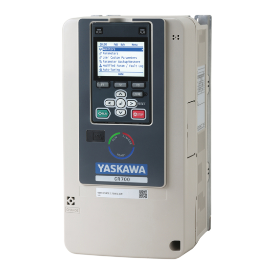
Sign In
Upload
Manuals
Brands
YASKAWA Manuals
DC Drives
CR700
YASKAWA CR700 Manuals
Manuals and User Guides for YASKAWA CR700. We have
4
YASKAWA CR700 manuals available for free PDF download: Technical Manual, Quick Start Manual, Manual
YASKAWA CR700 Technical Manual (886 pages)
Brand:
YASKAWA
| Category:
DC Drives
| Size: 56.77 MB
Table of Contents
Table of Contents
3
Preface and General Precautions
13
Receiving
14
Glossary
14
Registered Trademarks
14
Using the Product Safely
15
Explanation of Signal Words
15
Section Safety
15
Warning Label Content and Locations
17
Warranty Information
18
Exclusion of Liability
18
Receiving
19
Section Safety
20
Crane Application Instructions
21
Model Number and Nameplate Check
22
Nameplate
22
How to Read the Model Number
22
Control Method Type and Corresponding Features
26
Mechanical & Electrical Installation
29
Section Safety
30
Installation Environment
33
Installation Orientation and Spacing
34
Moving the Drive
36
Using the Hanging Brackets to Move the Drive
36
Instructions on Drive Suspension
36
Drive Watt Loss
38
Remove and Reattach the Keypad
40
Remove the Keypad
40
Reattach the Keypad
40
Install the Keypad in a Control Panel or Another Device
41
Operate the Keypad from a Remote Location
41
Connect the Keypad from a Remote Location
41
Removing/Reattaching Covers
46
Removing/Reattaching the Cover Using Procedure a
46
Removing/Reattaching the Cover Using Procedure B
47
Change the Drive Enclosure Type
51
Remove the Knock-Out Holes
51
Attach the Protective Cover (Procedure A)
51
Attach the Protective Cover (Procedure B)
53
Attach the Protective Cover (Procedure C)
55
Attach the Protective Cover (Procedure D)
56
Attach the Protective Cover (Procedure E)
58
Attach the Protective Cover (Procedure F)
61
Attach the Protective Cover (Procedure G)
64
Installation Methods
67
Electrical Installation
71
Standard Connection Diagram
71
Main Circuit Wiring
74
Motor and Main Circuit Connections
74
Configuration of Main Circuit Terminal Block
74
Main Circuit Terminal Functions
79
Main Circuit Wire Gauges and Tightening Torques
80
Main Circuit Terminal and Motor Wiring
90
Protection of Main Circuit Terminals
93
Main Circuit Terminal Block Wiring Procedure
94
Wire the Main Circuit Terminal Block with Procedure a
94
Wire the Main Circuit Terminal Block with Procedure B
97
Control Circuit Wiring
100
Control Circuit Connection Diagram
100
Control Circuit Terminal Block Functions
101
Terminal Configuration
106
Wiring the Control Circuit Terminal
108
Switches and Jumpers on the Terminal Board
110
Control I/O Connections
112
Set Sinking Mode/Sourcing Mode
112
Select Input Signals for Multi-Function Analog Input Terminals A1 to A3
112
Set Multi-Function Analog Input Terminal A3 to PTC Input
113
Select Output Signals for Multi-Function Analog Output Terminals FM, am
113
Switch on Termination Resistor for Memobus/Modbus Communications
113
Connect the Drive to a PC
115
Braking Resistor Installation
116
Installing a Braking Resistor: ERF Type
116
Installing a Braking Resistor Unit : LKEB Type
116
Installing a Braking Unit Connection: CDBR Type
117
Connect Braking Units in Parallel
123
Dynamic Braking Option Overload Protection
123
Drive Wiring Protection
125
(Rcm/Rcd)
125
Installing a Residual Current Monitoring/Detection (RCM/RCD)
125
Dynamic Braking Option, Motor Protection
126
Install an Electromagnetic Contactor (MC) at the Input Side of the Drive
126
Installing a Thermal Overload Relay on the Drive Output
126
Improve the Power Factor
128
Connect an AC Reactor or a DC Reactor
128
Prevent Switching Surge
129
Decrease Noise
130
Connect a Noise Filter to the Input Side (Primary Side)
130
Connect a Noise Filter to the Output Side (Secondary Side)
130
Protect the Drive During Failures
132
Factory-Recommended Branch Circuit Protection
132
Wiring Checklist
134
Motor Application Precautions
135
Precautions for Existing Standard Motors
135
Precautions Concerning Use of Specialized Motors
136
Notes on the Power Transmission Mechanism
136
Startup Procedure and Test Run
137
Section Safety
138
Component Names and Functions
139
LCD Display
140
Indicator Leds and Drive Status
141
Keypad Mode and Menu Displays
143
LED Status Ring
145
Keypad Operation
147
Use the HOME Screen
147
Show the Monitor
148
Set Custom Monitors
149
Show Custom Monitors
150
Set the Monitors to Show as a Bar Graph
150
Show Monitors as Bar Graphs
152
Set the Monitors to Show as Analog Gauges
152
Display Monitors as an Analog Gauge
153
Set Monitoring Items to be Shown as a Trend Plot
154
Show Monitor Items as a Trend Plot
157
Change Parameter Setting Values
158
Examine User Custom Parameters
160
Save the Backup of Parameters
161
Write Backed-Up Parameters to the Drive
162
Verify Keypad Parameters and Drive Parameters
163
Erase Parameters Backed up to the Keypad
164
Check Modified Parameters
165
Restore Modified Parameters to Defaults
166
Show Fault History
168
Auto-Tuning the Drive
168
Set the Keypad Language Display
171
Set the Date and Time
171
Disable the Initial Setup Screen
173
Start Data Logging
174
Configuring the Data Log Content
175
Set Backlight to Automatically Turn off
177
Show Information about the Drive
178
Write Automatically Backed-Up Parameters to the Drive
179
Items to Check before Starting up the Drive
180
Check before Energizing the Drive
180
Check after You Energize the Drive
180
Perform the Initial Settings
180
Control Method Selection
181
Parameter Settings for Operation Without the Brake Sequence
181
Setting the Direction of Motor Rotation
181
Setting the Encoder (Pulse Generator)
182
Application Preset
183
Test Run Procedure
185
Test Run Flowchart
186
Auto-Tuning
188
Auto-Tuning for Induction Motors
188
ASR and Inertia Tuning
189
Precautions before Auto-Tuning
190
Load Test Runs
193
Perform a No-Load Test Run
193
Crane Application Setup Procedure
194
External Interlock
194
Run Command
194
Operation When the External Baseblock Command Is Input and Cleared
194
Speed Reference
195
Brake Sequence
195
Adjusting the Run Command
204
Impact Stop Function
206
Light-Load Acceleration 1 Function
207
Light-Load Acceleration 2 Function
210
Overload Detection
213
Overtorque Detection
214
Travel Limit Function
215
Motor Switch Function
216
Parameter Switching Function for Reverse Operation
220
Crane Maintenance Monitor
221
Frequency Reduction Gain
223
Rapid Deceleration Function
224
Problems that Can Frequently Occur During Setup and Possible Solutions
226
Cannot Change Parameter Settings
227
The Correct Auto-Tuning Mode Is Not Available
227
Crane Sequence Does Not Operate
227
Motor Does Not Rotate after Entering Run Command
227
The Starting Torque Is Not Sufficient
228
Motor Does Not Restart after Power Loss
228
Motor Rotates in the Opposite Direction from the Run Command
229
Motor Rotates in One Direction Only
229
Motor Stops When Operating at the Brake Release Frequency Speed
229
Response Is Slow at Start
229
Motor Stalls During Acceleration or Accel/Decel Time Is too Long
229
Output Frequency Is Not as High as Frequency Reference
230
Drive Frequency Reference Differs from the Controller Frequency Reference
231
Command
231
Large Inconsistency in Stopping Position Due to the Load Rate
231
Deceleration Takes Longer than Expected When Dynamic Braking Is Enabled
231
The Motor Rotates after the Drive Output Is Shut off
231
Suspension Drops (Falls)
231
Load Slips at Start
232
Load Slips at Stop
232
Slipping Occurs During Extremely Fast Inching
232
Load Falls When Brake Is Applied
232
Excessive Current Occurs at Start
232
Excessive Output Current at Constant Speed
233
Too Much Output Current, Oscillation
233
Start Take too Long
233
Excessive Current Flow When Starting to Hoist Immediately after Stopping
233
Lowering
233
Brake Slips at Start
234
Brake Grinding Occurs at Stop
234
Impact Stop Is Not Available after the Motor Stops
234
Motor Keeps Rotating at the Creep Frequency During Impact Stop Operation
234
Accelerates Despite a Heavy Load When Using the Light-Load Acceleration
234
Function
234
No Acceleration Despite a Light Load When Using the Light-Load Acceleration
234
Function
235
No Acceleration Despite a Light Load When Using the Light-Load Acceleration
235
Excessive Motor Oscillation and Erratic Rotation
235
Oscillation Occurs When Lowering in a Hoist/Lowering Crane Without a
235
Counterweight
235
With a Traverse Crane
235
Unexpected Noise from Connected Machinery Occurs When Motor Rotates
235
Oscillation or Hunting Occurs When Motor Rotates
235
The Motor Is Making an Audible Noise
236
The Motor Is too Hot
236
Drive
236
Residual Current Monitoring/Detection (RCM/RCD) Trips During Run
236
Flux Compensation (Current Suppression at Start)
236
Controllability Problems and Possible Solutions
238
V/F Control and Closed Loop V/F Control
238
Open Loop Vector Control Method
238
Closed Loop Vector Control
240
AOLV Control
240
Test Run Checklist
242
Standards Compliance
245
Section Safety
246
European Standards
248
CE Low Voltage Directive Compliance
248
EMC Directive
262
UL Standards
273
Area of Use
273
Wiring to the Main Circuit Terminal
273
Low Voltage Wiring for Control Circuit Terminals
288
Drive Motor Overload and Overheat Protection
288
China Rohs Compliance
293
Information on Hazardous Substances in this Product
293
对应中国Rohs指令
294
本产品中含有有害物质的信息
294
Safe Disable Input
295
Safe Disable Specifications
295
Precautions
296
Using the Safe Disable Function
296
Network Communications
299
Section Safety
300
Field Bus Network Support
301
Memobus/Modbus Communications
302
Configure Master/Slave
302
Communication Specifications
302
Communication with the PLC
302
Drive Operations by Memobus/Modbus
304
Communications Timing
304
Message Format
305
Examples of Messages for Commands/Responses
307
Enter Command
311
Self-Diagnostics
312
Communications Data Table
313
Error Codes
332
Troubleshooting
333
Section Safety
334
Types of Faults, Minor Faults, Alarms, and Errors
336
List of Fault, Minor Fault, Alarm, and Error Codes
337
Fault
342
Minor Faults/Alarms
363
Parameter Setting Errors
373
Auto-Tuning Errors
377
Backup Function Operating Mode Display and Errors
381
Diagnosing and Resetting Faults
382
Fault and Power Loss Occur at the same Time
382
Fault Occurs Without Power Loss
382
Fault Reset Procedure
382
Periodic Inspection and Maintenance
383
Section Safety
384
Inspection
386
Recommended Daily Inspection
386
Recommended Periodic Inspection
386
Maintenance
388
Replace Cooling Fans and Circulation Fans
389
Number of Cooling Fans and Circulation Fans Used
389
Fan Replacement (Procedure A)
389
Fan Replacement (Procedure B)
391
Fan Replacement (Procedure C)
394
Fan Replacement (Procedure D)
396
Fan Replacement (Procedure E)
398
Fan Replacement (Procedure F)
400
Fan Replacement (Procedure G)
405
Replace the Drive
414
About the Control Circuit Terminal Block
414
Replace the Keypad Battery
419
Storage Guidelines
421
Disposal
423
Section Safety
424
Disposal Instructions
425
Specifications
427
Section Safety
428
Model Specifications (200 V Class)
429
Model Specifications (400 V Class)
431
Drive Specifications
434
Drive Derating
437
Carrier Frequency Settings and Rated Current Values
437
Altitude Derating
438
Drive Exterior and Mounting Dimensions
439
IP20/UL Open Type
439
IP20/UL Type 1
448
Knock-Out Hole Dimensions (UL Type 1)
457
Peripheral Devices and Options
461
Parameter List
465
Section Safety
466
How to Read the Parameter List
467
Icons and Terms that Identify Parameters and Control Methods
467
Parameter Groups
468
A: Initialization Parameters
469
A1: Initialization
469
A2: User Parameters
470
B: Application
471
B1: Operation Mode Selection
471
B2: DC Injection Braking
472
B4: Timer Function
472
B7: Droop Control
473
B9: Zero Servo
473
C: Tuning
474
C1: Accel & Decel Time
474
C2: S-Curve Characteristics
475
C3: Slip Compensation
475
C4: Torque Compensation
476
C5: Auto Speed Regulator (ASR)
477
C6: Carrier Frequency
478
D: Reference Settings
479
D1: Frequency Reference
479
D2: Reference Limits
480
D3: Jump Frequency
480
D4: Frequency Ref Up/Down & Hold
480
D6: Field Forcing
481
D7: Offset Frequency
481
E: Motor Parameters
482
E1: V/F Pattern for Motor 1
482
E2: Motor Parameters
483
E3: V/F Pattern for Motor 2
484
E4: Motor 2 Parameters
485
E7: Motor 3 Parameters
485
F: Options
487
F1: Encoder Option Setup
487
F2: Analog Input Option
488
F3: Digital Input Option
489
F4: Analog Output Option
490
F5: Digital Output Option
490
F6: Communication Options
491
F7: Communication Options
494
10.10 H: Terminal Functions
499
H1: Digital Inputs
499
H2: Digital Outputs
503
H3: Analog Inputs
509
H4: Analog Outputs
511
H5: Memobus/Modbus Communications
512
H7: Virtual Inputs / Outputs
513
10.11 L: Protection Functions
515
L1: Motor Protection
515
L2: Power Loss Ride through
515
L3: Stall Prevention
516
L4: Speed Detection
517
L7: Torque Limit
518
L8: Hardware Protection
518
L9: Drive Protection 2
520
10.12 N: Special Adjustment
521
N1: Hunting Prevention
521
N2: Auto Freq Regulator (AFR)
521
N3: Overexcitation Deceleration
522
N4: Adv Open Loop Vector Tune
522
N5: Feed Forward Control
523
N6: Online Resistance Tuning
523
10.13 O: Keypad-Related Settings
524
O1: Keypad Display
524
O2: Keypad Operation
526
O3: Copy Keypad Function
527
O4: Maintenance Monitors
527
O5: Log Function
528
10.14 S: Crane Parameters
530
S1: Brake Sequence
530
S2: Run Command Tuning, Maintenance Monitors, Frequency Derating Gain, Rapid
532
Deceleration
532
S3: Impact Stop
533
S4: Light-Load Acceleration
533
S5: Overload Detection
535
S6: Overtorque Detection
535
10.15 T: Motor Tuning
537
T0: Tuning Mode Selection
537
T1: Induction Motor Auto-Tuning
537
T3: ASR and Inertia Tuning
538
10.16 U: Monitors
539
U1: Operation Status Monitors
539
U2: Fault Trace
541
U3: Fault History
543
U4: Maintenance Monitors
544
U6: Operation Status Monitors
548
Parameters that Change from the Default Settings with A1-02
551
Selection
551
Parameters that Change from the Default Settings with E3-01
554
Mode Selection]
554
Parameters Changed by E1-03 [V/F Pattern Selection]
555
Parameters Changed by O2-04 [Drive Model (KVA) Selection]
557
Class
557
Class
561
Parameter Details
567
Section Safety
568
A: Initialization Parameters
569
A1: Initialization
569
A2: User Parameters
582
B: Application
584
B1: Operation Mode Selection
584
B2: DC Injection Braking
593
B4: Timer Function
595
Advertisement
YASKAWA CR700 Technical Manual (773 pages)
AC Drive For Cranes 200/400 V class: 0.4 to 110/315 kW
Brand:
YASKAWA
| Category:
DC Drives
| Size: 78.88 MB
Table of Contents
Table of Contents
3
Preface and General Precautions
13
Receiving
13
Glossary
13
Registered Trademarks
13
Using the Product Safely
14
Supplemental Safety Information
14
General Safety
14
Warning Label Content and Locations
15
Warranty Information
15
Warranty Period
15
Warranty Scope
15
Warranty and Exclusion of Liability
16
Receiving
17
Section Safety
17
Crane Application Instructions
17
Model Number and Nameplate Check
17
Nameplate
18
How to Read Model Numbers
18
Control Method Type and Corresponding Features
21
Mechanical & Electrical Installation
23
General Safety
23
Installation Environment
24
Installation Orientation and Spacing
25
Moving the Drive
26
Using the Hanging Brackets to Move the Drive
27
Instructions on Drive Suspension
27
Drive Watt Loss
28
Remove and Reattach the Keypad
29
Remove the Keypad
29
Reattach the Keypad
30
Install the Keypad to a Control Panel or Another Device
30
Operate the Keypad Apart from the Drive
30
Connect the Keypad from a Remote Location
30
Removing/Reattaching Covers
35
Removing/Reattaching the Cover Using Procedure a
35
Removing/Reattaching the Cover Using Procedure B
36
Change the Drive Enclosure Type
39
Attach the Protective Cover (Procedure A)
39
Attach the Protective Cover (Procedure B)
41
Attach the Protective Cover (Procedure C)
42
Attach the Protective Cover (Procedure D)
45
Attach the Protective Cover (Procedure E)
47
Attach the Protective Cover (Procedure F)
49
Installation Procedure
51
Electrical Installation
55
Standard Connection Diagram
55
Main Circuit Wiring
57
Motor and Main Circuit Connections
58
Configuration of Main Circuit Terminal Block
58
Main Circuit Terminal Functions
63
Wire Gauges and Tightening Torques
63
Main Circuit Terminal and Motor Wiring
76
Protection of Main Circuit Terminals
79
Wiring Procedure for the Main Circuit Terminal Block
80
Control Circuit Wiring
85
Control Circuit Connection Diagram
85
Control Circuit Terminal Block Functions
87
Terminal Configuration
90
Wiring the Control Circuit Terminal
92
Switches and Jumpers on the Terminal Board
94
Control I/O Connections
95
Setting Sink Mode/Source Mode
95
Select Input Signals for Multi-Function Analog Input Terminals A1 to A3
96
Set Multi-Function Analog Input Terminal A3 to PTC Input
96
Select Output Signals for Multi-Function Analog Output Terminals FM, am
97
Switch on Termination Resistor for Memobus/Modbus Communications
97
Connect the Drive to a PC
97
Braking Resistor Installation
98
Installing a Braking Resistor: ERF Type
98
Installing a Braking Resistor Unit : LKEB Type
99
Installing a Braking Unit Connection: CDBR Type
99
Connect Braking Units in Parallel
105
Dynamic Braking Option Overload Protection
105
Drive Wiring Protection
106
(Elcb)
106
Install an Earth Leakage Circuit Breaker
106
Dynamic Braking Option, Motor Protection
107
Install an Electromagnetic Contactor (MC) at Input Side of Drive
107
Install a Thermal Overload Relay on the Drive Output
107
Improve the Power Factor
108
Connect an AC Reactor or a DC Reactor
108
Prevent Switching Surge
109
Decrease Noise
109
Connect a Noise Filter to the Input Side (Primary Side)
109
Connect a Noise Filter to the Output Side (Secondary Side)
110
Protect the Drive During Failures
111
Factory Recommended Branch Circuit Protection
111
Wiring Checklist
113
Motor Application Precautions
114
Precautions for Existing Standard Motors
114
Precautions Concerning Use of Specialized Motors
115
Notes on the Power Transmission Mechanism
116
Startup Procedure and Test Run
116
General Safety
116
Component Names and Functions
117
LCD Display
119
Indicator Leds and Drive Status
120
Keypad Mode and Menu Displays
121
LED Status Ring
122
Keypad Operation
123
Use the HOME Screen
123
Show the Standard Monitor
124
Set Custom Monitors
125
Show Custom Monitors
126
Set the Monitors to Show as a Bar Graph
127
Show Monitors as Bar Graphs
128
Set the Monitors to Show as Analog Gauges
129
Display Monitors as an Analog Gauge
130
Set Monitoring Items to be Shown as a Trend Plot
131
Show Monitor Items as a Trend Plot
134
Change Parameter Settings
135
Examine User Custom Parameters
136
Save the Backup of Parameters
137
Write Backed-Up Parameters to the Drive
138
Verify Keypad Parameters and Drive Parameters
140
Erase Parameters Backed up to the Keypad
141
Check Modified Parameters
142
Restore Modified Parameters to Defaults
143
Show Fault History
144
Auto-Tuning the Drive
145
Set the Keypad Language Display
147
Set the Date and Time
148
Disable the Initial Setup Screen
150
Start Data Logging
150
Set Data to Log
151
Set Backlight to Automatically Turn off
153
Display Drive Information
155
Write Automatically Backed-Up Parameters to the Drive
156
Items to Check before Starting up the Drive
156
Check before Energizing the Drive
156
Check after Energizing the Drive
157
Perform the Initial Settings
157
Control Method Selection
158
Parameter Settings for Operation Without the Brake Sequence
158
Setting the Direction of Motor Rotation
158
Setting the Encoder (Pulse Generator)
158
Application Preset
159
Test Run Procedure
160
Test Run Flowchart
162
Auto-Tuning
163
Auto-Tuning for Induction Motors
163
ASR and Inertia Tuning
165
Precautions before Auto-Tuning
166
Load Test Runs
168
Perform a No-Load Test Run
169
Crane Application Setup Procedure
169
External Interlock
169
Run Command
170
Operation When the External Baseblock Command Is Input and Cleared
170
Speed Reference
170
Brake Sequence
171
Adjusting the Run Command
180
Impact Stop Function
182
Light-Load Acceleration 1 Function
183
Light-Load Acceleration 2 Function
186
Overload Detection
190
Overtorque Detection
191
Travel Limit Function
192
Motor Switch Function
193
Parameter Switching Function for Reverse Operation
197
Crane Maintenance Monitor
199
Frequency Reduction Gain
201
Rapid Deceleration Function
202
Problems that Can Frequently Occur During Setup and Possible Solutions
203
Cannot Change Parameter Settings
204
The Correct Auto-Tuning Mode Is Not Available
205
Crane Sequence Does Not Operate
205
Motor Does Not Rotate after Entering Run Command
205
The Starting Torque Is Not Sufficient
206
Motor Does Not Restart after Power Loss
206
Motor Rotates in the Opposite Direction from the Run Command
206
Motor Rotates in One Direction Only
206
Motor Stops When Operating at the Brake Release Frequency Speed
207
Response Is Slow at Start
207
Motor Stalls During Acceleration or Accel/Decel Time Is too Long
207
Output Frequency Is Not as High as Frequency Reference
208
Drive Frequency Reference Differs from the Controller Frequency Reference
209
Command
209
Large Inconsistency in Stopping Position Due to the Load Rate
209
Deceleration Takes Longer than Expected When Dynamic Braking Is Enabled
209
The Motor Rotates after the Drive Output Is Shut off
209
Suspension Drops (Falls)
210
Load Slips at Start
210
Load Slips at Stop
210
Slipping Occurs During Extremely Fast Inching
210
Load Falls When Brake Is Applied
211
Excessive Current Occurs at Start
211
Excessive Output Current at Constant Speed
211
Too Much Output Current, Oscillation
211
Despite Measures to Increase Flux, Brake Operation Is Slow and Peak Current at Start Take too Long
212
Excessive Current Flow When Starting to Hoist Immediately after Stopping
212
Lowering
212
Brake Slips at Start
212
Brake Grinding Occurs at Stop
212
Impact Stop Is Not Available after the Motor Stops
212
Motor Keeps Rotating at the Creep Frequency During Impact Stop Operation
213
Accelerates Despite a Heavy Load When Using the Light-Load Acceleration
213
Function
213
No Acceleration Despite a Light Load When Using the Light-Load Acceleration
213
Excessive Motor Oscillation and Erratic Rotation
214
Oscillation Occurs When Lowering in a Hoist/Lowering Crane Without a
214
Counterweight
214
With a Traverse Crane
214
Unexpected Noise from Connected Machinery Occurs When Motor Rotates
214
Oscillation or Hunting Occurs When Motor Rotates
214
The Motor Is Making an Audible Noise
214
The Motor Is too Hot
215
There Is Audible Noise from the Drive or Motor Cables When the Drive Is Energized
215
Earth Leakage Circuit Breaker (ELCB) Trips During Run
215
Flux Compensation (Current Suppression at Start)
215
Controllability Problems and Possible Solutions
216
V/F Control and Closed Loop V/F Control
217
Open Loop Vector Control Method
218
Closed Loop Vector Control
221
AOLV Control
222
Test Run Checklist
223
Standards Compliance
225
General Safety
225
European Standards
226
EU Declaration of Conformity
227
CE Low Voltage Directive Compliance
228
EMC Directive
245
UL Standards
255
Area of Use
255
Wiring to the Main Circuit Terminal
255
Low Voltage Wiring for Control Circuit Terminals
275
Drive Motor Overload and Overheat Protection
275
China Rohs Compliance
279
Information on Hazardous Substances in this Product
279
对应中国Rohs指令
280
本产品中含有有害物质的信息
280
Safe Disable Input
280
Safe Disable Specifications
281
Precautions
281
Using the Safe Disable Function
282
Network Communications
284
Safety Precautions
284
Field Bus Network Support
284
Memobus/Modbus Communications
284
Configure Master/Slave
284
Communication Specifications
285
Communication with the PLC
285
Drive Operations by Memobus/Modbus
287
Communications Timing
287
Message Format
288
Examples of Messages for Commands/Responses
290
Enter Command
294
Self-Diagnostics
295
Communications Data Table
295
Error Codes
316
Troubleshooting
317
General Safety
317
Types of Faults, Minor Faults, Alarms, and Errors
318
List of Fault, Minor Fault, Alarm, and Error Codes
319
Faults
324
Minor Faults/Alarms
338
Parameter Setting Errors
346
Auto-Tuning Errors
351
Backup Function Operating Mode Display and Errors
355
Diagnosing and Resetting Faults
356
Fault and Power Loss Occur at the same Time
356
Fault Occurs Without Power Loss
356
Fault Reset Procedure
356
Periodic Inspection and Maintenance
357
General Safety
357
Inspection
358
Recommended Daily Inspection
358
Recommended Periodic Inspection
359
Maintenance
360
Replace a Cooling Fan and Circulation Fan
362
Number of Cooling Fans and Circulation Fans Used
362
Replace a Fan (Procedure A)
363
Replace a Fan (Procedure B)
365
Replace a Fan (Procedure C)
367
Replace a Fan (Procedure D)
369
Replace a Fan (Procedure E)
372
Replace Fans (Procedure F)
374
Replace Fans (Procedure G)
380
Replace the Drive
388
About the Control Circuit Terminal Block
388
Replace the Keypad Battery
393
Storage Guidelines
394
Disposal
395
Section Safety
395
Disposal Instructions
395
Specifications
395
Safety Precautions
395
Model Specifications (200 V Class)
396
Model Specifications (400 V Class)
397
Drive Specifications
400
Drive Derating
403
Carrier Frequency Settings and Rated Current Value
403
Altitude Derating
404
Drive Exterior and Mounting Dimensions
405
Open Chassis Type (IP20)
405
Enclosed Wall-Mounted Type (UL Type 1)
413
Knock-Out Hole Dimensions (UL Type 1)
419
Peripheral Devices and Options
423
Parameter List
427
Section Safety
427
How to Read the Parameter List
428
Icons and Terms Used to Represent Control Modes
428
Parameter Groups
428
A: Initialization Parameters
429
A1: Initialization
429
A2: User Parameters
430
B: Application
430
B1: Operation Mode Selection
430
B2: DC Injection Braking
432
B4: Timer Function
432
B7: Droop Control
433
B9: Zero Servo
433
C: Tuning
433
C1: Accel & Decel Time
433
C2: S-Curve Characteristics
434
C3: Slip Compensation
435
C4: Torque Compensation
436
C5: Auto Speed Regulator (ASR)
436
C6: Duty & Carrier Frequency
438
D: Reference Settings
439
D1: Frequency Reference
439
D2: Reference Limits
439
D3: Jump Frequency
440
D4: Frequency Ref Up/Down & Hold
440
D6: Field Forcing
440
D7: Offset Frequency
440
E: Motor Parameters
441
E1: V/F Pattern for Motor 1
441
E2: Motor Parameters
442
E3: V/F Pattern for Motor 2
443
E4: Motor 2 Parameters
444
E7: Motor 3 Parameters
445
F: Options
446
F1: PG Option Setup (Encoder)
446
F2: Analog Input Option
448
F3: Digital Input Option
448
F4: Analog Monitor Option
449
F5: Digital Output Option
450
F6: Communication Options
451
F7: Ethernet Options
454
H: Terminal Functions
457
H1: Digital Inputs
457
H2: Digital Outputs
461
H3: Analog Inputs
468
H4: Analog Outputs
471
H5: Memobus/Modbus Communications
472
H7: Virtual Inputs / Outputs
473
L: Protection Functions
474
L1: Motor Protection
474
L2: Power Loss Ride through
475
L3: Stall Prevention
475
L4: Speed Detection
477
L7: Torque Limit
477
L8: Hardware Protection
478
L9: Drive Protection 2
480
N: Special Adjustment
480
N1: Hunting Prevention
480
N2: Auto Freq Regulator (AFR)
481
N3: Overexcitation Braking
481
N4: Adv Open Loop Vector Tune
482
N5: Feed Forward Control
483
N6: Online Tuning
483
O: Keypad-Related Settings
483
O1: Keypad Display
483
O2: Keypad Operation
486
O3: Copy Keypad Function
487
O4: Maintenance Monitors
488
O5: Log Function
489
S: Crane Parameters
490
S1: Brake Sequence
490
S2: Run Command Tuning, Maintenance Monitors, Frequency Derating Gain, Rapid
492
Deceleration
492
S3: Impact Stop
493
S4: Light-Load Acceleration
493
S5: Overload Detection
495
S6: Overtorque Detection
496
T: Motor Tuning
496
T0: Tuning Mode Selection
496
T1: Induction Motor Auto-Tuning
497
T3: ASR and Inertia Tuning
498
U: Monitors
498
YASKAWA CR700 Quick Start Manual (128 pages)
AC Drive
Brand:
YASKAWA
| Category:
Media Converter
| Size: 22.5 MB
Table of Contents
Table of Contents
3
1 General Information
6
2 Safety
6
Explanation of Signal Words
6
General Safety Instructions
6
Intended Use
8
Warranty Information
8
Exclusion of Liability
8
3 Moving the Drive
8
4 Receiving
9
How to Read the Model Number
9
Rated Output Current
11
5 Component Names and Functions
12
Keypad Mode and Menu Displays
14
6 LED Status Ring
15
7 Start-Up Procedure
16
8 Mechanical Installation
16
Installation Orientation and Spacing
16
Using the Hanging Brackets to Move the Drive
18
Removing/Reattaching Covers
19
Removing/Reattaching the Cover Using Procedure a
19
Removing/Reattaching the Cover Using Procedure B
20
9 Electrical Installation
23
Standard Connection Diagram
23
Main Circuit Terminal Block Wiring Procedure
25
Wire the Main Circuit Terminal Block with Procedure a
26
Wire the Main Circuit Terminal Block with Procedure B
29
Main Circuit Terminal Functions
30
Main Circuit Wire Gauges and Tightening Torques
31
Main Circuit Wire Gauges and Tightening Torques
32
Motor and Main Circuit Connections
41
Control Circuit Terminal Block Functions
42
Input Terminals
42
Output Terminals
43
External Power Supply Input Terminals
44
Serial Communication Terminals
44
Terminal Configuration
45
Control Circuit Wire Gauges and Tightening Torques
45
Wiring the Control Circuit Terminal
46
Switches and Jumpers on the Terminal Board
48
Control I/O Connections
49
Set Sinking Mode/Sourcing Mode
49
Select Input Signals for Multi-Function Analog Input Terminals A1 to A3
50
Set Multi-Function Analog Input Terminal A3 to PTC Input
50
Switch on Termination Resistor for Memobus/Modbus Communications
51
10 Drive Start-Up
51
Setup Wizard
51
Change Parameter Setting Values
52
Disable the Initial Setup Screen
53
11 Maintenance
54
12 Drive Control, Duty Modes, and Programming
54
Application Preset
54
Control Method Selection
55
Auto-Tuning
56
Drive Parameters
57
13 Troubleshooting
59
Fault
59
Minor Faults/Alarms
67
Parameter Setting Errors
71
Auto-Tuning Errors
73
Backup Function Operating Mode Display and Errors
74
14 Drive Specifications
75
15 European Standards
77
CE Low Voltage Directive Compliance
77
Area of Use
77
Guarding against Debris
77
Wiring Diagram
78
Wire Gauges and Tightening Torques
79
Connect a Fuse to the Input Side (Primary Side)
88
CE Standards Compliance for DC Power Supply Input
89
EMC Directive
91
Install a Drive to Conform to the EMC Directive
91
Installing the External EMC Noise Filter
98
DC Reactor
101
16 UL Standards
102
Area of Use
102
Wiring to the Main Circuit Terminal
102
Notes on Wiring the Main Circuit Terminal Block
102
Wire Gauges and Tightening Torques
104
Closed-Loop Crimp Terminals
113
Factory-Recommended Branch Circuit Protection
115
Low Voltage Wiring for Control Circuit Terminals
117
Drive Motor Overload and Overheat Protection
117
E2-01: Motor Rated Current (FLA)
118
L1-01: Motor Overload (Ol1) Protection
118
L1-02: Motor Overload Protection Time
120
L1-03: Motor Thermistor Oh Alarm Select
120
L1-04: Motor Thermistor Oh Fault Select
121
Advertisement
YASKAWA CR700 Manual (69 pages)
Brand:
YASKAWA
| Category:
DC Drives
| Size: 4.13 MB
Table of Contents
Smartphone Application
13
Wireless Access
13
Basic Instructions
17
Standard Specifications
20
Common Specifications
22
Standard Connection Diagram
24
Terminal Specifi Cations
26
Terminal Functions
26
Main Circuit Terminals
26
Option Cards
37
Ground Fault Interrupter
38
Circuit Breaker
38
Magnetic Contactor
39
Connection Diagram
40
Zero Phase Reactor
43
Fuse and Fuse Holder
44
Input Noise Filter
46
Dynamic Braking Option
49
LED Keypad
56
Potential Transformer
59
Application Notes
60
Installation
60
General Handling
61
Peripheral Devices
63
Notes on Motor Operation
65
Applications with Specialized Motors
66
Advertisement
Related Products
YASKAWA CIMR-E7U20P7
YASKAWA CIMR-E7U2030
YASKAWA CIMR-E7U2110
YASKAWA CIMR-P7 series
YASKAWA CIMR-P7U-2018-107
YASKAWA CIMR-P7U-43P7-107
YASKAWA CIMR-P7U-47P5-107
YASKAWA CIMR-P7U-4110-107
YASKAWA L1000V CIMR-LC4V0015F
YASKAWA CIPR-GA50U2030AJ Series
YASKAWA Categories
Controller
DC Drives
Servo Drives
Robotics
Control Unit
More YASKAWA Manuals
Login
Sign In
OR
Sign in with Facebook
Sign in with Google
Upload manual
Upload from disk
Upload from URL