
Related Manuals for YASKAWA CR700


Summary of Contents for YASKAWA CR700
- Page 1 YASKAWA AC Drive CR700 For Cranes Quick Start Guide Type: CIPR-CR70Cxxxxxxxx Models: 200 V Class, Three-Phase Input: 0.4 to 110 kW 400 V Class, Three-Phase Input: 0.4 to 315 kW...
- Page 2 This Page Intentionally Blank YASKAWA TOEPC71061723A YASKAWA AC Drive CR700 Quick Start Guide...
-
Page 3: Table Of Contents
External Power Supply Input Terminals ........44 YASKAWA TOEPC71061723A YASKAWA AC Drive CR700 Quick Start Guide... - Page 4 Low Voltage Wiring for Control Circuit Terminals ....... 117 YASKAWA TOEPC71061723A YASKAWA AC Drive CR700 Quick Start Guide...
- Page 5 Revision History..........127 YASKAWA TOEPC71061723A YASKAWA AC Drive CR700 Quick Start Guide...
-
Page 6: General Information
Yaskawa's warranty for the product. Note: Failure to obey the safety messages in the manual can cause serious injury or death. Yaskawa is not responsible for injuries or damage to equipment caused by ignoring the safety messages. - Page 7 OFF. Then check the wiring and peripheral device ratings to find the cause of the problem. If you do not know the cause of the problem, contact Yaskawa before you energize the drive or peripheral devices. If you do not fix the problem before you operate the drive or peripheral devices, it can cause serious injury or death.
-
Page 8: Intended Use
Electrical Shock Hazard. Do not modify the drive body or drive circuitry. Modifications to drive body and circuitry can cause serious injury or death, will cause damage to the drive, and will void the warranty. Yaskawa is not responsible for modifications of the product made by the user. -
Page 9: Receiving
"MODEL" section of the drive nameplate to make sure that you received the correct model. 3. Make sure that the product and motor combinations are correct. Contact your supplier or Yaskawa sales office if you received an incorrect drive model or if the drive does not operate correctly. - Page 10 • B: LCD keypad (humidity-resistant and dust-resistant) • D: Bluetooth LCD keypad • E: Bluetooth LCD keypad (humidity-resistant and dust-resistant) • F: LED keypad • G: LED keypad (humidity-resistant and dust-resistant) Special applications A: Standard YASKAWA TOEPC71061723A YASKAWA AC Drive CR700 Quick Start Guide...
-
Page 11: Rated Output Current
4 Receiving This certification is not available in all regions where you will use the device. Contact Yaskawa or your nearest sales representative for more information. ■ Rated Output Current These tables give the rated output current values. Note: • These output current values are applicable for drives that operate at the default settings. -
Page 12: Component Names And Functions
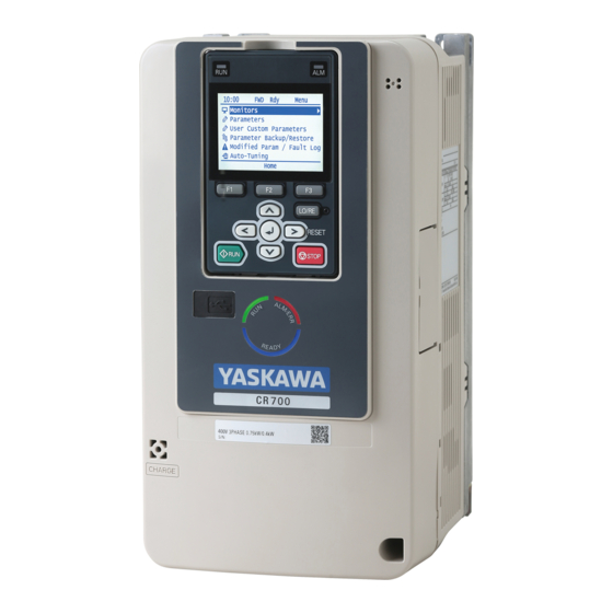
5 Component Names and Functions Maximum Applicable Motor Output Rated Output Current Symbol Component Names and Functions Figure 5.1 Keypad YASKAWA TOEPC71061723A YASKAWA AC Drive CR700 Quick Start Guide... - Page 13 Displays keypad model, lot number, and FLASH number. Note: Nameplate Keypads with FLASH number of 1002 or later can be used. Keypads with FLASH number of 1001 or earlier may not display messages properly. YASKAWA TOEPC71061723A YASKAWA AC Drive CR700 Quick Start Guide...
-
Page 14: Keypad Mode And Menu Displays
5 Component Names and Functions ◆ Keypad Mode and Menu Displays Figure 5.2 Keypad Functions and Display Levels YASKAWA TOEPC71061723A YASKAWA AC Drive CR700 Quick Start Guide... -
Page 15: Led Status Ring
• The drive detects a fault. • There is no fault and the drive received a Run command, but the drive cannot operate (such as when in Programming Mode, or when is flashing). YASKAWA TOEPC71061723A YASKAWA AC Drive CR700 Quick Start Guide... -
Page 16: Start-Up Procedure
The drive is prepared to run the operation. Mechanical Installation This section gives information about the standard environment for correct installation. ◆ Installation Orientation and Spacing Install the drive vertically for sufficient cooling airflow. YASKAWA TOEPC71061723A YASKAWA AC Drive CR700 Quick Start Guide... - Page 17 8 Mechanical Installation Note: Contact Yaskawa or your nearest sales representative for details about the drive models that can be installed on its side and their operating conditions. A - Upright installation B - Horizontal installation Figure 8.1 Installation Orientation ■...
-
Page 18: Using The Hanging Brackets To Move The Drive
Crush Hazard. When you install the drive, do not hold the front cover. Install the drive with holding the heatsink. If you hold the front cover, the cover will come off and the drive will fall, then it can cause injury. YASKAWA TOEPC71061723A YASKAWA AC Drive CR700 Quick Start Guide... -
Page 19: Removing/Reattaching Covers
A - Keypad C - Holder B - Keypad connector Figure 8.5 Remove the Keypad and Keypad Connector Loosen the front cover screws. Figure 8.6 Loosen the Front Cover Screws YASKAWA TOEPC71061723A YASKAWA AC Drive CR700 Quick Start Guide... -
Page 20: Removing/Reattaching The Cover Using Procedure B
A - Keypad C - Connector holder B - Keypad connector Figure 8.9 Remove the Terminal Cover, Keypad, and Keypad Connector YASKAWA TOEPC71061723A YASKAWA AC Drive CR700 Quick Start Guide... - Page 21 Wire the grounding terminals first, main circuit terminals next, and control circuit terminals last. Move the front cover to connect the hooks at the top of the front cover to the drive. A - Hooks Figure 8.13 Reattach the Front Cover YASKAWA TOEPC71061723A YASKAWA AC Drive CR700 Quick Start Guide...
- Page 22 • Make sure that you do not pinch wires or signal lines between the wiring cover and the drive before you reattach the cover. • Tighten the screws to a tightening torque of 0.98 N∙m to 1.33 N∙m (8.67 lbf∙in to 11.77 lbf∙in). YASKAWA TOEPC71061723A YASKAWA AC Drive CR700 Quick Start Guide...
-
Page 23: Electrical Installation
Motor winding and insulation failure can occur. Note: Do not connect the AC control circuit ground to the drive enclosure. Incorrect ground wiring can cause the control circuit to operate incorrectly. YASKAWA TOEPC71061723A YASKAWA AC Drive CR700 Quick Start Guide... - Page 24 9 Electrical Installation Figure 9.1 Standard Drive Connection Diagram YASKAWA TOEPC71061723A YASKAWA AC Drive CR700 Quick Start Guide...
-
Page 25: Main Circuit Terminal Block Wiring Procedure
A junction terminal is necessary to connect wires that are less than the applicable gauge to the drive. Contact Yaskawa or your nearest sales representative for more information about selection and installation of the junction terminal. -
Page 26: Wire The Main Circuit Terminal Block With Procedure A
• If you use power tools to tighten the terminal screws, use a low speed setting (300 to 400 r/min). • Users can purchase wiring tools from Yaskawa. Contact Yaskawa or your nearest sales representative for more information. - Page 27 Remove the keypad and front cover before wiring the main circuit terminal block. Pull the wiring cover away from the drive to remove it. A - Wiring cover Figure 9.5 Remove the Wiring Cover YASKAWA TOEPC71061723A YASKAWA AC Drive CR700 Quick Start Guide...
- Page 28 • Make sure that the clipped section does not cause damage to the wires. • If you use wires that are not specified by Yaskawa, the protective enclosure could lose its IP20 protective level, although the wiring cover is correct. Contact Yaskawa or your nearest sales representative for more information.
-
Page 29: Wire The Main Circuit Terminal Block With Procedure B
• After the wiring, do not twist or shake the electrical wires too much. • Be sure to use only wires with the correct size, stripped wire length, and tightening torque as specified by Yaskawa. • Use tools that fit the shape of the screw head to tighten and loosen the terminal block screws. -
Page 30: Main Circuit Terminal Functions
• Make sure that the clipped section does not cause damage to the wires. • Although the wiring cover is correct, if you use wires that are not specified by Yaskawa, the drive will not keep its IP20 protective level. -
Page 31: Main Circuit Wire Gauges And Tightening Torques
2115 and 4002 to 4150). Use terminals +3 and - to connect braking units to drives that do not have built-in braking transistors. • Refer to “Yaskawa AC Drive Option Braking Unit, Braking Resistor Unit Instruction Manual (TOBPC72060001)” for information about wire gauges and tightening torques to connect braking resistor units or braking units. -
Page 32: Main Circuit Wire Gauges And Tightening Torques
• Refer to the instruction manual for each device for recommended wire gauges to connect peripheral devices or options to terminals +1, +2, +3, -, B1, and B2. Contact Yaskawa or your nearest sales representative if the recommended wire gauges for the peripheral devices or options are out of the range of the applicable gauges for the drive. - Page 33 (2 - 22) (19.8 - 22) 2 - 5.5 1.5 - 1.7 B1, B2 Slotted (-) (2 - 5.5) (13.5 - 15) 5.5 - 8 2.0 - 2.5 Phillips/slotted combo (17.7 - 22.1) YASKAWA TOEPC71061723A YASKAWA AC Drive CR700 Quick Start Guide...
- Page 34 (89 - 107) 8 - 30 3 - 3.5 B1, B2 Slotted (-) (8 - 30) (27 - 31) 22 - 38 5.4 - 6.0 Hex bolt (+) (47.8 - 53.1) YASKAWA TOEPC71061723A YASKAWA AC Drive CR700 Quick Start Guide...
- Page 35 (150 × 2P) (310) 38 - 150 × 2P 80 × 2P Hex self-locking nut (150 × 2P) (310) 38 - 200 32 - 40 Hex bolt (slotted) (283 - 354) YASKAWA TOEPC71061723A YASKAWA AC Drive CR700 Quick Start Guide...
- Page 36 (2 - 22) (19.8 - 22) 2 - 5.5 1.5 - 1.7 B1, B2 Slotted (-) (2 - 5.5) (13.5 - 15) 2 - 8 1.2 - 1.5 Phillips/slotted combo (10.6 - 13.3) YASKAWA TOEPC71061723A YASKAWA AC Drive CR700 Quick Start Guide...
- Page 37 (2 - 22) (19.8 - 22) 2 - 5.5 1.5 - 1.7 B1, B2 Slotted (-) (2 - 5.5) (13.5 - 15) 3.5 - 8 2.0 - 2.5 Phillips/slotted combo (17.7 - 22.1) YASKAWA TOEPC71061723A YASKAWA AC Drive CR700 Quick Start Guide...
- Page 38 (19.8 - 22) 2 - 14 1.5 - 1.7 B1, B2 Slotted (-) (2 - 14) (13.5 - 15) 14 - 38 5.4 - 6.0 Hex bolt (+) (47.8 - 53.1) YASKAWA TOEPC71061723A YASKAWA AC Drive CR700 Quick Start Guide...
- Page 39 (100 - 125 × 2P) (177) 22 - 60 × 2P 38 × 2P Hex self-locking nut (50 - 60 × 2P) (177) 22 - 200 18 - 23 Hex bolt (slotted) (159 - 204) YASKAWA TOEPC71061723A YASKAWA AC Drive CR700 Quick Start Guide...
- Page 40 (150 × 4P) (310) 30 - 125 × 4P 80 × 4P Hex self-locking nut (100 - 125 × 4P) (310) 50 - 150 32 - 40 Hex bolt (slotted) (283 - 354) YASKAWA TOEPC71061723A YASKAWA AC Drive CR700 Quick Start Guide...
-
Page 41: Motor And Main Circuit Connections
Electrical Shock Hazard. Do not connect terminals R/L1, S/L2, T/L3, U/T1, V/T2, W/T3, -, +1, +2, +3, B1, or B2 to the ground terminal. If you connect these terminals to earth ground, it can cause damage to the drive or serious injury or death. YASKAWA TOEPC71061723A YASKAWA AC Drive CR700 Quick Start Guide... -
Page 42: Control Circuit Terminal Block Functions
If you frequently energize and de-energize the drive, it can cause drive failure. ■ Input Terminals Refer to Table 9.4 for a list of input terminals and functions. Text in parenthesis indicates the default setting for each multi-function output. YASKAWA TOEPC71061723A YASKAWA AC Drive CR700 Quick Start Guide... -
Page 43: Output Terminals
E (G) Shielded cable ■ Output Terminals Refer to Table 9.5 Table 9.6 for a list of output terminals and functions. Text in parenthesis indicates the default setting for each multi-function output. YASKAWA TOEPC71061723A YASKAWA AC Drive CR700 Quick Start Guide... -
Page 44: External Power Supply Input Terminals
• MEMOBUS/Modbus communication protocol Communication Modbus Communication Set DIP switch S2 to ON to enable the • Maximum 115.2 kbps output (-) termination resistor in the last drive in a MEMOBUS/Modbus network. Shield ground YASKAWA TOEPC71061723A YASKAWA AC Drive CR700 Quick Start Guide... -
Page 45: Terminal Configuration
Use the tables in this section to select the correct wires. Use shielded wire to wire the control circuit terminal block. Use crimp ferrules on the wire ends to make the wiring procedure easier and more reliable. YASKAWA TOEPC71061723A YASKAWA AC Drive CR700 Quick Start Guide... -
Page 46: Wiring The Control Circuit Terminal
When you remove the LED Status Board from the drive bracket, make sure that you temporarily install it in the holding position provided on the drive. If you cause damage to the LED status ring board, the LEDs will not function correctly. YASKAWA TOEPC71061723A YASKAWA AC Drive CR700 Quick Start Guide... - Page 47 • Do not use control circuit wiring that is longer than 50 m (164 ft) to supply the analog frequency reference from a remote source. If the control circuit wiring is too long, it can cause unsatisfactory system performance. YASKAWA TOEPC71061723A YASKAWA AC Drive CR700 Quick Start Guide...
-
Page 48: Switches And Jumpers On The Terminal Board
The terminal board is equipped with several switches used to adapt the drive I/Os to the external control signals as shown in the Figure 9.28. Set the switches to select the functions for the respective terminals. YASKAWA TOEPC71061723A YASKAWA AC Drive CR700 Quick Start Guide... -
Page 49: Control I/O Connections
Damage to Equipment. Do not close the circuit between terminals SP-SN. If you close the circuits between terminals SC-SP and terminals SC-SN at the same time, it will cause damage to the drive. YASKAWA TOEPC71061723A YASKAWA AC Drive CR700 Quick Start Guide... -
Page 50: Select Input Signals For Multi-Function Analog Input Terminals A1 To A3
Set Multi-Function Analog Input Terminal A3 to PTC Input Terminal A3 can be configured either as multi-function analog input, or as PTC input for motor overload protection. Use DIP switch S4 to select the input function. YASKAWA TOEPC71061723A YASKAWA AC Drive CR700 Quick Start Guide... -
Page 51: Switch On Termination Resistor For Memobus/Modbus Communications
Dioxide Lithium Battery” or an equivalent battery with these properties: • Voltage: 3 V • Operating temperature range: -20°C to +85°C (-4°F to +185°F) Use A1-06 [Application Preset] and A1-02 [Control Method Selection] to do Auto-Tuning if necessary. YASKAWA TOEPC71061723A YASKAWA AC Drive CR700 Quick Start Guide... -
Page 52: Change Parameter Setting Values
[C Tuning], then push Push to select [C1 Accel & Decel Time], then push Push to select C1-01, then push Push to select the specified digit, then push to select the correct number. YASKAWA TOEPC71061723A YASKAWA AC Drive CR700 Quick Start Guide... -
Page 53: Disable The Initial Setup Screen
• [No]: The keypad will not show the Initial Setup Screen when the drive is energized. • [Yes]: The keypad will show the Initial Setup Screen when the drive is energized. YASKAWA TOEPC71061723A YASKAWA AC Drive CR700 Quick Start Guide... -
Page 54: Maintenance
2: Open Loop Vector 0: V/f Control 3: Closed Loop Vector Control Frequency Reference Selection 1 b1-01 0: Keypad 0: Keypad 0: Keypad Acceleration Time 1 C1-01 3.0 s 3.0 s 3.0 s YASKAWA TOEPC71061723A YASKAWA AC Drive CR700 Quick Start Guide... -
Page 55: Control Method Selection
Control Method Selection This section describes the following basic control methods: • V/f Control • Open Loop Vector Control Refer to the Technical Manual for details on speed feedback motor control methods. YASKAWA TOEPC71061723A YASKAWA AC Drive CR700 Quick Start Guide... -
Page 56: Auto-Tuning
• When it is necessary to use motors that have high-precision control. Yaskawa recommends that you do Rotational Auto-Tuning to enable the most accurate motor control. • When you cannot decouple the motor and load, and the motor load is less than 30%. -
Page 57: Drive Parameters
Sets the maximum output voltage for the V/f pattern. (0304) E1-06 Base Frequency Sets the base frequency for the V/f pattern. (0305) E1-09 Minimum Output Frequency Sets the minimum output frequency for the V/f pattern. (0308) YASKAWA TOEPC71061723A YASKAWA AC Drive CR700 Quick Start Guide... - Page 58 Terminal FM Analog Output Gain Sets the gain of the Ux-xx monitor signal set in H4-01 [terminals FM Monitor Selection]. (041E) H4-03 Terminal FM Analog Output Bias Sets the bias of the Ux-xx monitor signal set in H4-01 [Terminal FM Analog Output Select]. (041F) YASKAWA TOEPC71061723A YASKAWA AC Drive CR700 Quick Start Guide...
-
Page 59: Troubleshooting
This section gives information about some of the causes and possible solutions of faults. You must use the Fault Reset operation to remove the fault before you can operate the drive. Use the information in this table to remove the cause of the fault. YASKAWA TOEPC71061723A YASKAWA AC Drive CR700 Quick Start Guide... - Page 60 • MECHATROLINK-II Installation Guide (MECHATROLINK Members Association, manual number MMATDEP011) • MECHATROLINK-III Installation Manual (MECHATROLINK Members Association, publication number MMATDEP018) YASKAWA TOEPC71061723A YASKAWA AC Drive CR700 Quick Start Guide...
- Page 61 • Decrease the stray capacitance. There was a problem with the drive hardware. Replace the control board or the drive. For information about replacing the control board, contact Yaskawa or your nearest sales representative. The motor main circuit cable is disconnected.
- Page 62 Also make sure terminal - and terminals U/T1, output side. V/T2, and W/T3 are not shorted. • If a short circuit has occurred, contact Yaskawa or your nearest sales representative. The acceleration/deceleration time is too short. • Calculate the torque necessary during acceleration related to the load inertia and the specified acceleration time.
- Page 63 E7-xx [V/f Pattern for Motor 3] settings. Decrease the values set in Ex-08 [Mid Point A Voltage] and Ex-10 [Minimum Output Voltage]. Note: If Ex-08 and Ex-10 are set too low, the overload tolerance will decrease at low speeds. YASKAWA TOEPC71061723A YASKAWA AC Drive CR700 Quick Start Guide...
- Page 64 • Decrease the value set in C6-02 [Carrier Frequency Selection]. Torque compensation gain is too large. Decrease the value set in C4-01 [Torque Compensation Gain] so that the motor does not stall. YASKAWA TOEPC71061723A YASKAWA AC Drive CR700 Quick Start Guide...
- Page 65 There is unsatisfactory balance between voltage • Examine the input power for problems. phases. • Make the drive input power stable. • Set L8-05 = 0 [Input Phase Loss Protection Sel = Disabled]. YASKAWA TOEPC71061723A YASKAWA AC Drive CR700 Quick Start Guide...
- Page 66 The safety circuit is broken. Replace the control board or the drive. For information about Safety Circuit Fault replacing the control board, contact Yaskawa or your nearest sales representative. A forward and a reverse command were input Examine the forward and reverse command sequence circuit.
-
Page 67: Minor Faults/Alarms
• Repair disconnected cables and short circuits for proper communications cable. wiring. • Replace a faulty communications cable with a normal one. Programming error occurred on the controller side. Examine communications at start-up and correct programming errors. YASKAWA TOEPC71061723A YASKAWA AC Drive CR700 Quick Start Guide... - Page 68 Correctly connect the signal line to MFDI terminal S1. External fault [H1-01 = 2C to 2F] is set to MFDI Correctly set the MFDI. terminal S1, but the terminal is not in use. YASKAWA TOEPC71061723A YASKAWA AC Drive CR700 Quick Start Guide...
- Page 69 • Examine U4-03 [Cooling Fan Ope Time] and U4-04 [Cool Fan Maintenance]. If the performance life of the circulation fan is expired or if there is damage to the fan, replace the fan. YASKAWA TOEPC71061723A YASKAWA AC Drive CR700 Quick Start Guide...
- Page 70 Replace the control board or the drive. For information about LT-2 Capacitor Maintenance Time circuit are at 90% of expected performance life. replacing the control board, contact Yaskawa or your nearest sales representative. SoftChargeBypassRelay The soft charge bypass relay is at 90% of its Replace the control board or the drive.
-
Page 71: Parameter Setting Errors
There is internal damage to the two Safe Disable Replace the control board or the drive. For information about channels. replacing the control board, contact Yaskawa or your nearest sales representative. One of the two terminals H1-HC or H2-HC • Make sure that the Safe Disable signal is input from an... - Page 72 When Vector control, set L7-01 and L7-02 < S1-07 Make sure that L7-01 and L7-02 ≧ S1-07 and S1-08. oPE23 Parameter Setting Error and S1-08 [Torque Limit < Brake Release Torque]. YASKAWA TOEPC71061723A YASKAWA AC Drive CR700 Quick Start Guide...
-
Page 73: Auto-Tuning Errors
• Increase the value set in C1-01 [Acceleration Time 1]. Er-11 Motor Speed Error The torque reference during acceleration is too high (100%). • Disconnect the machine from the motor and do Rotational Auto-Tuning again. YASKAWA TOEPC71061723A YASKAWA AC Drive CR700 Quick Start Guide... -
Page 74: Backup Function Operating Mode Display And Errors
Make sure that drive model and the value set in o2-04 [Drive ndAT Error Received Data (power supply voltage and capacity) are different Model (KVA) Selection] agree. between the keypad and the drive. Restore the parameters. YASKAWA TOEPC71061723A YASKAWA AC Drive CR700 Quick Start Guide... -
Page 75: Drive Specifications
• Short-time average deceleration torque refers to the torque required to decelerate the motor (uncoupled from the load) from the rated speed to zero. Actual specifications may vary depending on motor characteristics. • Continuous regenerative torque and short-time average deceleration torque for motors 2.2 kW and larger vary depending on motor characteristics. YASKAWA TOEPC71061723A YASKAWA AC Drive CR700 Quick Start Guide... - Page 76 • Installing the drive between 2000 m to 4000 m (6562 ft. to 13123 ft.) and grounding the neutral point on the power supply. Contact Yaskawa or your nearest sales representative when not grounding the neutral point. YASKAWA TOEPC71061723A YASKAWA AC Drive CR700 Quick Start Guide...
-
Page 77: European Standards
■ Guarding Against Debris When you install IP20/UL Open type drives (models: 2xxxxB, 4xxxxB), use an enclosure panel that does not let unwanted material enter the drive from above or below. YASKAWA TOEPC71061723A YASKAWA AC Drive CR700 Quick Start Guide... -
Page 78: Wiring Diagram
Refer to Figure 15.2 for an example of a drive that is wired for compliance with the CE Low Voltage Directive. Figure 15.2 Wiring Diagram for CE Low Voltage Directive Compliance YASKAWA TOEPC71061723A YASKAWA AC Drive CR700 Quick Start Guide... -
Page 79: Wire Gauges And Tightening Torques
• Refer to the specific instruction manual of each device for wire gauges when connecting peripheral devices or options to terminals +1, +2, +3, -, B1, and B2. Contact Yaskawa or your nearest sales representative if the recommended wire gauges for the peripheral devices or options are out of the range of the applicable gauge for the drive. - Page 80 (2.5 - 16) (19.8 - 22) 2.5 - 4 1.5 - 1.7 B1, B2 Slotted (-) (2.5 - 4) (13.5 - 15) 6 - 10 2.0 - 2.5 Phillips/slotted combo (17.7 - 22.1) YASKAWA TOEPC71061723A YASKAWA AC Drive CR700 Quick Start Guide...
- Page 81 (WAF: 6 mm) (89 - 107) 6 - 35 3 - 3.5 B1, B2 Slotted (-) (6 - 35) (27 - 31) 5.4 - 6.0 Hex bolt (+) (47.8 - 53.1) YASKAWA TOEPC71061723A YASKAWA AC Drive CR700 Quick Start Guide...
- Page 82 Hex self-locking nut (185 × 2P) (310) 50 - 95 × 2P 70 × 2P Hex self-locking nut (310) 120 - 240 32 - 40 Hex bolt (slotted) (283 - 354) YASKAWA TOEPC71061723A YASKAWA AC Drive CR700 Quick Start Guide...
- Page 83 (2.5 - 16) (19.8 - 22) 2.5 - 4 1.5 - 1.7 B1, B2 Slotted (-) (2.5 - 4) (13.5 - 15) 2.5 - 10 1.2 - 1.5 Phillips/slotted combo (10.6 - 13.3) YASKAWA TOEPC71061723A YASKAWA AC Drive CR700 Quick Start Guide...
- Page 84 (2.5 - 16) (19.8 - 22) 2.5 - 4 1.5 - 1.7 B1, B2 Slotted (-) (2.5 - 4) (13.5 - 15) 4 - 10 2.0 - 2.5 Phillips/slotted combo (17.7 - 22.1) YASKAWA TOEPC71061723A YASKAWA AC Drive CR700 Quick Start Guide...
- Page 85 (19.8 - 22) 2.5 - 10 1.5 - 1.7 B1, B2 Slotted (-) (2.5 - 10) (13.5 - 15) 16 - 25 5.4 - 6.0 Hex bolt (+) (47.8 - 53.1) YASKAWA TOEPC71061723A YASKAWA AC Drive CR700 Quick Start Guide...
- Page 86 (120 × 2P) (177) 25 - 70 × 2P 35 × 2P Hex self-locking nut (70 × 2P) (177) 50 - 240 18 - 23 Hex bolt (slotted) (159 - 204) YASKAWA TOEPC71061723A YASKAWA AC Drive CR700 Quick Start Guide...
- Page 87 (185 × 4P) (310) 35 - 95 × 4P 70 × 4P Hex self-locking nut (95 × 4P) (310) 50 - 150 32 - 40 Hex bolt (slotted) (283 - 354) YASKAWA TOEPC71061723A YASKAWA AC Drive CR700 Quick Start Guide...
-
Page 88: Connect A Fuse To The Input Side (Primary Side)
OFF. Then check the wiring and peripheral device ratings to find the cause of the problem. If you do not know the cause of the problem, contact Yaskawa before you energize the drive or peripheral devices. If you do not fix the problem before you operate the drive or peripheral devices, it can cause serious injury or death. -
Page 89: Ce Standards Compliance For Dc Power Supply Input
FWH-800A 2346 FWH-1000B 2415 FWH-1000B Yaskawa recommends a fuse with a large rated current for applications with repeated loads. Three-Phase 400 V Class Table 15.5 Factory-Recommended Branch Circuit Protection (400 V Class) Semiconductor Protection Fuse Rated Current Drive Model Manufacturer: EATON/Bussmann... - Page 90 FWH-350A FWH-350A 2145 FWH-450A FWH-450A 2180 FWH-600A FWH-600A 2215 FWH-700A FWH-800A 2283 FWH-1000B 2346 FWH-1000B 2415 FWH-1000B Yaskawa recommends a fuse with a large rated current for applications with repeated loads. YASKAWA TOEPC71061723A YASKAWA AC Drive CR700 Quick Start Guide...
-
Page 91: Emc Directive
4453 FWH-1600A 4605 FWH-1600A Yaskawa recommends a fuse with a large rated current for applications with repeated loads. ◆ EMC Directive Drives with built-in EMC filters (models 2xxxB, 4xxxB) were tested in accordance with European standard IEC/ EN 61800-3:2004/A1:2012, and comply with the EMC Directive. - Page 92 Make sure that the protective ground wire complies with technical specifications and local safety standards. A - Braided shield cable C - Cable clamp (conductive) B - Metal plate Figure 15.5 Ground the Shield YASKAWA TOEPC71061723A YASKAWA AC Drive CR700 Quick Start Guide...
- Page 93 EMC Directive before you turn on the EMC filter. If you turn ON the EMC filter, but you do not ground the neutral point, it can cause serious injury or death. YASKAWA TOEPC71061723A YASKAWA AC Drive CR700 Quick Start Guide...
- Page 94 Table 15.8 shows asymmetric grounding networks. Table 15.8 Asymmetric Grounding Type of Grounding Diagram Grounded at the corner of the delta connection Grounded at the middle of the side YASKAWA TOEPC71061723A YASKAWA AC Drive CR700 Quick Start Guide...
- Page 95 2215B - 2283B, 4180B - 4260B Figure 15.12 2346B, 2415B, 4304B, 4371B Figure 15.13 4414B - 4605B Figure 15.14 A - SW (ON) B - Screw (OFF) Figure 15.8 EMC Filter Switch Location 1 YASKAWA TOEPC71061723A YASKAWA AC Drive CR700 Quick Start Guide...
- Page 96 Figure 15.9 EMC Filter Switch Location 2 A - SW (ON) B - Screw (OFF) Figure 15.10 EMC Filter Switch Location 3 A - SW (ON) B - Screw (OFF) Figure 15.11 EMC Filter Switch Location 4 YASKAWA TOEPC71061723A YASKAWA AC Drive CR700 Quick Start Guide...
- Page 97 If you lose an EMC filter switch screw, use the table to find the correct replacement screw and install the new screw with the correct tightening torque. NOTICE Only use the screws specified in this manual. If you use screws that are not approved, it can cause damage to the drive. YASKAWA TOEPC71061723A YASKAWA AC Drive CR700 Quick Start Guide...
-
Page 98: Installing The External Emc Noise Filter
Make sure that the protective ground wire complies with technical specifications and local safety standards. A - Braided shield cable C - Cable clamp (conductive) B - Metal plate Figure 15.16 Ground the shield YASKAWA TOEPC71061723A YASKAWA AC Drive CR700 Quick Start Guide... - Page 99 Electrical Shock Hazard. Do not remove covers or touch circuit boards while the drive is energized. If you touch the internal components of an energized drive, it can cause serious injury or death. YASKAWA TOEPC71061723A YASKAWA AC Drive CR700 Quick Start Guide...
- Page 100 B84143A0065R106 4039A B84143A0065R106 4045A B84143A0065R106 4060A B84143A0080R106 4075A FS5972-100-35 Schaffner 4091A FS5972-170-40 Schaffner 4112A FS5972-170-40 Schaffner 4150A FS5972-170-40 Schaffner 4180A FS5972-250-37 Schaffner 4216A FS5972-250-37 Schaffner 4260A FS5972-410-99 Schaffner 4304A FS5972-410-99 Schaffner YASKAWA TOEPC71061723A YASKAWA AC Drive CR700 Quick Start Guide...
-
Page 101: Dc Reactor
Manufacturer: Yaskawa Electric Corporation Drive Model Model Rating 2003 UZDA-B 5.4 A, 8 mH 2005 UZDA-B 5.4 A, 8 mH 4002 UZDA-B 3.2 A, 28 mH 4003 UZDA-B 3.2 A, 28 mH YASKAWA TOEPC71061723A YASKAWA AC Drive CR700 Quick Start Guide... -
Page 102: Ul Standards
• If you use power tools to tighten the terminal screws, use a low speed setting (300 to 400 r/min). • Users can purchase wiring tools from Yaskawa. Contact Yaskawa or your nearest sales representative for more information. - Page 103 • Wire gauges on existing drive models to be replaced may not match wire gauge ranges on new drives. Contact Yaskawa or your nearest sales representative for wire gauges that you can and cannot use. • Do not tighten the terminal screws at an angle of 5 degrees or more.
-
Page 104: Wire Gauges And Tightening Torques
• Refer to the specific instruction manual of each device for wire gauges when connecting peripheral devices or options to terminals +1, +2, +3, -, B1, and B2. Contact Yaskawa or your nearest sales representative if the recommended wire gauges for the peripheral devices or options are out of the range of the applicable gauge for the drive. - Page 105 (14 - 3) (19.8 - 22) 14 - 10 1.5 - 1.7 B1, B2 Slotted (-) (14 - 10) (13.5 - 15) 10 - 8 2.0 - 2.5 Phillips/slotted combo (17.7 - 22.1) YASKAWA TOEPC71061723A YASKAWA AC Drive CR700 Quick Start Guide...
- Page 106 (89 - 107) 14 - 4 3 - 3.5 B1, B2 Slotted (-) (10 - 4) (27 - 31) 6 - 4 5.4 - 6.0 Hex bolt (+) (47.8 - 53.1) YASKAWA TOEPC71061723A YASKAWA AC Drive CR700 Quick Start Guide...
- Page 107 (4/0 - 250 × 2P) (177) 4 - 1/0 × 2P 1/0 × 2P Hex self-locking nut (1/0 × 2P) (177) 2 - 350 18 - 23 Hex bolt (slotted) (159 - 204) YASKAWA TOEPC71061723A YASKAWA AC Drive CR700 Quick Start Guide...
- Page 108 (14 - 3) (19.8 - 22) 14 - 10 1.5 - 1.7 B1, B2 Slotted (-) (14 - 10) (13.5 - 15) 14 - 8 1.2 - 1.5 Phillips/slotted combo (10.6 - 13.3) YASKAWA TOEPC71061723A YASKAWA AC Drive CR700 Quick Start Guide...
- Page 109 (14 - 3) (19.8 - 22) 14 - 10 1.5 - 1.7 B1, B2 Slotted (-) (14 - 10) (13.5 - 15) 14 - 8 2.0 - 2.5 Phillips/slotted combo (17.7 - 22.1) YASKAWA TOEPC71061723A YASKAWA AC Drive CR700 Quick Start Guide...
- Page 110 (10 - 3) (19.8 - 22) 14 - 8 1.5 - 1.7 B1, B2 Slotted (-) (14 - 8) (13.5 - 15) 8 - 4 5.4 - 6.0 Phillips/slotted combo (47.8 - 53.1) YASKAWA TOEPC71061723A YASKAWA AC Drive CR700 Quick Start Guide...
- Page 111 4 - 2/0 Hex socket cap 8 - 9 B1, B2 (1 - 2/0) (WAF: 6 mm) (71 - 80) 4 - 1/0 9.0 - 11 Hex bolt (slotted) (79.7 - 97.4) YASKAWA TOEPC71061723A YASKAWA AC Drive CR700 Quick Start Guide...
- Page 112 Hex self-locking nut (300 - 400 × 2P) (310) 1 - 4/0 × 2P 4/0 × 2P Hex self-locking nut (310) 1 - 350 32 - 40 Hex bolt (slotted) (283 - 354) YASKAWA TOEPC71061723A YASKAWA AC Drive CR700 Quick Start Guide...
-
Page 113: Closed-Loop Crimp Terminals
Use the tools recommend by the terminal manufacturer to crimp the closed-loop crimp terminal. Yaskawa recommends closed-loop crimp terminals from JST Mfg. Co., Ltd. and insulation caps from Tokyo DIP Co., Ltd. Contact Yaskawa or your nearest sales representative to make an order. - Page 114 3/0 × 2P 80-10 TP-080 TD-224, TD- R38-10 TP-038 TD-225, TD- YF-1 1/0 × 2P R60-10 TP-060 4216 YET-150-1 2/0 × 2P 2/0 × 2P TD-227, TD- 80-10 TP-080 3/0 × 2P YASKAWA TOEPC71061723A YASKAWA AC Drive CR700 Quick Start Guide...
-
Page 115: Factory-Recommended Branch Circuit Protection
OFF. Then check the wiring and peripheral device ratings to find the cause of the problem. If you do not know the cause of the problem, contact Yaskawa before you energize the drive or peripheral devices. If you do not fix the problem before you operate the drive or peripheral devices, it can cause serious injury or death. - Page 116 90 (125) FWH-1000A 2415 110 (150) FWH-1400A Yaskawa recommends a fuse with a large rated current for applications with repeated loads. Three-Phase 400 V Class Table 16.6 Factory-Recommended Branch Circuit Protection Semiconductor Protection Fuse Maximum Applicable Motor Output Input Current Rating...
-
Page 117: Low Voltage Wiring For Control Circuit Terminals
4605 315 (400) FWH-1600A Yaskawa recommends a fuse with a large rated current for applications with repeated loads. ◆ Low Voltage Wiring for Control Circuit Terminals Low voltage wiring must be provided in accordance with the NEC (National Electric Code), the CEC (Canadian Electric Code, Part I), and any additional local codes. -
Page 118: E2-01: Motor Rated Current (Fla)
The overload tolerance decreases as Run decreases because the cooling fan speed decreases and the ability of the motor to cool decreases in the low speed range. The overload tolerance characteristics of the motor change the YASKAWA TOEPC71061723A YASKAWA AC Drive CR700 Quick Start Guide... - Page 119 The overload tolerance characteristics of the motor change the trigger point for the electronic thermal protector. This provides motor overheat protection from low speed to high speed across the full speed range. YASKAWA TOEPC71061723A YASKAWA AC Drive CR700 Quick Start Guide...
-
Page 120: L1-02: Motor Overload Protection Time
(PTC Input)] detection level. 0 : Ramp to Stop The drive ramps the motor to stop according to the deceleration time. Fault relay output terminal MA-MC will turn ON, and MB-MC will turn OFF. YASKAWA TOEPC71061723A YASKAWA AC Drive CR700 Quick Start Guide... -
Page 121: L1-04: Motor Thermistor Oh Fault Select
Parts Name Lead Mercury Cadmium Polybrominated Biphenyls Chromium Ethers (Pb) (Hg) (Cd) (PBB) (Cr(VI)) (PBDE) Circuit Board × ○ ○ ○ ○ ○ Electronic Parts × ○ ○ ○ ○ ○ YASKAWA TOEPC71061723A YASKAWA AC Drive CR700 Quick Start Guide... -
Page 122: 对应中国Rohs指令
Figure 19.1 TUV Mark The TUV mark identifies that the product complies with the safety standards. This section gives precautions to support the Safe Disable input. Contact Yaskawa for more information. The safety function complies with the standards shown in Table 19.1. -
Page 123: Safe Disable Specifications
H2-HC. If the Safe Disable circuit does not work correctly, it can cause serious injury or death. WARNING Sudden Movement Hazard. Regularly examine the Safe Disable input and all other safety features. A system that does not operate correctly can cause serious injury or death. YASKAWA TOEPC71061723A YASKAWA AC Drive CR700 Quick Start Guide... -
Page 124: Using The Safe Disable Function
Enabling and Disabling the Drive Output (“Safe Torque Off”) Refer to Figure 19.3 for an example of drive operation when the drive changes from “Safe Torque Off” status to usual operation. YASKAWA TOEPC71061723A YASKAWA AC Drive CR700 Quick Start Guide... -
Page 125: Safe Disable Monitor Output Function And Keypad Display
It is possible to switch polarity of the Safety monitor output signal with the MFDO function settings. Refer to Table 19.3 for setting instructions. Keypad Display If the two input channels are OFF (Open), the keypad will flash STo [Safe Torque OFF]. YASKAWA TOEPC71061723A YASKAWA AC Drive CR700 Quick Start Guide... -
Page 126: Validating The Safe Disable Function
• Customers are responsible for microSD card data protection. PC functions that format and delete the data may not be sufficient to fully erase the microSD card data. Yaskawa recommends that customers physically destroy the microSD card in a shredder or use data wipe software to fully erase the card. -
Page 127: Revision History
Revision History Date of Revision Section Revised Content Publication Number – – July 2021 First Edition YASKAWA TOEPC71061723A YASKAWA AC Drive CR700 Quick Start Guide... - Page 128 YASKAWA AC Drive CR700 Quick Start Guide YASKAWA EUROPE GmbH YASKAWA AMERICA, INC. DRIVE CENTER (INVERTER PLANT) Hauptstraße 185, 65760 Eschborn, 2121, Norman Drive South, Waukegan, 2-13-1, Nishimiyaichi, Yukuhashi, Germany IL 60085, U.S.A. Fukuoka, 824-8511, Japan Phone: +49-6196-569-300 +1-800-YASKAWA (927-5292)
Need help?
Do you have a question about the CR700 and is the answer not in the manual?
Questions and answers