Sign In
Upload
Manuals
Brands
Saros Manuals
Medical Equipment
9400R-SEQ
Saros 9400R-SEQ Manuals
Manuals and User Guides for Saros 9400R-SEQ. We have
1
Saros 9400R-SEQ manual available for free PDF download: Operators & Service Manual
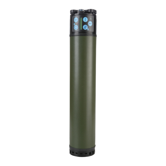
Saros 9400R-SEQ Operators & Service Manual (78 pages)
Brand:
Saros
| Category:
Medical Equipment
| Size: 10.71 MB
Table of Contents
Definition of Symbols Page / Warning Page
2
Table of Contents
4
Indications for Use
8
Indications
8
Contraindications
8
Safety Guidelines
8
Battery Safety
10
1 Introduction
11
General Information
11
Saros Oxygen System Specifications
12
Table 1-1. SAROS Specifications
12
Table 1-2. Pulse Mode Specifications
13
Table 1-3. Bolus Volume and Breath Rates
13
Table 1-4. Power Accessory Specifications
13
Table 1-5. Battery Specifications
13
Table 1-6. Independent Safety Testing
14
Table 1-7. SAROS
14
2 Introduction to Your Saros Oxygen System
15
Description of the Saros (9400-Seq) Assembly-Shippable
15
Figure 2-1. SAROS Components
15
Figure 2-2. SAROS Components
16
User Controls and System Status Indicators
17
Table 2-1. User Controls and Indicators
17
Recommended Operating Environments
19
Table 2-2. Recommended Operating Environments
19
3 Preparation for Use and Installation
20
Battery Installation Onto Saros
20
Locating the Saros
20
Saros Performance Verification Test
20
Figure 3-1. Battery Installation
20
4 Theory of Operation
21
Figure 4-1. System Board Diagram
22
Table 4-1. Battery Pack
24
5 Operating Instructions
26
Table 5-1. Typical New Battery Operating Time
27
Figure 5-1. Battery Installation
28
Table 5-2. Minimum Remaining Time on Battery
28
Operating the Saros for the First Time
29
Table 5-3. Pulse Settings
30
Table 5-4. Utility Menu Screens
31
6 Operator Maintenance & Service
32
Cleaning the Saros
32
Routine Maintenance
32
Table 6-1. Routine Maintenance
32
Cleaning or Replacing Air Inlet Filter
33
Figure 6-1. SAROS Components
33
Figure 6-2. Remove Cover
33
Replacing the Hepa Filter
34
Figure 6-3. Filter
34
Figure 6-4. Reinstall O2 Fitting/Hepa Filter
34
Run Device and Fully Drain Saros Battery
35
Saros Performance Verification Test
35
Replacing the 9V Battery
38
7 Alerts, Alarms, and Troubleshooting Table
38
Figure 6-5. Replacing 9V Battery
38
Table 7-1. Alarm Levels
38
System Troubleshooting Guide
39
Table 7-2. System Troubleshooting Guide
39
8 Reprogramming/Calibration
40
9 Shipping and Transporting the Saros
40
10 Storing and Discarding the Saros
40
Table 10-1. Storage Environment
40
11 Overhaul & Repair
41
Tools and Test Equipment
41
Maintenance and Service Parts
41
Table 11-1. Maintenance and Service Parts
41
Reprogramming after Overhaul and Repair Procedures
42
Saros Main Components
42
Figure 11-1. Inside SAROS
42
Alarm Indications and Codes
43
Table 11-2. Alarm Indications and Codes
43
Comprehensive Troubleshooting Guide
47
Table 11-3. Troubleshooting Guide
47
Removal Procedures
49
Battery Interface Plate, Rain Guard, and Sleeve
49
Figure 11-2. Removal of the Three BIP Screws
49
Figure 11-3. Removal of the Three Rain Guard Screws
49
Figure 11-4. Removal of the Rain Guard
49
Figure 11-5. Removal of Sleeve Alignment Ring
49
Inlet Cap Removal
50
Figure 11-6. Fiberglass Sleeve
50
Figure 11-7. Air Inlet Cover Removal
50
Figure 11-8. Filter Screen & 9V Removal
50
Figure 11-9. Inlet Cap Screw Removal
50
Figure 11-10. Oxygen Outlet Tube Disconnect
51
Figure 11-11. Front Panel Flex Cable Disconnect
51
Figure 11-12. Thermistor Connector and 9V Battery Connector
51
Figure 11-13. Inlet Cap Power
51
Figure 11-14. Tube Disconnect
52
Figure 11-15. Inlet Cap Removal
52
Figure 11-16. Detach Top Strut
52
Remove Pcb Assembly
53
Figure 11-17. Battery Power Wires for Battery Interface
53
Figure 11-18. Communication Connector for Battery Interface
53
Figure 11-19. ATF Thermistor Disconnect
53
Proportional Valve Removal (5293-Seq)
54
Figure 11-20. PCB Assembly
54
Figure 11-21. Proportional Valve Wire
54
Figure 11-22. Proportional Valve Tube
54
Figure 11-23. Replace Proportional Valve
54
Compressor Fan Removal (9767-Seq)
55
Figure 11-24. Remove Compressor Fan Wire
55
Figure 11-25. Lift the Proportional Valve
55
Figure 11-26. Compressor Fan
55
Battery Cable Removal (9201-Seq)
56
Figure 11-27. Hall Effect Sensor
56
Figure 11-28. Remove Wire Sleeve
56
Figure 11-29. Cable Ties and Rails
56
Rail Removal
57
Figure 11-30. Cable Ties and Struts
57
Figure 11-31. Left Strut
57
Figure 11-32. Right Strut
57
Atf & Compressor / Tank Assembly Removal
58
Figure 11-33. Kapton Tape
58
Figure 11-34. Exhaust Tube
58
Figure 11-35. Cable Ties
58
Figure 11-36. Silicone Tubing
58
Installation Procedures
59
General Procedure
59
Figure 11-37. ATF Ports
59
Figure 11-38. ATF Bulkhead
59
Figure 11-39. Thread Locking Procedure
59
Figure 11-40. Cable Tie Installation
59
Atf & Compressor/Product Tank Installation
60
Figure 11-41. ATF Bulkhead
60
Figure 11-42. Align
60
Figure 11-43. ATF Caps
60
Figure 11-44. down Pipe Hose
60
Figure 11-45. Cap
61
Figure 11-46. Cable Ties
61
Figure 11-47. Open SAROS
61
Rail Installation
62
Figure 11-48. Open SAROS
62
Figure 11-49. Right Strut
62
Figure 11-50. Route ATF Wires
62
Figure 11-51. Secure
62
Battery Cable Installation
63
Figure 11-52. Cable Tie Knots
63
Figure 11-53. Wire Sleeve
63
Figure 11-54. Secure Battery Wires
64
Figure 11-55. Slack
64
Figure 11-56. Secure ATF
64
Compressor Fan Replacement
65
Proportional Valve Replacement (5293-Seq)
65
Figure 11-57. Fan
65
Figure 11-58. Compressor Fan Wire
65
Figure 11-59. Proportional Valve
65
Installation of Pcb Assembly
66
Figure 11-60. Secure
66
Figure 11-61. Connect
66
Figure 11-62. Screws
66
Figure 11-63. Secure
67
Figure 11-64. Connect
67
Figure 11-65. Fan Connector
67
Figure 11-66. Flow Tube
68
Figure 11-67. Tighten
68
Figure 11-68. Tighten
68
Power Connector Replacement (9766-Seq)
69
Figure 11-69. Cable Ties
69
Figure 11-70. Top Strut
69
Figure 11-71. Remove Screws
69
Figure 11-72. Power Connector
69
Membrane Panel Replacement (9731-Seq)
70
Figure 11-73. Peel
70
Figure 11-74. Clean
70
Figure 11-75. Remove PSA Cover
70
Figure 11-76. Apply New User Panel
70
Inlet Cap Installation (Sp9756-Seq)
71
Figure 11-77. O-Ring Attached
71
Figure 11-78. Inlet Caps
71
Figure 11-79. Breach Tube
71
Figure 11-80. Power Harness Wires
71
Figure 11-81. Flex Cable
72
Figure 11-82. Ambient Air Thermistor
72
Figure 11-83. Oxygen Outlet Tube
72
Figure 11-84. Inlet Cap Mounting Screws
72
Installation of the Sleeve & Battery Interface Plate
73
Figure 11-85. 9V Battery
73
Figure 11-86. Align Covers and Tighten
73
Figure 11-87. Slide Sleeves
73
Figure 11-88. Second Sleeve
73
Figure 11-89. Battery Interface Assembly
74
Figure 11-90. Attach
74
Figure 11-91. Align
74
12 Service Records & Retention
75
Record Hours of Operation and Software Version
75
Table 12-1. Log the Results
75
Service and Maintenance Record
76
Table 12-2. Sample SAROS Maintenance Record
76
APPENDIX A A-1. SAROS Performance Verification Checklist
77
Advertisement
Advertisement
Related Products
Saros 4000
Saros Categories
Medical Equipment
Speakers
More Saros Manuals
Login
Sign In
OR
Sign in with Facebook
Sign in with Google
Upload manual
Upload from disk
Upload from URL