Sign In
Upload
Manuals
Brands
Princeton Instruments Manuals
Security Camera
ProEM+ EMCCD
Princeton Instruments ProEM+ EMCCD Manuals
Manuals and User Guides for Princeton Instruments ProEM+ EMCCD. We have
1
Princeton Instruments ProEM+ EMCCD manual available for free PDF download: User Manual
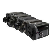
Princeton Instruments ProEM+ EMCCD User Manual (152 pages)
EMCCD Cameras For Imaging and Spectroscopy
Brand:
Princeton Instruments
| Category:
Security Camera
| Size: 6 MB
Table of Contents
Table of Contents
4
Chapter 1 Introduction
12
Proem + Cameras
12
EMCCD Technology and On-Chip Multiplication Gain
12
Integrated Controller
13
Grounding and Safety
13
Figure 1. Comparison of Proem+ Frame Transfer, Kinetics, and Full Frame EMCCD Array Structures
13
Precautions
14
UV Coating
14
Cleaning
14
Camera
14
Optical Surfaces
14
Repairs
15
About this Manual
15
Manual Organization
15
Safety Related Symbols Used in this Manual
16
Chapter 2 System Component Descriptions
18
System Components
18
Standard Components
18
Optional System Components
18
Figure 2. Typical Proem+ System Components
18
Proem+ Camera
19
Coolant Circulator
21
Cables
21
Hoses
21
Certificate of Performance
21
User Manuals
22
Optional Components
22
Application Software
22
Coolcube II Circulator
23
C- to Spectroscopy-Mount Adapter
23
Adjustable C- to Spectroscopy-Mount Adapter
23
Chapter 3 Installation Overview
24
Figure 3. Typical Imaging Experiment Layout with Air-Cooled Camera
25
Figure 4. Typical Spectroscopy Experiment Layout with Air-Cooled Camera
25
Figure 5. Typical Spectroscopy Experiment Layout with Air-Cooled Camera and Isoplane
26
Figure 6. Typical Imaging Experiment Layout with Air/Liquid-Cooled Camera
26
Figure 7. Typical Spectroscopy Experiment Layout with Air/Liquid-Cooled Camera
27
Chapter 4 System Setup
28
Introduction
28
Unpacking the System
28
Checking the Equipment and Parts Inventory
29
System Requirements
29
Environmental Requirements
29
Ventilation
29
Power
29
Host Computer
30
Attaching a Lens to a C-Mount Adapter
31
Mounting the Lens
31
Adjusting the C-Mount Adapter
31
Figure 8. Adjustable C-Mount Adapter
31
Mounting the Adjustable C- to Spectroscopy-Mount Adapter
32
Figure 9. Adjustable C- to Spectroscopy-Mount Adapter
33
Positioning the Proem+:512Bk Masks
34
Opening/Closing Proem+:1600 Manual Shutter
34
Figure 10. Front View of Proem+:512Bk Camera
34
Figure 11. Front View of Proem+:1600 Camera
34
Making the Camera-Circulator Connections for a Coolcube
35
Software Installation
36
Winx
36
Lightfield
36
Figure 12. Winx Installation Select Installation Type Dialog
36
Entering the Default Camera System Parameters
37
Winx
37
Figure 13. Lightfield Installation Wizard Dialog
37
Figure 14. Camera Detection Wizard - Welcome Dialog
37
Lightfield
38
Figure 15. Lightfield Experiment Workspace
38
Chapter 5 Operation
40
Introduction
40
Figure 16. Block Diagram of Proem+ System
40
Winx First Light Instructions
41
Imaging
41
Figure 17. Controller/Camera Tab
42
Figure 18. Detector Temperature Dialog (512B on Left, 1024B on Right)
43
Figure 19. Experiment Setup|Timing Tab
43
Spectroscopy
44
Figure 20. Controller/Camera Tab
46
Figure 21. Detector Temperature Dialog for a 1600 Series Camera
46
Figure 22. Experiment Setup|Timing Tab
47
Lightfield First Light Instructions
52
Imaging
52
Figure 23. Available Devices Area
53
Figure 24. Experiment Devices Area
53
Figure 25. View Area
54
Figure 26. View Area Displaying an Image
55
Spectroscopy
56
Figure 27. Available Devices Area
57
Figure 28. Experiment Devices Area
57
Figure 29. View Area
59
Figure 30. Spectrometer Alignment: before Rotational Alignment
60
Figure 31. Spectrometer Alignment: after Rotational Alignment
61
Exposure and Signal
63
Exposure Time
63
Avalanche Gain {EM Gain
63
EM Gain Calibration
64
CCD Temperature
65
Dark Charge
65
Bias Active Stabilization Engine (BASE™)
65
Clock Induced Charge (CIC)
66
Saturation
66
Table 1. Major Differences between Dark Current and Clock-Induced Charge
66
Cleaning
67
Figure 32. Clean Cycles Timing Diagram
67
Readout
68
Introduction
68
Dual-Readout Port Operation
69
Figure 33. EMCCD Array Structure
69
Controller Gain {Analog Gain
70
Readout Rate
70
Table 2. Typical Controller Gains
70
Table 3. Proem+ Readout Rates
70
Region of Interest
71
Binning
72
Exposure - Readout Modes
72
Figure 34. Binning and Array Orientation
72
Figure 35. Timing Diagram for Frame Transfer Mode When Exposure Time < Readout Time
73
Figure 36. Timing Diagram for Frame Transfer Mode When Exposure Time > Readout Time
74
Figure 37. Timing Diagram for Full Frame Mode
75
Readout Time
76
Figure 38. Full Frame at Full Resolution
76
Chapter 6 Advanced Topics
78
Introduction
78
Frame Transfer/Full Frame Timing {Trigger Response} Modes and Shutter Control {Shutter Mode
79
Overview
79
EXT SYNC Trigger Input
79
Free Run {No Response
79
Figure 39. Rear of Proem+ Camera
79
External Sync {Readout Per Trigger
80
Figure 40. Free Run Timing Diagram
80
Figure 41. External Sync Timing Diagram
80
External Sync with Continuous Cleans {Clean until Trigger} Timing
81
Figure 42. Continuous Cleans {Clean until Trigger} Flowchart
81
Bulb Trigger {Expose During Trigger Pulse} Timing
82
Figure 43. Winx Continuous Cleans Timing Diagram
82
Figure 44. Lightfield Clean until Trigger (CUT) Timing Diagram
82
Trigger Start {Start on Single Trigger
83
Fast and Safe Modes
83
Introduction
83
Fast Mode (Winx and Lightfield)
83
Figure 45. Bulb Trigger {Expose During Trigger Pulse} Timing Diagram: Non-Overlap
83
Safe Mode (Winx)
84
Figure 46. Flowcharts of Safe and Fast Mode Operation
85
LOGIC out Control
86
Kinetics Mode
87
Introduction
87
Figure 47. Comparison of READ OUT, SHUTTER, and ACQUIRING Logic out Levels
87
Figure 48. Sensor Expander: Kinetics Readout Mode
87
Figure 49. Hardware Setup Dialog: Kinetics Readout Mode
87
Kinetics Readout
88
Figure 50. Two Examples Illustrating Partial Illumination of CCD for Kinetics Mode in
88
Figure 51. Kinetics Data Acquired Based on Masked Images Shown in Figure 50
89
Kinetics Timing Modes and Shutter Control
90
Triggered Operation
90
Figure 52. Experiment Setup| Timing Tab
90
Cleaning the CCD
91
Figure 53. Shutter and Trigger Expanders
91
Figure 54. Example Showing Kinetics Operation Using Single Trigger {Readout Per Trigger
91
Figure 55. Example Showing Kinetics Operation Using Multiple Trigger {Shift Per Trigger
91
Setting up a Kinetics Experiment
92
Figure 56. Typical Kinetics Experiment Layout
92
Summary
94
Spectra-Kinetics (Option)
94
Table 4. Comparison of Kinetics and Spectra-Kinetics for Proem+:512B/Bk and Proem+:1024B
94
Figure 57. Proem+:512Bk EMCCD
95
Figure 58. Example of Masking for Spectra-Kinetics: 20 Rows Exposed
95
Summary
96
Custom Modes
96
Introduction
96
Custom Chip {Custom Sensor
96
Figure 59. Comparison of Standard ROI and Custom Chip Readout Rates
97
Figure 60. Winx: Custom Chip Tab
97
Custom Timing
98
Figure 61. Lightfield: Custom Sensor Pane
98
Figure 62. Lightfield: Custom Timing
98
Figure 63. Winx: Vertical Shift
99
Chapter 7 Tips
100
Counter the Effects of Aging
100
Maximize Throughput by Choosing the Right Vacuum Window Coating
100
Reduce Spectral Readout Time by Using the Custom Chip/Timing {Custom Sensor} Feature
101
Introduction
101
Approximation of Spectral Readout Time
101
Figure 64. Vacuum Window Transmission Data
101
Winx Step-By-Step Procedure
102
Lightfield High Speed Proem Add-In
104
Figure 65. High Speed Proem Settings
104
Lightfield Step-By-Step Procedure
105
Figure 66. Lightfield Settings
107
Chapter 8 Troubleshooting
108
Introduction
108
Acquisition Started but Data Display Is Empty
109
Figure 67. Acquisition Display and Invalid ROI
109
Acquisition Started but Viewer Contents Do Not Update
110
Baseline Signal Suddenly Changes
110
Figure 68. Acquisition Display
110
Camera Not Found
111
Camera Stops Working
111
Figure 69. Camera Not Found Dialog
111
Camera1 (or Similar Name) in Camera Name Field
112
Figure 70. Camera1 in Camera Name Field
112
Cooling Troubleshooting
113
Temperature Lock Cannot be Achieved or Maintained
113
Gradual Deterioration of Cooling Capability
113
Data Overrun Due to Hardware Conflict Message
114
Device Is Not Found
114
Figure 71. Data Overrun Due to Hardware Conflict Dialog
114
Figure 72. Devices Missing Dialog
114
Device Is Occupied
115
Ethernet Network Is Not Accessible
115
For Winx
115
Figure 72. Occupied Device Icon
115
For Lightfield
116
Figure 74. Ebus Driver Installation Tool Dialog
116
Figure 75. Ebus Driver Installation Tool Dialog
116
Program Error Message
117
Figure 76. Program Error Dialog
117
Serial Violations Have Occurred. Check Interface Cable
118
Smeared Images
118
TEC Fault LED Comes on
118
Figure 77. Serial Violations Have Occurred Dialog
118
TEC Fault LED Comes
118
Winx or Lightfield Crashes When Adding Gige Camera to System
119
Figure 78. Windows Start Button
119
Figure 79. Device Manager Dialog
119
Figure 80. Right-Click Menu
119
Figure 81. Settings Tab
120
Figure 82. System Settings Change Dialog
120
Appendix A Basic Specifications
122
Window
122
CCD Arrays
122
Mounts
123
Focal Distance (Optical)
123
Camera
123
Table 5. Default Operating Temperature
123
Options
124
Appendix B Outline Drawings
126
Proem+ Camera: Standard C-Mount
126
Figure 83. Proem+:512B/1024B Outline Drawing
126
Proem+:512Bk - Kinetics
127
Figure 84. Proem+:512Bk Outline Drawing
127
Proem+:1600 and 1600 - Full Frame, Spectroscopy
128
Figure 85. Proem+:1600 Series Flange-Mount Camera Outline Drawing
128
Proem+ Power Supply
129
Figure 86. Proem+ Power Supply Outline Drawing
129
Coolcube II (Optional)
130
Figure 87. Coolcube
130
Appendix C Mounting the Proem+ to a Spectrograph
132
Introduction
132
Acton and Proem+:1600 Series with 3.60" Flange-Mount
133
Isoplane and Proem+ with 3.60" Flange Mount
134
Acton and Proem+ with C- to Spectroscopy-Mount Adapter
135
Acton and Proem+ with Adjustable C- to Spectroscopy-Mount Adapter (7050-0104 for SP2350/SP-2550)
136
Acton and Proem+ with Adjustable C- to Spectroscopy-Mount Adapter (7050-0107 for SP2150/SP-2750)
137
Appendix D Cross-Referencing of Winx and Lightfield Terms
138
Winx-To-Lightfield
138
Lightfield-To-Winx
140
Declaration of Conformity
142
Warranty & Service
144
Limited Warranty
144
Basic Limited One (1) Year Warranty
144
Limited One (1) Year Warranty on Refurbished or Discontinued Products
144
XP Vacuum Chamber Limited Lifetime Warranty
144
Sealed Chamber Integrity Limited 12 Month Warranty
144
Vacuum Integrity Limited 12 Month Warranty
145
Image Intensifier Detector Limited One Year Warranty
145
X-Ray Detector Limited One Year Warranty
145
Software Limited Warranty
145
Owner's Manual and Troubleshooting
145
Your Responsibility
146
Contact Information
147
Index
148
Advertisement
Advertisement
Related Products
Princeton Instruments ProEM+:512B
Princeton Instruments ProEM+:512BK
Princeton Instruments ProEM+:1024B
Princeton Instruments PI-MAX System
Princeton Instruments PI-MAX2 System
Princeton Instruments PI-MAX4
Princeton Instruments PhotonMAX System
Princeton Instruments Roper Scientific PG-200
Princeton Instruments PIXIS System
Princeton Instruments PI-MAX 3 System
Princeton Instruments Categories
Security Camera
Digital Camera
Measuring Instruments
Lighting Equipment
Controller
More Princeton Instruments Manuals
Login
Sign In
OR
Sign in with Facebook
Sign in with Google
Upload manual
Upload from disk
Upload from URL