Sign In
Upload
Manuals
Brands
Princeton Instruments Manuals
Security Camera
PI-MAX4
Princeton Instruments PI-MAX4 Manuals
Manuals and User Guides for Princeton Instruments PI-MAX4. We have
1
Princeton Instruments PI-MAX4 manual available for free PDF download: Manual
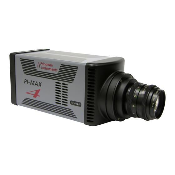
Princeton Instruments PI-MAX4 Manual (326 pages)
Camera System
Brand:
Princeton Instruments
| Category:
Security Camera
| Size: 14 MB
Table of Contents
Table of Contents
5
List of Figures
12
List of Tables
17
Chapter 1: Introduction
19
PI-MAX4 System Components
19
Figure 1-1: Typical PI-MAX4 System Components
19
Summary of PI-MAX4 Data Acquisition
21
Figure 1-2: Major Components of the Intensifier-CCD
21
Safety Related Symbols Used in this Manual
22
Grounding and Safety
23
Intensifier Modes and Safety
24
Audible Alarm
24
High Intensity Light Damage
25
Precautions
25
Cleaning and Maintenance
26
Cleaning Optical Surfaces - Protective Window
26
Flushing and Refilling the CCD Chamber
26
Repairs
26
About this Manual
27
Conventions Used in this Manual
27
Manual Organization
27
Chapter 2: System Installation
29
Table 2-1: PI-MAX4 System Installation Procedure
29
System Configuration Diagrams
31
Figure 2-1: Typical PI-MAX4 System Diagram
31
Figure 2-2: Typical PI-MAX4: 1024I-RF System Diagram
31
Chapter 3: System Setup
33
Dangers and Warnings
33
Unpacking the System
33
Checking the Equipment and Parts Inventory
34
General System Requirements and Information
35
Ventilation
35
Power Specifications
35
Host Computer Specifications
36
Winx Host Computer Requirements
36
Lightfield Host Computer Requirements
37
Mounting the Camera
38
Imaging Applications
38
Spectroscopy Applications
39
Application Software Installation
39
Winx Applications
39
Figure 3-1: Typical Winview/32 Setup Dialog
40
Lightfield Applications
41
Figure 3-2: Typical Lightfield Installshield Wizard Dialog
41
Connect the Circulator [Liquid-Cooled Cameras Only]
42
Circulator
42
Configure Default Camera System Parameters
44
Winx (Versions 2.5.25.X or Higher)
44
Typical Winx Camera Detection Wizard Dialog
44
Lightfield
45
PI-MAX ® 4 System Manual Issue
46
Chapter 4 First Light
47
Required Equipment and Cables
47
Cable Connections
47
Before Turning on the System
48
Turning on the System
48
Lightfield First Light Instructions
49
Assumptions
49
Getting Started
49
Parameter Configuration
50
Figure 4-1: Lightfield Desktop: Available Devices
50
Figure 4-2: Camera Icon in Experiment Devices Area
51
Acquiring Data
52
Figure 4-3: Lightfield Desktop View Area
52
Figure 4-4: Typical Supersynchro Timing Expander
53
Table 4-1: Configuration Parameters by Mode
53
Focusing
54
Figure 4-5: Lightfield View Area Displaying an Acquired Image
54
Winx First Light Instructions
55
Assumptions
55
Getting Started
55
Configuring the Software
55
Figure 4-6: Typical Winx Pulsers Dialog
55
Figure 4-7: Typical Supersynchro Dialog: Trigger in Tab
56
Figure 4-8: Typical Supersynchro Dialog: Gating Tab
56
Figure 4-9: Typical Repetitive Gating Setup Dialog
57
Figure 4-10: Typical Experiment Setup Dialog: Main Tab
58
Figure 4-11: Typical Experiment Setup Dialog: ADC Tab
58
Initial Data Acquisition
59
Figure 4-12: Typical Experiment Setup Dialog: ROI Setup Tab
59
Focusing
60
Figure 4-13: Sample Acquired Test Image
60
Chapter 5 Gate Mode Operation
61
Data Acquisition Sequence
61
Winx System On/Off Sequences
62
Figure 5-1: Block Diagram: Signal Path in a Standard PI-MAX4 System
62
Pre-Exposure Removal of Accumulated Charge
63
Dark Charge
63
Cleaning
64
Figure 5-2: Clean Cycles in Internal Trigger Mode of Operation
64
Phosphor Decay Delay
65
Temperature Control
66
Cooling Method
66
Figure 5-3: Winx: Phosphor Decay Delay
66
Figure 5-4: Lightfield: Phosphor Decay Delay Parameters
66
Necessary Cooling Precautions
67
Setting the Temperature
67
Exposure
68
Exposure with an Image Intensifier
68
Exposure Timing
68
Saturation
69
Background Subtraction
69
Readout of the Array
70
Interline CCD Readout
71
Figure 5-5: Interline CCD Readout
71
Figure 5-6: Step 1: Non-Overlapped, Early Exposure
72
Figure 5-7: Step 2: Non-Overlapped, Early Readout
72
Figure 5-8: Step 3: Non-Overlapped, Transfer to Output Node
73
Figure 5-9: Step 4: Non-Overlapped, End of Readout
73
Full-Frame CCD Readout
74
Figure 5-10: Full Frame CCD Readout
74
Binned Readout (Hardware Binning)
76
CCD Type and Readout Port(S)
77
Figure 5-11: Dual Port Readout: 2 × 2 Binning of Interline CCD
77
Figure 5-12: Dual Port Readout: Lightfield Setting, 2X2 Binning, Interline CCD
78
Figure 5-13: Single Port Readout: 2 × 2 Binning of Full Frame CCD
78
Figure 5-14: Experiment Setup: ROI Configuration Dialog
79
Lightfield and Partial Frame ROI Binning
80
Figure 5-15: Typical Edit Regions of Interest Window
80
Figure 5-16: Single Port Readout: Partial Frame, 2×2 Binning, Interline CCD
81
Software Binning
82
Figure 5-17: Dual Port Readout: Lightfield Settings, 5×3 Binning, Interline CCD
82
Controller Gain {Analog Gain
83
Digitization
83
Logic out Control
84
Figure 5-18: Typical PI-MAX4 Hardware Setup Dialog
84
Figure 5-19: Timing Diagram: Shutter {Shutter Open}, Read out {Reading out
84
Winx Experiment Setup
86
Main Tab
86
Figure 5-20: Typical Experiment Setup Dialog: Main Tab
86
Timing Tab
87
Figure 5-21: Typical Experiment Setup Dialog: Timing Tab
87
Figure 5-22: Fast Mode/Slow Mode Flow Charts
88
Lightfield Experiment Setup
90
Common Acquisition Settings Expander
90
Figure 5-23: Typical Common Acquisition Settings Expander
90
Figure 5-24: Typical Advanced Intensifier Dialog
91
Region of Interest Expander
92
Figure 5-25: Typical Region of Interest Expander
92
Trigger Expander
93
Figure 5-26: Typical Trigger Expander: Internal Trigger Source Parameters
93
Figure 5-27: Typical Trigger Expander: External Trigger Source Parameters
93
Supersynchro Timing Expander
94
Figure 5-28: Supersynchro Timing Expander
94
Chapter 6: Lightfield and Gated Operation
97
Gating
97
Safety Precautions
98
Intensifier Mode
98
Alarms
98
Timing Mode
99
Table 6-1: Internal Sync Information for Gated Operation
99
Micro-Channel Plate (MCP) Bracket Pulsing
100
Figure 6-1: Timing Diagram: MCP Bracket Pulsing
100
Bracket Pulsing in LIF Measurements
101
Bracket Pulsing in Nanosecond Pump Probe Experiments
101
Limitations of Bracket Pulse Gating
101
Impact of Bracket Pulsing on Delay
102
Configuration
103
Figure 6-2: Timing Diagram: MCP Bracket Pulsing
103
Experiments
104
Figure 6-3: Typical PI-MAX4 Experiments
104
Swept Gate Experiment [Fixed Width, Variable Delay]
105
Experiment Supplies the Master Clock
105
Figure 6-4: Block/Timing Diagram: Swept Gate Experiment
106
Figure 6-5: Typical Sensor Expander
106
Figure 6-6: Typical Sensor Cleaning Dialog
107
Figure 6-7: Typical Reset to Default
107
Figure 6-8: Typical Spectrometer Expanders
108
Figure 6-9: Typical Regions of Interest Expander: Full Sensor
109
Figure 6-10: Typical Common Acquisition Settings Expander
110
Figure 6-11: Typical Analog to Digital Conversion Expander
110
Figure 6-12: Typical Trigger Expander
111
Figure 6-13: Typical Regions of Interest Expander: Full Sensor Binned
112
Figure 6-14: Trigger Expander: External Trigger Source Configuration
113
Figure 6-15: Typical Supersynchro Timing Expander
114
Figure 6-16: Typical Supersynchro Timing: Syncmaster on
115
Figure 6-17: Typical Experiment Results: Frame Cross Section
116
Syncmaster1 Supplies the Master Clock
117
Figure 6-18: Block Diagram: Syncmaster1 as Master Clock
117
Figure 6-19: Timing Diagram: Syncmaster1 as Master Clock
117
Single Shot Experiment
118
Figure 6-20: Block Diagram: Single Shot Experiment
118
Table 6-2: Single Shot Experiment Time Budget
118
Figure 6-21: Cleaning Cycles, Cleaning and Skipping Expander
119
Figure 6-22: Common Acquisition Settings Expander: Intensifier Gain
120
Figure 6-23: Typical Repetitive Gating Setup: 100 Ns Width, 25 Ns Delay
121
Figure 6-24: Single Shot Result: Fluorescence Spot, Width = 100 Ns
122
Figure 6-25: Single Shot Result: Fluorescence Spot, Width = 100 Ns
123
Swept Gate Experiment [Variable Width, Variable Delay]
124
Static Gate Experiment [Fixed Width, Fixed Delay]
124
Figure 6-26: Repetitive Gating Setup Dialog
124
Chapter 7: Winx and Gated Operation
125
Gating
125
Safety Precautions
126
Intensifier Mode
126
Alarms
127
Timing Mode
127
Micro-Channel Plate (MCP) Bracket Pulsing
128
Table 7-1: Internal Sync Information for Gated Operation
128
Bracket Pulsing in LIF Measurements
129
Figure 7-1: Timing Diagram: MCP Bracket Pulsing
129
Bracket Pulsing in Nanosecond Pump Probe Experiments
130
Limitations of Bracket Pulse Gating
130
Impact of Bracket Pulsing on Delay
131
Configuration
131
Figure 7-2: Timing Diagram: MCP Bracket Pulsing
131
Experiments
132
Figure 7-3: Typical PI-MAX4 Experiments
132
Swept Gate Experiment [Fixed Width, Variable Delay]
133
Experiment Supplies the Master Clock
133
Figure 7-4: Block/Timing Diagram: Swept Gate Experiment
134
Figure 7-5: Typical Hardware Setup Dialog
135
Figure 7-6: Typical Winspec/32 Installation Sequence: Acton 300I
136
Spectrograph
136
Figure 7-7: Typical Move Spectrograph Dialog
137
Figure 7-8: Typical Experiment Setup Dialog: Main Tab
137
Figure 7-9: Typical Experiment Setup Dialog: Timing Tab
138
Figure 7-10: Typical Experiment Setup Dialog: ADC Tab
139
Figure 7-11: Typical Experiment Setup Dialog: ROI Tab
139
Figure 7-12: Typical Winx Pulsers Dialog
140
Figure 7-13: Typical Supersynchro Dialog: Trigger in Tab
140
Figure 7-14: Typical Winx Pulsers Dialog
141
Figure 7-15: Typical Supersynchro Dialog: Trigger in Tab
141
Figure 7-16: Typical Supersynchro Dialog: Gating Tab
142
Figure 7-17: Typical Sequential Gating Setup Dialog
142
Figure 7-18: Typical View Width/Delay Sequence Dialog
143
Figure 7-19: Typical Supersynchro Dialog: Trigger out Tab
144
Figure 7-20: Experiment Setup: Timing Tab
145
Figure 7-21: Experiment Setup: Main Tab
145
Figure 7-22: Typical Experiment Results Shown in 3-D
146
Figure 7-23: Block Diagram: Syncmaster1 as Master Clock
147
Figure 7-24: Timing Diagram: Syncmaster1 as Master Clock
147
Syncmaster1 Supplies the Master Clock
147
Figure 7-25: Block Diagram: Single Shot Experiment
148
PI-MAX ® 4 System Manual Issue
148
Single Shot Experiment
148
Table 7-2: Single Shot Experiment Time Budget
148
Figure 7-26: Hardware Setup Dialog: Cleans/Skips Tab
149
Figure 7-27: Experiment Setup Dialog: Main Tab
150
Figure 7-28: Typical Repetitive Gating Setup Dialog
150
Figure 7-29: Single Shot Result: Fluorescence Spot, Width = 100 Ns
151
Figure 7-30: Single Shot Result: Fluorescence Spot, Width = 100 Ns
151
Swept Gate Experiment [Variable Width, Variable Delay]
152
Static Gate Experiment [Fixed Width, Fixed Delay]
152
Figure 7-31: Repetitive Gating Setup Dialog
152
Chapter 8: Timing Generator
153
Pulse Set
153
Figure 8-1: Timing Diagram: Pulse Set
153
Supported Timing Generator Trigger Modes
154
Figure 8-2: Timing Diagram: Trigger Per Pulse
154
Figure 8-3: Timing Diagrams: Three Repetition Sequence
154
Single Sequence
154
Figure 8-4: Timing Diagram: 3 Repetition Sequence, Trigger Per Pulse
155
Supported Timing Generator Trigger Modes
155
Time Stamping
155
Chapter 9: Lightfield and Dual Image Feature
157
Requirements
157
Figure 9-1: Readout Expander
157
Interline CCD Operation
158
Figure 9-2: Common Acquisition Settings Expander
158
Trigger Setup
159
Trigger Response
159
Figure 9-3: Trigger Expander: Internal Trigger Source
159
Figure 9-4: Timing Diagram: Single-Trigger (Readout Per Trigger) DIF
159
Trigger Source
160
Internal Trigger Source
160
Figure 9-5: Timing Diagram: Dual-Trigger (Shift Per Trigger) DIF
160
Figure 9-6: Supersynchro Timing Expander: DIF Operation
160
External Trigger Source
161
Figure 9-7: Trigger Expander: External Trigger Source
161
Using Pre-Trigger
162
Figure 9-8: Trigger Expander
163
Figure 9-9: Timing Diagram: Pre-Trigger, Single Trigger (Readout Per Trigger)
163
Figure 9-10: Timing Diagram: Pre-Trigger, Dual Trigger (Shiftper Trigger)
164
Figure 9-11: Timing Diagram: Pre-Trigger with Slightly Late Input Trigger
164
Figure 9-12: Timing Diagram: Pre-Trigger with very Late Input Trigger
165
Configure a Single-Trigger DIF Acquisition
166
Figure 9-13: Block Diagram: Single-Trigger DIF Acquisition
166
Figure 9-14: Timing Diagram: Single-Trigger DIF Acquisition
166
Configure a Dual-Trigger DIF Acquisition
168
Figure 9-15: Block Diagram: Dual-Trigger DIF Acquisition
168
Figure 9-16: Timing Diagram: Dual-Trigger DIF Acquisition
169
Tips and Tricks
171
Chapter 10: Winx and Dual Image Feature
173
Requirements
173
Interline CCD Operation
173
Timing Modes
174
Configure a Single Trigger DIF Experiment
174
Hardware
174
Software
174
Figure 10-1: Block Diagram: DIF Experiment
174
Operation
175
Figure 10-2: Timing Diagram: DIF Operation, Single Trigger
175
Figure 10-3: Winx Hardware Setup Dialog: Controller/Camera Tab
176
Figure 10-4: Winx Experiment Setup Dialog: Main Tab
176
Figure 10-5: Winx Experiment Setup Dialog: Timing Tab
177
Figure 10-6: Winx Pulsers Dialog
177
Figure 10-7: Winx Supersynchro Dialog: Gating Tab
178
Figure 10-8: Winx DIF Gating Setup Dialog
178
Figure 10-9: Winx Supersynchro Dialog: Trigger in Tab
179
Figure 10-10:Winx Supersynchro Dialog: Trigger out Tab
179
Configure a Dual Trigger DIF Experiment
180
Hardware
180
Software
180
Operation
180
Figure 10-11:Block Diagram: DIF Experiment
180
Figure 10-12:Timing Diagram: DIF Operation, Dual Trigger
181
Figure 10-13:Winx Hardware Setup Dialog: Controller/Camera Tab
181
Figure 10-14:Winx Experiment Setup Dialog: Main Tab
182
Figure 10-15:Winx Experiment Setup Dialog: Timing Tab
183
Figure 10-16:Winx Pulsers Dialog
183
Figure 10-17:Winx Supersynchro Dialog: Gating Tab
184
Figure 10-18:Winx DIF Gating Setup Dialog: Dual Trigger
184
Figure 10-19:Winx Supersynchro Dialog: Trigger in Tab
185
Figure 10-20:Winx Supersynchro Dialog: Trigger out Tab
185
Tips and Tricks
186
Chapter 11: MCP Gating Option
187
Figure 11-1: Timing Diagram: Normal Gated Operation
187
Figure 11-2: Timing Diagram: MCP Bracket Pulsing Operation
187
Setup and Operation
188
Figure 11-3: Timing Diagram: MCP Gated Operation for Gen II Intensifiers
188
Figure 11-4: QE Curves: Gen II Intensifiers
188
Gain Variation
189
Fluorescence Experiment
189
Cabling for MCP Gated Operation
189
Figure 11-5: Block Diagram: MCP Gated Operation Cabling
189
Figure 11-6: Timing Diagram: MCP Gated Operation
190
Chapter 12: Picosecond Gating Option
191
Activating Picosecond Operation
191
Gain and Gate Width
191
MONITOR Operation
192
Repetition Rate Issues
192
Table 12-1: Typical Picosecond Gating Information: PI-Max4:1024I
192
Timing
193
Methods for Finding a Short Optical Pulse
193
Chapter 13: PI-MAX4: 1024I-RF and RF Modulation
195
Basics of RF Modulation on Intensified Ccds
195
Advantages of PI-MAX4: 1024I-RF
196
Figure 13-1: System Diagram: RF Operation
196
RF Experiment Design in Lightfield
197
Requirements
197
Trigger Response
197
Gating Mode
198
Repetitive
198
Figure 13-2: Sypersynchro Timing: RF Mode Options
198
Sequential
200
Custom
202
Figure 13-3: Typical Edit Custom Phase Modulations Window
204
Figure 13-4: Add a Single Modulation Phase
204
Figure 13-5: Add Phase Sweep
206
Table 13-1: Phase Sweep Information for Sweep > 360
206
Figure 13-6: Typical Modulation Phase Curve
207
Figure 13-7: Typical Modulation Phase Curve with Points Shuffled
208
Phase Modulation Sorting Add-In
209
Figure 13-8: Typical Manage Add-Ins Dialog
209
Figure 13-9: Typical Phase Modulation Sorting Add-In
210
Figure 13-10:Typical Phase Modulation Sorting Add-In Button: Data Toolbar
210
Figure 13-11:Typical Sort Phases Dialog
211
Figure 13-12:Typical Sort Phases Dialog: SPE File Specified
211
PI-MAX4: 1024I-RF Rear Panel Information
212
Figure 13-13:PI-MAX4: 1024I-RF Rear Panel
212
Table 13-2: PI-MAX4: 1024I-RF Connectors, Indicators, and Switches
213
PI-MAX4: 1024I-RF Power Supply Rear Panel Information
214
Figure 13-14:PI-MAX4: 1024I-RF Power Supply Rear Panel
214
RF Modulator Specifications
215
Table 13-3: PI-MAX4: 1024I-RF Power Supply Connectors, Indicators
215
Chapter 14: PI-MAX4: EM Family
217
Electron Multiplication
217
Figure 14-1: Block Diagram: EMCCD with Dual Output Registers
218
Enabling EM
219
Figure 14-2: Typical Emiccd Hardware Stackup
219
Figure 14-3: Enabling Electron Multiplication
219
Emiccd Gain Mode
220
Figure 14-4: Typical Emiccd Gain Configuration Field
220
Optimal
221
Manual
221
Figure 14-5: Typical Emiccd Gain Configuration: Optimal Mode
221
Figure 14-6: Typical Intensifier Gain Configuration: Manual Mode
221
Figure 14-7: Typical EM Gain Configuration Parameters: Manual Mode
222
Figure 14-8: Typical EM Gain Configuration Display for EM Gain > 100
223
Kinetics
224
Masking
224
Figure 14-9: Configuring Readout Mode
224
Figure 14-10:Typical Full-Frame and Frame Transfer Ccds, Kinetics Masking
225
Table 14-1: Mask/Window Sizes for 16 X 16 CCD, Full Frame
225
Trigger Sources
226
Image/Frame Acquisition
226
Figure 14-11:Timing Diagrams: Kinetics Exposure-Shift
227
Data Readout
228
Binning
228
Figure 14-12: Timing Diagram: Kinetics Readout and Data Storage
229
Figure 14-13: Timing Diagram: Kinetics Readout and Data Storage
230
Figure 14-14:File Storage Convention
231
File Storage Conventions
231
Configuring Kinetics
232
Figure 14-15:Configuring Readout Mode
232
Cleaning the CCD
233
Figure 14-16:Configuring Trigger Response
233
Configuring a Kinetics Experiment
234
Figure 14-17:Block Diagram: Typical Kinetics Experiment
234
Configuring the Software Parameters
235
Photon Detection
236
Configuring Photon Detection
237
Figure 14-18:Typical Online Processes Expander: Photon Detection
237
Figure 14-19:Typical Thresholding and Clipping Configuration Parameters
237
Figure 14-20:Typical High Speed Camera Expander
238
High Speed Camera Add-In
238
Figure 14-21:Typical High Speed Camera Spectroscopy Settings
239
Figure 14-22:Typical High Speed Camera Imaging Settings
239
Figure 14-23:Typical Previous and Current Frame Rate Information
239
Figure 14-24:Typical Configuration Options: Time Stamping, Frame Tracking
240
Configuring the High Speed Camera
239
Chapter 15: Tips and Tricks
241
Overexposure Protection
241
Signal Delay
242
Time Budgets
242
Measuring Coincidence
243
Adjusting the Signal Delay
244
Optimizing the Gate Width and Delay
244
Lasers
245
Free Running Lasers
245
Triggered Lasers
245
Lens Performance
246
Throughput
246
Depth of Field
246
Jitter
246
Inhibiting the Pulser During Readout
246
PI-MAX ® 4 System Manual Issue
246
Baseline Signal
247
Temperature Lock
247
Intensifier Alarm
247
Chapter 16: Component Descriptions
249
Mount Adapters
249
Switches, Connectors, and Indicators
250
Figure 16-1: PI-MAX4 Rear Panel
250
Figure 16-2: PI-MAX4: 1024I-RF Rear Panel
250
Aux I/O
251
AUX out
251
AUX Power [PI-MAX4: 1024I-RF Only]
251
Coolant Ports
251
Error LED
252
Fan
252
Gig-E
252
PWR On/Off Switch
252
Logic out
253
Mon RF out [PI-MAX4: 1024I-RF Only]
253
Monitor
253
Power Connector
253
Ready out
253
Thermoelectric Cooler
254
Trigger in
254
User RF out [PI-MAX4: 1024I-RF Only]
254
Gig-E Ethernet Card
254
Extender Bracket Kit
254
Coolcube
255
Spectrograph (Option)
255
Coolant Circulator (Option)
255
Cables
255
Tubing
255
Application Software
256
User Manuals
257
Chapter 17: Troubleshooting
259
Table 17-1: Issues with Recommended Troubleshooting Procedures
259
Alarm Sounds Repetitively
260
Alarm Sounds Sporadically
260
Baseline Signal Suddenly Changes by > 1000 ADU
260
Camera Is Not Responding
260
Camera Stops Working
261
Camera1 (or Similar Name) in Camera Name Field
261
Figure 17-1: Camera1 in Camera Name Field
261
Figure 17-2: Editing Camera Name in Notepad
261
Cooling Troubleshooting
262
Temperature Lock Cannot be Achieved or Maintained
262
Figure 17-3: Updated Hardware Setup Dialog
262
Data Loss or Serial Violation
263
Error Occurs at Computer Power up
263
Ethernet Network Is Not Accessible
264
Lightfield Applications
264
Figure 17-4: Ebus Driver Installation Tool Dialog for Lightfield
264
Winx Applications
265
Excessive Readout Noise
265
Figure 17-5: Ebus Driver Installation Tool Dialog for Winx
265
Gating Pulse Artifact Strings Displayed
266
Figure 17-6: Typical Diagonal Line of Gating Pulse Artifacts
266
Appendix A: Technical Specifications
267
Mechanical Dimensions
267
Power Specifications
267
Table A-1: Input Power Specifications: External PI-MAX4 Power Supply
267
Environmental Specifications
268
Intensifier Specifications
268
CCD Specifications
268
Table A-2: PI-MAX4 Environmental Specifications
268
Table A-3: CCD Array Specifications for Electron Multiplied PI-MAX4
268
A.3 Environmental Specifications
268
Table A-4: CCD Array Specifications for Non-EM PI-MAX4 Detectors
269
AUX I/O Interface
270
Figure A-1: AUX I/O Connector Pinout
270
Table A-5: AUX I/O Interface TTL Signal Specifications
270
Table A-6: AUX I/O Connector Pinout and Signal Descriptions
270
A.6 AUX I/O Interface
270
AUX I/O Cable
272
A.6.1 AUX I/O Cable
272
Figure A-2: AUX I/O Interface Cable (Part Number 6050-0660)
272
Table A-7: AUX I/O Interface Cable Pinout and Signal Information
272
Coolcube II Circulator Specifications
273
Appendix B: Outline Drawings
275
PI-MAX4: 1024I/1024F/2048F/1024X256
275
Figure B-1: Outline Drawing: PI-MAX4: 1024I/1024F/2048F/1024X256 with
275
Figure B-2: Outline Drawing: PI-MAX4: 1024I/1024F/2048F/1024X256 with
276
Figure B-3: Outline Drawing: PI-MAX4: 1024I/1024F/2048F/1024X256 with
277
Pi-Max4: 512 Em/512 Em(B)
278
Figure B-4: Outline Drawing: PI-MAX4: 512 EM/512 EM(B) with
278
Figure B-5: Outline Drawing: PI-MAX4: 512 EM/512 EM(B) with
279
Figure B-6: Outline Drawing: PI-MAX4: 512 EM/512 EM(B) with
280
PI-MAX4 Power Supply
281
Figure B-7: Outline Drawing: PI-MAX4 Power Supply
281
PI-MAX4: 1024I-RF
282
Figure B-8: Outline Drawing: PI-MAX4: 1024I-RF with C-Mount Adapter
282
B.4 PI-MAX4: 1024I-RF
282
Figure B-9: Outline Drawing: PI-MAX4: 1024I-RF with F-Mount Adapter
283
Figure B-10: Outline Drawing: PI-MAX4: 1024I-RF with Spectroscopy-Mount
284
Adapter
284
PI-MAX4: 1024I-RF Power Supply
285
Figure B-11: Outline Drawing: PI-MAX4: 1024I-RF Power Supply
285
Coolcube
286
Figure B-12: Outline Drawing: Coolcube
286
Appendix C: Winx/Lightfield Cross Reference
287
Winx-To-Lightfield Terminology
287
Table C-1: Winx-To-Lightfield Cross Reference
287
Lightfield to Winx
289
Table C-2: Lightfield-To-Winx Cross Reference
289
C.2 Lightfield to Winx
289
Appendix D: Extender Bracket Kit
291
Figure D-1: Extender Bracket Kit Mounted to a PI-MAX4
291
Appendix E: C- and F-Mount Information
293
C-Mount Lens Information
293
Installation
293
Removal
293
F-Mount Lens Adapter
294
Installation
294
Removal
294
Figure E-1: F-Mount (Nikon) Lens Adapter
294
Camera Orientation
295
Focusing C- and F-Mount Lenses
295
E.3 Camera Orientation
295
Appendix F: Spectrograph Mount Information
297
Mount PI-MAX4 to an Acton Spectrapro Series Spectrograph
297
Required Tools and Equipment
297
Procedure
297
Mount a PI-MAX4 to an Isoplane SCT-320 Spectrograph
299
Required Tools and Equipment
299
Procedure
299
Spectrograph-Camera Rotational Alignment and Focusing
300
Aligning and Focusing an Acton Spectrapro Series Spectrograph
300
Align and Focus an Isoplane SCT-320 Spectrograph
302
PI-MAX ® 4 System Manual Issue
304
Appendix G: Accessories
305
Accessory Kits
305
Adapter Kits
305
Figure G-1: Magnetic Screwdriver with Reversible Flat and Phillips Bit
305
Table G-1: Adapter Kit Information
305
Quick Start Guide
306
Standard C-, F-, and Spectroscopy-Mount Adapters
306
Figure G-2: Standard PI-MAX4 Mount Adapters
306
G.3 Quick Start Guide
306
Spectroscopy-Mount for IVUV and NVUV Cameras
307
Installation Procedure
307
Figure G-3: Standard, IVUV, and NVUV Spectroscopy Mounts
307
G.5 Spectroscopy-Mount for IVUV and NVUV Cameras
307
Figure G-4: Positioning the 2.739" (ID) O-Ring
308
Figure G-5: Positioning the 2.614" (ID) O-Ring
308
Optical Distance from Mounting Face to Image Plane
309
Appendix H: Glossary
311
Warranty & Service
317
Limited Warranty
317
Basic Limited One (1) Year Warranty
317
Limited One (1) Year Warranty on Refurbished or Discontinued Products
317
XP Vacuum Chamber Limited Lifetime Warranty
317
Sealed Chamber Integrity Limited 12 Month Warranty
318
Vacuum Integrity Limited 12 Month Warranty
318
Image Intensifier Detector Limited One Year Warranty
318
X-Ray Detector Limited One Year Warranty
318
Software Limited Warranty
318
Owner's Manual and Troubleshooting
319
Your Responsibility
319
Contact Information
320
Index
321
Advertisement
Advertisement
Related Products
Princeton Instruments PI-MAX System
Princeton Instruments PI-MAX2 System
Princeton Instruments ProEM+ EMCCD
Princeton Instruments ProEM+:512B
Princeton Instruments ProEM+:512BK
Princeton Instruments ProEM+:1024B
Princeton Instruments PhotonMAX System
Princeton Instruments Roper Scientific PG-200
Princeton Instruments PIXIS System
Princeton Instruments PI-MAX 3 System
Princeton Instruments Categories
Security Camera
Digital Camera
Measuring Instruments
Security System
Pulse Generator
More Princeton Instruments Manuals
Login
Sign In
OR
Sign in with Facebook
Sign in with Google
Upload manual
Upload from disk
Upload from URL