Sign In
Upload
Manuals
Brands
OMRON Manuals
Software
CP1E CPU UNIT SOFTWARE
OMRON CP1E CPU UNIT SOFTWARE Manuals
Manuals and User Guides for OMRON CP1E CPU UNIT SOFTWARE. We have
1
OMRON CP1E CPU UNIT SOFTWARE manual available for free PDF download: User Manual
OMRON CP1E CPU UNIT SOFTWARE User Manual (450 pages)
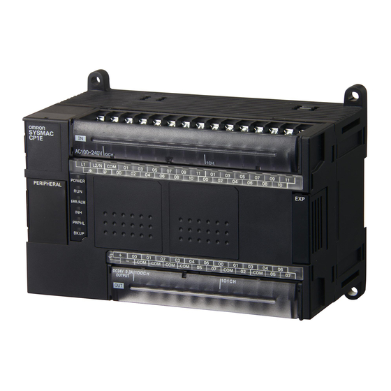
CP1E CPU Unit Software
Brand:
OMRON
| Category:
Software
| Size: 16 MB
Table of Contents
Introduction
5
Intended Audience
5
CP1E CPU Unit Manuals
6
I/O Allocation
7
I/O Memory
7
Overview
7
PLC Setup
7
Manual Structure
9
Terminology and Notation
10
Table of Contents
12
Safety Precautions
22
Precautions for Safe Use
25
Regulations and Standards
27
Related Manuals
28
Overview
29
Basic Operating Procedure
29
Section 1 Overview
30
CP1E Overview
30
Overview of Features
30
Basic Operating Procedure
31
Internal Memory in the CPU Unit
33
Memory Areas and Stored Data
33
Transferring Data from a Programming Device
33
2-1 Internal Memory in the CPU Unit
34
CPU Unit Memory Backup Structure
34
Internal Memory in the CPU Unit
34
Built-In Ram
34
Built-In Eeprom
34
Memory Areas and Stored Data
35
Backup
35
Index
35
Transferring Data from a Programming Device
36
Backup
36
CPU Unit Operation
37
3-1 CPU Unit Operation
38
Overview of CPU Unit Operation
38
CPU Unit Operation
38
CPU Unit Operating Modes
39
Operating Modes and Operation
40
Backing up Memory
41
CPU Unit Memory Configuration
41
Backing up Ladder Programs and PLC Setup
42
I/O Memory Backup
42
I/O Memory Backup Time
43
Initializing I/O Memory at Startup
44
Understanding Programming
45
Section 4 Understanding Programming
46
Programming
46
User Programs
46
Program Capacity
47
Basics of Programming
47
Tasks, Sections, and Symbols
50
Overview of Tasks
50
Overview of Sections
50
Overview of Symbols
50
Programming Instructions
52
Basic Understanding of Instructions
52
Operands
53
Instruction Variations
54
Execution Conditions
54
Input-Differentiated Instructions
55
Specifying Data in Operands
56
Specifying Addresses
56
Data Formats
57
I/O Refresh Timing
59
Cyclic Refreshing
59
Immediate Refresh
59
Constants
60
Specifying Offsets for Addresses
63
Overview
63
Application Examples for Address Offsets
65
Ladder Programming Precautions
66
Special Program Sections
66
Section 5 I/O Memory
70
Overview of I/O Memory Areas
70
I/O Memory Areas
70
I/O Memory Area Address Notation
73
I/O Memory Areas
73
I/O Memory Areas
74
Overview of Built-In Functions and
75
I/O Bits
75
Quick-Response Inputs
75
Work Area (W)
76
Holding Area (H)
77
Data Memory Area (D)
79
Timer Area (T)
81
Counter Area (C)
83
Auxiliary Area (A)
85
Condition Flags
87
Clock Pulses
89
I/O Allocation
91
Section 6 I/O Allocation
92
Allocation of Input Bits and Output Bits
92
I/O Allocation
92
I/O Allocation Concepts
93
Allocations on the CPU Unit
93
Allocations to Expansion Units and Expansion I/O Units
94
Allocations for Expansion Units
96
PLC Setup
97
Section 7 PLC Setup
98
Overview of the PLC Setup
98
PLC Setup Settings
99
Startup and CPU Unit Settings
99
Timing and Interrupt Settings
99
Input Constant Settings
100
Built-In RS-232C Port
101
Serial Option Port
104
Built-In Inputs
107
High-Speed Counter Settings
107
Interrupt Input Settings
108
Pulse Output 0 Settings
109
Pulse Output 1 Settings
110
Built-In AD/DA: Built-In Analog I/O Settings
112
PWM Outputs 5
114
Serial 6
114
Analog I/O Function 7
114
Interrupts
114
Overview
114
Built-In Functions
114
Input Interrupts
115
Overview
115
Overall Procedure for Using CP1E Built-In Functions
115
Terminal Allocations for Built-In Functions
116
Specifying the Functions to Use
116
Selecting Functions in the PLC Setup
116
Allocating Built-In Input Terminals
118
Allocating Functions to Built-In Input Terminals
118
Allocating Built-In Output Temrinals
120
Allocating Functions to Built-In Output Terminals
120
Quick-Response Inputs
121
9-1 Quick-Response Inputs
121
Overview
121
Flow of Operation
121
10-1 Interrupts
122
Overview
122
Creating Ladder Programs
124
Application Example
125
Scheduled Interrupts
125
Interrupt Task Priority and Order of Execution
125
Duplicate Processing in each Task
125
Interrupts
126
Overview
126
Input Interrupts
127
Overview
127
Flow of Operation
128
Application Example
131
Interrupt Task
133
Scheduled Interrupts
134
Overview
134
Flow of Operation
135
Precautions for Using Interrupts
137
Interrupt Task Priority and Order of Execution
137
Related Auxiliary Area Words and Bits
137
Duplicate Processing in each Task
137
High-Speed Counters
139
Section 11 High-Speed Counters
140
Overview
140
Flow of Operation
141
Specifications
145
High-Speed Counter Inputs
146
Pulse Input Methods Settings
146
Pulse + Direction Input
147
Counting Ranges Settings
148
Reset Methods
149
Phase-Z Signal + Software Reset
149
Reading the Present Value
150
Software Reset
150
Frequency Measurement
151
High-Speed Counter Interrupts
152
Overview
152
Present Value Comparison
155
Target Value Comparison
155
Range Comparison
158
High-Speed Counter Interrupt Instruction
159
Related Auxiliary Area Bits and Words
164
Application Example
165
System Configuration
166
Programming Example
167
Overview
170
Flow of Operation
171
Pulse Outputs
173
Connecting the Servo Drive and External Sensors
173
Specifications
178
Positioning Control
179
Positioning Control Configuration
179
Relative Positioning and Absolute Positioning
179
Application Example
181
Jogging
183
High-Speed Jogging
183
Low-Speed Jogging
183
Application Example
183
Defining Origin Position
186
Origin Searches
186
Flow of Operation
187
Settings in PLC Setup
187
Origin Search Instructions
190
Origin Search Operations
191
Origin Return
198
Changing the Present Value of the Pulse Output
199
Reading the Pulse Output Present Value
200
Related Auxiliary Area Flags
201
Application Examples
202
Vertically Conveying Pcbs (Multiple Progressive Positioning)
202
Feeding Wrapping Material: Interrupt Feeding
207
Precautions When Using Pulse Outputs
210
Pulse Output Pattern
215
Speed Control (Continuous Mode)
215
Positioning Control (Independent Mode)
217
PWM Outputs
223
PWM Outputs (Variable-Duty-Factor Pulse Outputs)
224
Flow of Operation
225
Ladder Program Example
225
14-1 Serial Communications
228
Types of CPU Units and Serial Ports
228
Serial Communications
228
Overview of Serial Communications
229
Program-Free Communications with Programmable Terminals
231
Overview
231
Flow of Connection
232
PLC Setup and PT System Settings
232
No-Protocol Communications with General Components
234
Overview
234
Flow of Operation
235
PLC Setup
235
Related Auxiliary Area Bits and Words
236
Modbus-RTU Easy Master Function
237
Overview
237
Flow of Operation
237
Setting and Word Allocation
238
DM Fixed Allocation Words
238
Error Codes
239
Programming Examples
240
Serial PLC Links
246
Overview
246
Flow of Operation
247
PLC Setup
247
Operating Specifications
249
Allocated Words
252
Serial Option Port
253
Example Application
254
Connecting the Host Computer (Not Including Support Software)
256
Overview
256
Flow of Operation
256
Command/Response Format and List of Commands
257
Section 15 Analog I/O Function
260
Overview
260
Flow of Operation
260
Analog I/O Specifications
264
Analog Input and Output Signal Ranges
265
Analog Input Signal Ranges
265
Analog Output Signal Ranges
267
Special Functions
269
I/O Allocation and Related Auxiliary Area Flags
270
I/O Allocation
270
Related Auxiliary Area Flags
270
PID Temperature Control
272
Overview
272
Flow of Operation
273
Application Example
274
Other Functions
275
Clock
277
DM Backup Function
278
Backing up and Restoring DM Area Data
278
Related Auxiliary Area Bits
279
Procedure
280
Security Functions
282
Ladder Program Read Protection
282
Ethernet Option Board
285
Features and Specifications
286
Ethernet Option Board Function Guide
286
Features
287
Specifications
289
Software Configuration
289
FINS Communications
290
Differences in Version of the Ethernet Option Board
292
Startup Procedure
293
Settings
295
Ethernet Option Board Setup
295
Transferring Data from the CPU Unit
296
Default Settings
297
Web Browser Setting Function
299
Unit Information
305
Unit Status
306
Fins Status
307
Memory Allocations
309
DM Area Allocation
309
Mode Setting
310
Subnet Mask
311
CIO Area Allocation
314
Error Status
315
Trouble Shooting
316
Error Log
316
Error Codes
317
Error Status
319
Connection Method with the CX-Programmer
320
Network Installation
323
Devices Required for Constructing a Network
323
Comparison with Previous Models
325
Programming Devices Usable with the CP1E
328
Overview of CX-Programmer
329
CX-Programmer
329
CX-Programmer Flow from Startup to Operation
329
Help
332
Creating a Ladder Program
333
Inputting a Ladder Program
333
Automatic Symbol Name Creation
339
Automatic I/O Comment Creation
339
Saving and Reading Ladder Programs
340
Editing Ladder Programs
341
Inputting Rung Comments
343
Connecting Online to the CP1E and Transferring the Program
344
Connecting Online
344
Changing Operating Modes
345
Transferring a Ladder Program and the PLC Setup
346
Starting Operation
347
Online Monitoring and Debugging
349
Monitoring Status
349
Force-Set/Reset Bits
351
Online Editing
352
Appendices
355
Instruction Functions
356
A-1-1 Sequence Input Instructions
356
A-1-2 Sequence Output Instructions
357
A-1-3 Sequence Control Instructions
359
A-1-4 Timer and Counter Instructions
361
Comparison Instructions
364
A-1-6 Data Movement Instructions
366
A-1-7 Data Shift Instructions
369
A-1-8 Increment/Decrement Instructions
371
A-1-9 Symbol Math Instructions
372
A-1-10 Conversion Instructions
376
A-1-11 Logic Instructions
380
Logic Instructions
380
A-1-12 Special Math Instructions
381
A-1-13 Floating-Point Math Instructions
381
A-1-14 Table Data Processing Instructions
384
Data Control Instructions
385
Subroutine Instructions
389
A-1-17 Interrupt Control Instructions
390
A-1-18 High-Speed Counter/Pulse Output Instructions
391
A-1-19 Step Instructions
398
A-1-20 Basic I/O Unit Instructions
399
A-1-21 Serial Communications Instructions
403
A-1-22 Clock Instructions
404
A-1-23 Failure Diagnosis Instructions
405
A-1-24 Other Instructions
405
Auxiliary Area Allocations by Address
406
A-2-1 Read-Only Words
406
Read-Only Words
406
A-2-2 Read/Write Words
424
Response Performance
434
A-3-1 I/O Response Time
434
A-3-2 Interrupt Response Time
436
A-3-3 Serial PLC Link Response Performance
437
A-3-4 Pulse Output Start Time
438
A-3-5 Pulse Output Change Response Time
438
PLC Operation for Power Interruptions
439
Description of Operation
440
Instruction Execution for Power Interruptions
440
Index
443
Revision History
447
Advertisement
Advertisement
Related Products
Omron SYSMAC CP1E-E Series
Omron SYSMAC CP1E-N Series
Omron SYSMAC CP1E-NA Series
Omron CP Series
OMRON CX-PROGRAMMER - INTRODUCTION GUIDE
Omron CX-Programmer 5.0
Omron CX-Process Tool
Omron CX-Motion-NCF 1.9
Omron CS Series
Omron CX-Supervisor 2.0
OMRON Categories
Blood Pressure Monitor
Controller
Accessories
Switch
Inverter
More OMRON Manuals
Login
Sign In
OR
Sign in with Facebook
Sign in with Google
Upload manual
Upload from disk
Upload from URL