Sign In
Upload
Manuals
Brands
MGE UPS Systems Manuals
UPS
EX 11RT
MGE UPS Systems EX 11RT Manuals
Manuals and User Guides for MGE UPS Systems EX 11RT. We have
3
MGE UPS Systems EX 11RT manuals available for free PDF download: Installation And User Manual, Quick Start Manual
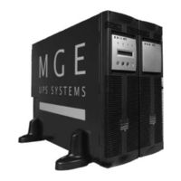
MGE UPS Systems EX 11RT Installation And User Manual (76 pages)
MGE Installation and User Manual UPS EX 5/7/11RT
Brand:
MGE UPS Systems
| Category:
UPS
| Size: 3 MB
Table of Contents
Revision History
3
Table of Contents
5
Important Safety Instructions
10
Certification Standards
10
CAUTION: Safety of Persons
11
CAUTION: Product Safety
11
Special Precautions
11
Environment
11
CAUTION: Record All Serial Numbers
12
Symbol Usage
13
Section Descriptions
13
Introduction
15
Optional Accessories (See Section 1.5 for Description)
16
System Electrical Characteristics
17
Transformer Module Characteristics Ratings
17
UPS Characteristics System Ratings
17
And Optional Transformer Module
18
Battery Module Ratings
18
Standard Configuration
18
Tower Configuration
18
And Optional Transformer Module
19
System Dimensions and Weights
19
Rack Configuration
19
Rear Panel of the Battery Module
20
Rear Panel of the Power Module
20
Rear Panel Components
20
Power Module EX 5/7/11 RT
20
Battery Module EXB 5/7/11RT with Remote Emergency Power off (REPO) Function
20
Rear Panel of the Optional Transformer Module. (PN 86211)
21
View of Typical Control Panel Interface
21
EX RT Transformer Module
21
Power Module Display and Control Panel
21
Optional Accessories
22
Power Module Rail Kit
22
1.5.2 Battery/Transformer/Cla Module Rail Kit
22
Typical Back-Up Time with Multiple Exb's at Full Load
23
Multiple Battery Module Backup Time at Full Load
23
Battery Extension Cable Kit
23
Optional Configurations
23
Battery Integration Kit with Casters
24
Input/Output Box
24
Transformer Module
24
Power Module
24
Battery Modules
24
Typical Transformer Module Contents and Connections
25
Transformer Module - for Use with EX 5/7/11RT Power Module
25
CLA Module Contents and Connections
26
Battery Backup Time Chart
26
CLA Charger Module
26
1 Scope
15
EX RT Model Descriptions and Contents
15
Setup and Installation
27
2 Scope
27
Unpacking and Parts Check
27
Contents of EX 5/7/11RT Power Module
28
Contents of Standard EX 5/7/11RT Systems
28
Contents of EXB 5/7/11RT Battery Module
29
Installation in Tower Configuration
30
Optional Transformer Module
30
Installation in Rack Mounting Configuration
31
Adjustment of Front Panel Logo and Control Panel for Rack Orientation
31
Accessing Battery Pack
32
Prepare Battery Module for Rack Mounting
32
Power, Battery, Transformer, and CLA Charger Module Rack Mounting
33
Input/Output Box Bracket System
34
RS232 Communication Cable Connection
35
Communication Ports
35
Connecting the RS232 Communication Port
35
Relay Pin Connections for Communication Port
36
Management Card Installed
36
Connecting the Dry (Relay) Contact Communication Port
36
Installation of Optional Transverse Card
36
Using a Contact Normally Open Switch
38
Contact Normally Closed Switch
38
Remote Emergency Power off (REPO) Communication Port
38
Power Module I/O Box Terminal Block Diagram
39
System Connections
39
Connections with Common Normal and Bypass AC Sources (Single Mains)
39
Normal AC Input and Output Cables Installation
40
For 120/208/240 Vac Outputs (Shown with One EXB)
41
Connecting EX RT Transformer Module
41
And Simplified Connection Diagram
42
Connections with Separate Normal and Bypass AC Sources (2 Mains)
42
Accessing Terminal Blocks for Input and Output Power Cables
43
System Connections as Frequency Converter (Without Bypass AC Source)
43
Rear View of Battery Module Cable Connections
44
Connection of Battery Module EXB
44
Connection of Optional CLA Module
45
Rear View of CLA Module Cable Battery and AC Input Connections
45
Operation
47
3 Scope
47
Initial Startup
47
Control Panel with Scroll up and down Buttons
48
UPS Personalization
48
Accessing Personalization with Front Panel Buttons
48
Configuration Used to Provide Cascade Redundancy to Critical Loads
49
Output Features
49
Local Settings
49
Battery Features
50
ON/OFF Features
50
Information Technology IT Network and Industrial Operating Modes
51
UPS Personalization through External Software
52
Final Startup Sequence
52
Operating Modes
53
Normal (Double Conversion) Mode
53
Load Level
53
Remaining Time
53
ECO Mode
54
Transfer, Threshold and End of Backup Time
55
Operation on Battery Power
55
Transfer to Battery Power
55
Return of Normal AC Source
56
Shutdown
56
Maintenance
57
4 Scope
57
Troubleshooting
57
Battery Fault
58
Troubleshooting Requiring MGE After-Sales Support
58
Hot Swapping the Power Module
59
Re-Connecting the Power Module
60
Hot Swapping the Battery Module
61
Disconnecting the Battery Module
61
Re-Connecting the Battery Module
61
Power Supplied as a Function of Input Voltage (Left and Permissible UPS Overloads as a Function of Time (Right)
63
Rear View of the Battery Module
61
Appendix
63
5 Electrical Specifications
63
System Input/Output Power Ratings
63
System Overload Characteristics
63
System Backup Characteristics
64
System Short Circuit Protection
64
Accessories Electrical Characteristics
64
Heat Rejection
66
Environmental Characteristics
66
MGE Warranty & Proprietary Rights for Single Phase Products
67
MGE Standard Single Phase Warranty
67
Proprietary Rights Statement
67
Warranty and Product Registration
68
Scenic Avenue Costa Mesa, CA
75
Reorder Form
75
Mge Ups Systems
76
Advertisement
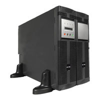
MGE UPS Systems EX 11RT Installation And User Manual (72 pages)
MGE UPS SYSTEMS, INC. User Manual Power Supply EX 5RT / EX 7RT/ EX 11RT
Brand:
MGE UPS Systems
| Category:
UPS
| Size: 4 MB
Table of Contents
Important Safety Instructions
2
Certification Standards
2
Product Safety
3
Special Precautions
3
Safety of Persons
3
How to Use this Manual and Symbol Usage
3
CAUTION: Record All Serial Numbers
4
Revision History
5
Table of Contents
7
Warranty and Product Registration
9
Introduction
13
Scope
13
EX RT Model Descriptions and Contents
14
Optional Accessories (See Section 1.5 for Description)
15
And Optional Transformer Module
16
Battery Module Ratings
16
Standard Configurations
16
Tower Configuration
16
System Electrical Characteristics
16
Power Module Ratings
16
Rack Configuration
17
Transformer Module
17
Rear Panel of the Battery Module
18
Rear Panel of the Power Module
18
Rear Panels
18
Battery Module EXB 5/7/11 RT with Emergency Power off (EPO) Function
18
Power Module EX 5/7/11 RT
18
EX RT Transformer Module
19
Rear Panel of the Optional Transformer Module. (PN 86003)
19
View of Typical Control Panel Interface
19
Display and Control Panel
19
Optional Accessories
20
Battery/ Transformer/Cla Module Rail Kit
20
Power Module Rail Kit
20
Rack Mounting
20
Power Module Rack Mounting Kit
20
Battery Extension Cable Kit
21
Battery Module with Remote Emergency Power off (REPO) Function
21
Typical Back-Up Time with Multiple Exb's at Full Load
21
Battery Integration Kit with Casters
22
Input/Output Box
22
Transformer Module
23
Typical Transformer Module Contents and Connections
23
Battery Backup Time Chart
24
CLA Module (Long Backup Time Charger)
24
Recommended Batteries
24
EX 5/7/11 RT System
25
Setup and Installation
25
Scope
25
Unpacking and Parts Check
25
Contents of EX 5/7/11 RT System
26
EX 7RT (PN 86070) / EX 11RT (PN 86110) System
27
Transformer Module
28
Installation in Tower Configuration
28
Installation in Rack Mounting Configuration
29
Adjustment of Front Panel Logo and Control Panel for Rack Orientation
29
Accessing Battery Pack
30
Prepare Battery Module for Rack Mounting
30
Rack Mounting of the Power Module Onto the Rails
31
Power or Battery Module Rack Mounting
31
B: Input/Output Box Bracket System
32
Input/Output Box Bracket System Installation
32
Rear Support Brackets Installation
32
RS232 Communication Cable Connection
33
Communication Ports
33
Connecting the RS232 Communication Port
33
Management Card Installed
34
Relay Pin Connections for Communication Port
34
Connecting the Dry (Relay) Contact Communication Port
34
Installation of Optional Network Management Card
34
Normally Closed Switch
36
Normally Open Switch
36
Remote Emergency Power off (REPO) Communication Port
36
A: Step 1 & 2; Typical Plastic and Metal Coupling Installations
37
Connecting the Input and Output Power Cables to the Input/Output Box
37
Flexible Cordage and Conduit Installations
37
C: I/O Box Terminal Block Diagram
38
B: Step 3; Typical Straight Metal Conduit Installation
38
Normal AC Input and Output Cables Installation
39
System Connections with Common Normal and Bypass AC Sources
39
Connecting EX RT Transformer
40
View of EX RT Transformer Connected Downstream for 120/208/240 Vac Outputs (Shown with One EXB)
40
Normal AC Input, Bypass AC, and Output Cables Installation
41
System Connections with Separate Normal and Bypass AC Sources
41
Accessing Terminal Blocks for Input and Output Power Cables
42
System Connections as Frequency Converter (Without Bypass AC Source)
42
Connection of Battery Module, EXB
43
Rear View of Battery Module Cable Connections
43
Connection of CLA Module
44
Rear View of CLA Module Cable Battery and AC Input Connections
44
Operation
45
Scope
45
Initial Startup
45
Control Panel with Scroll up and down Buttons
46
UPS Personalization
46
Accessing Personalization with Front Panel Buttons
46
Configuration Used to Provide Full Redundancy (2N) to Critical Loads
47
Local Settings
47
Output Features
47
Battery Features
48
ON/OFF Features
48
Accessing Personalization through External Software
48
Final Startup Sequence
48
Operating Modes
49
Normal (Double Conversion) Mode
49
ECO Mode Display
50
ECO Modes
50
Transfer, Threshold and End of Backup Time
51
Operation on Battery Power
51
Transfer to Battery Power
51
Return of Normal AC Source
52
Shutdown
52
Network and Industrial Modes of Operation
53
Maintenance
53
Scope
53
Information Technology (IT) Network and Industrial Operating Modes
53
Troubleshooting
54
Troubleshooting Requiring MGE After-Sales Support
55
Hot Swapping the Power Module
56
Re-Connecting the Power Module
57
Hot Swapping the Battery Module
58
Disconnecting the Battery Module
58
Re-Connecting the Battery Module
58
Rear View of the Battery Module
58
Power Supplied as a Function of Input Voltage (Left), and Permissible UPS Overloads as a Function of Time (Right)
59
Appendix
59
Electrical Specifications
59
System Input/Output Power Ratings
59
System Overload Characteristics
59
System Backup Characteristics
59
System Short Circuit Protection
60
Accessories Electrical Characteristics
60
Heat Rejection
60
Environmental Characteristics
60
MGE Warranty & Proprietary Rights for Single Phase Products
61
Mge Customer Care Center
63
Reorder Form
69
MGE UPS Systems EX 11RT Quick Start Manual (8 pages)
EX RT series Transformer Module
Brand:
MGE UPS Systems
| Category:
UPS
| Size: 0 MB
Table of Contents
Standard Features
1
Quick Start
3
Warranty and Product Registration
3
STEP 1 EX RT Transformer Module Unpacking and Parts Check
3
STEP 2 EX RT Transformer Module Tower Configuration
3
EX RT Transformer Module
4
Rack Configuration
4
Rack Installation
4
STEP 4 Systems Connections
5
Advertisement
Advertisement
Related Products
MGE UPS Systems Pulsar EX10Rack
MGE UPS Systems Pulsar EX15Rack
MGE UPS Systems Pulsar EX 1000
MGE UPS Systems Pulsar EX15
MGE UPS Systems Pulsar EX10
MGE UPS Systems Pulsar EX 1500
MGE UPS Systems EX 11
MGE UPS Systems Pulsar EX 1000RT
MGE UPS Systems Pulsar EX 1500RT
MGE UPS Systems Pulsar EX40
MGE UPS Systems Categories
UPS
Power Supply
Network Card
Power distribution unit
Medical Equipment
More MGE UPS Systems Manuals
Login
Sign In
OR
Sign in with Facebook
Sign in with Google
Upload manual
Upload from disk
Upload from URL