Sign In
Upload
Manuals
Brands
Honeywell Manuals
Fire Alarms
NOTIFIER ID2000 Series
Honeywell NOTIFIER ID2000 Series Manuals
Manuals and User Guides for Honeywell NOTIFIER ID2000 Series. We have
3
Honeywell NOTIFIER ID2000 Series manuals available for free PDF download: Manual, Installation & Commissioning Manual, Operating Manual
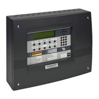
Honeywell NOTIFIER ID2000 Series Manual (147 pages)
Fire Panel Configuration Tool
Brand:
Honeywell
| Category:
Control Panel
| Size: 1.85 MB
Table of Contents
Table of Contents
3
1 Introduction
7
PC Specification
8
Installation
8
Starting the Tool
9
Authentication Option
9
Connecting a PC to the Panel
10
Tool Overview and Menus
11
Tool Language Setting
11
Tool Window
11
File Menu
12
Panel Menu
13
Repeater Menu
15
View Menu
18
Edit Menu
18
Communications Menu
20
System Parameters Menu
24
Tools Menu
26
External Systems Menu
28
Help Menu
29
Toolbar Options
29
Loop Display
30
2 Panel Settings Configuration
31
Specification Tab
31
Loop Setting Tab
34
Port/Printer Options Tab
36
Pulse Options Tab
38
ÜE Configuration Tab
40
Remote Fire Outputs Tab
42
Tests Tab
44
Disablements Tab
45
Day/Night Mode Tab
48
Other Options Tab
50
Extinguishing System Tab
53
Alarm Coincidence Tab
54
Vds Network Options
55
3 Loop Devices Configuration
56
Select a Device
56
Edit Device
60
Sensors
60
Modules
71
Define Sounder Tone Slots
76
4 Control Matrix Configuration
78
Introduction
78
EN54 Requirements
78
Input Event Statement
79
Output Event Statement
82
Extinguishing System Function
85
Logic Operations with Transfer Flags
89
Review/Edit Control Matrix Entries
93
Review Entries
93
Amend/Create/Delete Entry
93
Print Menu
94
Thermal Alarm Verification Delay
94
Defining a Control Matrix Rule
95
Input Event
95
Output Event
102
5 Time-Of-Day Configuration
112
Introduction
112
Manual Override
113
Editing Procedure
114
6 Network Configuration
116
Introduction
116
Master/Slave Network
117
Introduction
117
Advertisement
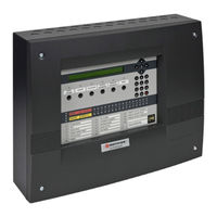
Honeywell NOTIFIER ID2000 Series Installation & Commissioning Manual (68 pages)
Brand:
Honeywell
| Category:
Control Panel
| Size: 5.87 MB
Table of Contents
Table of Contents
3
1 Introduction
6
CE Marking
6
System Design and Planning
6
Personnel
6
General
7
Date-Dependent Functions
7
Installation: Sections
7
2 Installation Guide
8
How to Use this Guide
8
Related Documents
8
Warnings and Cautions
8
Tips
8
Glossary of Icons
9
Pre-Installation Check List
10
Some Do's and Dont's
10
Transient Protection
11
Installation
12
Checking Your Panel for Damage
12
What to Do if Your Module Is Damaged
13
Back Box Fixing
14
Electronics Modules
15
Replacing the Electronics Modules
16
Flush Mounting Bezel (Optional)
16
Mounded Front Covers
17
3 Cabling
19
Cabling Instructions
19
Cable Terminations
20
Cable Installation Notes
21
Introduction
21
Quality of Cable and of Cable Installation
21
EMC Considerations
22
Screen Termination
22
Ferrite Sleeves (Optional)
22
MICC Cables
22
4 Sensors and Modules
23
EN54 Requirements
23
Loop Devices - Sensors and Mcps
23
Loop Devices - Isolators
23
Loop Wiring Testing
23
5 Panel Electronics Modules
24
Introduction
24
Kit PSU3A
25
Procedure
25
Dual Transmission Path/Booster Module
28
Main Chassis
30
Main Chassis Configurations
30
Procedure
30
Extension Chassis
31
Zones 17-80 LED Extension Chassis
31
Extension Chassis (with Printer)
31
PRN-ID Printer
32
Fitting the Paper Roll
32
Printer Used with Stainless Steel Cover
33
Display PCB
34
Base PCB
35
Fitting the Replacement Base PCB
36
Cables and Wiring
36
Processor PCB
37
Loop Interface PCB
38
1Cables and Wiring
38
Isolated RS232 Interface PCB
39
Cables and Wiring
40
Isolated RS485 Interface PCB
41
1Cables and Wiring
42
Label Inserts
42
6 Repeaters and Network
43
Connecting Repeaters
43
Network Connections
44
7 Vdu
45
8 Commissioning
46
Introduction
46
Preliminary Checks
46
Powering the Panel
47
External Wiring
47
Introduction
47
Loop Checks before Connecting Wiring
48
Connecting the Loop Wiring to the Panel
49
Loop Checks after Connecting Wiring
49
Auxiliary Outputs Check
50
Sounder Circuits Check
50
Fault Relay Wiring
50
Batteries
51
Connecting the Batteries
51
Battery Disposal
52
Earth Fault Monitoring
52
Volt-Free Contact Output Option
53
Repeaters
53
Configuration and Handover
53
System Test
53
Zone Walk Test
53
Control Output Test
53
9 Maintenance
54
Routine Testing
54
Batteries
54
Cleaning
54
Appendix 1 Fault Messages and Possible Meanings
55
Appendix 2 Specifications
60
Appendix 3 ID2000 System Design Guide
65
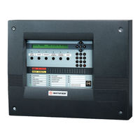
Honeywell NOTIFIER ID2000 Series Operating Manual (55 pages)
Brand:
Honeywell
| Category:
Fire Alarms
| Size: 1.78 MB
Table of Contents
Table of Contents
2
1 Introduction
4
Associated Documents
4
The ID2000 Panels
4
Cleaning
5
2 Panel Controls and Indicators
6
3 Automatic Alarms - What to Do
7
Fire
7
Pre-Alarm
8
Fault
9
4 Operator Actions at Panel
10
Introduction
10
Top Level Display
11
Passcodes
12
Mute Buzzer
12
Accept
13
Evacuate
14
Silence (and Re-Start) Sounders
15
Reset
15
Lamp Test and Display Control
16
Lamps Test in Sequence
16
All Lamps Lit and LCD Adjust
16
System Test
17
Zone Walk Test
19
Control Output Test
21
Sensor Automatic Test
23
Replace (VIEW) Sensor
24
Disablement and Enablement
26
Individual Device
28
Complete Zone
29
Outputs
30
Complete Zone Via Remote Switch
31
Time-Of-Day Control
31
Display, Log and Print
32
1Display And/Or Log Device Data
33
2Print Device Data
37
3Display and Re-Print Event Log
39
4Printer Control Modes
40
Setting the Clock
41
Select Day or Night Mode
42
Set Language
42
5 Non-Latched Input Operation
43
Advertisement
Advertisement
Related Products
Honeywell NOTIFIER IFS-2600
Honeywell iPGSM-COM
Honeywell NOTIFIER ID61
Honeywell NOTIFIER ID62
Honeywell Farenhyt IFP-300B
Honeywell Notifier FirstCommand Series
Honeywell Notifier FAAST LT NFXI-ASD Series
Honeywell NOTIFIER ID2002
Honeywell IDENT-KEY
Honeywell E-Mon IDR-8
Honeywell Categories
Thermostat
Controller
Control Unit
Security Camera
Accessories
More Honeywell Manuals
Login
Sign In
OR
Sign in with Facebook
Sign in with Google
Upload manual
Upload from disk
Upload from URL