Festo CPX Manuals
Manuals and User Guides for Festo CPX. We have 6 Festo CPX manuals available for free PDF download: System Manual, Electronic Manual, Assembly Instructions Manual, Instructions And Assembly, Assembly Instructions

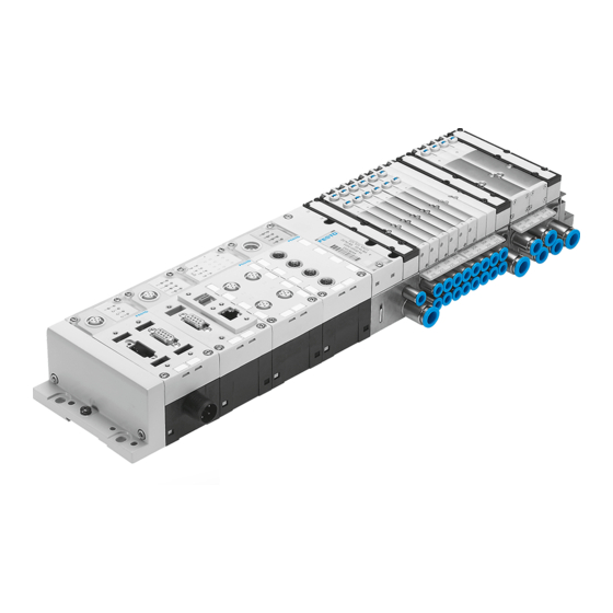
Festo CPX System Manual (235 pages)
Installing and commissioning CPX terminals
Brand: Festo
|
Category: Touch terminals
|
Size: 3 MB
Table of Contents
Advertisement
Festo CPX Electronic Manual (221 pages)
Brand: Festo
|
Category: Touch terminals
|
Size: 2 MB
Table of Contents

Festo CPX Electronic Manual (142 pages)
Brand: Festo
|
Category: Touch terminals
|
Size: 2 MB
Table of Contents
Advertisement

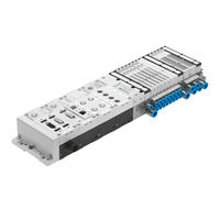
Festo CPX Instructions And Assembly (7 pages)
Terminal CPX / Valve terminal MPA
Brand: Festo
|
Category: Controller
|
Size: 9 MB
Table of Contents

Festo CPX Assembly Instructions Manual (7 pages)
Brand: Festo
|
Category: Touch terminals
|
Size: 1 MB
Table of Contents

Festo CPX Assembly Instructions (5 pages)
Terminal CPX
Brand: Festo
|
Category: Touch terminals
|
Size: 0 MB