Sign In
Upload
Manuals
Brands
EMC Manuals
Server
Data Domain DS60
EMC Data Domain DS60 Manuals
Manuals and User Guides for EMC Data Domain DS60. We have
1
EMC Data Domain DS60 manual available for free PDF download: Hardware Manual
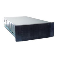
EMC Data Domain DS60 Hardware Manual (186 pages)
Expansion Shelf Installation and FRU Replacement
Brand:
EMC
| Category:
Server
| Size: 11 MB
Table of Contents
Table of Contents
3
Figures
7
Tables
11
Preface
13
Revision History
15
Document Revision History
15
Chapter 1 Technical Specifications
17
Disk Drive Type
18
Network Cabling
18
System Operating Limits
18
Type
18
Limits
18
Requirements
18
Shipping and Storage Requirements
19
Dimensions and Weight
19
Shelf with no Frus Installed, Dimensions and Weight
19
Shelf with Frus Installed, Dimensions and Weight
19
Weight
19
Chapter 2 Shelf Installation and Removal
21
Shelf Installation
22
Installing Rails
22
Pins for Non-EMC Racks
22
Rail Installation
23
Installing the Right Rail to the Rear Channel
24
Working with the Portable Lift
25
Installing the Right Rail to the Front Channel
25
Reconfiguring the Lift with Voyager Kit
26
Reconfiguring the Portable Lift with the Voyager Conversion Kit
26
Adjusting the Arms for a Frontal Lift
27
Installing the Shelf Onto the Rails
27
Adjusting the Lift Arm Bar to Just under 17 Inches
27
Sliding the Shelf Chassis into the Rails
29
Unlocking the Casters
29
Locking the Casters
30
Removing the Straps
30
Inserting and Securing the Top Cover and Chassis
31
Inserting and Securing the Chassis to the Cabinet
31
Removing Semi-Captive Screws
32
Inserting and Securing the Chassis to the Cabinet
32
Installing Ears to Rack Using Truss Head Screws
33
Installing Top Cover Using Truss Head Screws
34
Truss Head Screws
34
Shelf Removal
35
Working with the Portable Lift
35
Planning Your Lift
35
Removal of Semi-Captive Screws
35
Removing the Front Bezel
36
Best Practice: Using the Portable Lift Adjacent to the Long Side of the Shelf
36
Planning Your Lift
36
Pulling the Shelf Chassis out
37
Removing the Front Bezel
37
Removing a Shelf from the Cabinet
38
Pulling the Chassis out (Two Shoulder Screw Configuration)
38
Example of Adjusting the Lift Arm/Tray to Just under 17-Inches
39
Releasing Chassis from the Rails
40
Removing the Shipping Screws, if Present
40
Pulling the Chassis out (Two Shoulder Screw Configuration)
41
Reconfiguring the Alum-A-Lift with the Conversion Kit
41
Locking the Casters
42
Removing a Shelf from Rails more than 49" above the Floor
43
Using the Lift on a Shelf more than 49" above the Floor
44
Unlocking the Casters
44
Tightening the Straps
44
Adjusting the Arm for a High Rail Position
45
Locking the Casters
46
Removing a Shelf from Rails more than 49" above the Floor
46
Unlocking the Casters
47
Tightening the Straps
47
Using the Lift on a Shelf 49" or Less above the Floor
48
Support Table
48
Removing the Straps
48
Adjusting the Arm for a Low Rail Position
49
Locking the Casters
50
Removing a Shelf from Rails 49" or Less above the Floor
50
Tightening the Straps
51
Unlocking the Casters
51
Cable Management Tray Installation (Underneath)
52
Racks and Rails
52
Removing the Straps
52
Installing the 1U Cable Management Tray
53
Blue Tab on Rail Must be Pushed in
53
Installing/Securing Rails - Front
54
Installing/Securing Rails - Rear
54
Installing Tray
55
Spring Clips - Push up to Release Tray
55
Opening the Cable Chain Lids
55
Cable Positioning in Cable Chains
56
Attaching Cable Chains to Tray
57
Installing the Chassis Bracket into the Shelf
57
Installing the Chassis Bracket
58
Installing the Bezel
58
Disconnecting Cables for an Shelf Installed with the 1U Cable Management Tray
59
1U Cable Tray Removal
59
Removing the 1U Cable Tray
59
Remove the Bezel
59
Remove Chassis Bracket from Chassis
60
Unclip the Cable Chains from the Tray
61
Push Spring Clips up to Release the Tray
61
Non-EMC Rack Installation
62
Shelf Rail Installation in Non-EMC Racks
62
Remove the Tray
62
Screw and Nut Placements
63
Shelf Rail Kit Contents
63
Required Tools
63
Pins for Non-EMC Racks
66
List of Parts Used in Illustration, Shelf Rail Installation
67
Rail Installation
68
Securing a Rail with a Single Screw
70
List of Parts Used in Illustration, Location of Securing Screws and Alignment Pins
70
Location of Securing Screws and Alignment Pins
71
List of Parts Used in Nutbar Installation Illustration
72
Nutbar Installation (Left Nutbar Shown)
73
Removing the Universal Rails
74
Chapter 3 Removing and Replacing Frus
75
Common Procedures
76
Avoiding Electrostatic Discharge (ESD) Damage
76
Emergency Procedures (Without an ESD Kit)
76
Hardware Acclimation Times
77
Hardware Acclimation Times (Systems and Components)
77
Removing, Installing, or Storing Replaceable Units
78
Unpacking a Part
79
Standard Touch Point Colors
79
Power Supply Replacement
80
Identify the Failed Power Supply Unit
80
Removing a Power Supply Unit
81
Replacing a Power Supply
81
Verify the Power Supplies
82
Complete the Procedure
83
LCC Replacement
83
Identify the Failed
83
Removing an LCC
84
Replacing an LCC
84
Verify the
85
Complete the Procedure
86
Disk Replacement
86
Identify the Failed Drive
86
Status Lights
87
Opening the Console
89
Removing the Front Bezel
89
Pulling the Shelf Chassis out
90
Removing the Front Bezel
90
Removing a Disk Drive
91
Pulling the Chassis out (Two Shoulder Screw Configuration)
91
Installing a Disk
92
Removing a Disk Drive
92
Verify the Operation of the New Disk Drive
93
Installing a Disk
93
Installing the Front Bezel
94
Complete the Procedure
94
Fan Replacement
94
Identify the Failed Fan Unit
94
Removing the Front Bezel
95
Pulling the Shelf Chassis out
96
Removing a Fan Module
96
Pulling the Chassis out (Two Shoulder Screw Configuration)
96
Installing a Fan
97
Verify the Fans
98
Installing the Front Bezel
99
Complete the Procedure
99
Chassis Removal
99
Working with the Portable Lift
99
Reconfiguring the Lift with Voyager Kit
100
Adjusting the Arms for a Frontal Lift
101
Reconfiguring the Portable Lift with the Voyager Conversion Kit
101
Removing a Power Supply Unit
102
Adjusting the Lift Arm Bar to Just under 17 Inches
102
Removing an LCC
103
Opening the Console
104
Removing the Front Bezel
104
Removing a Disk Drive
105
Removing the Front Bezel
105
Removing a Fan Module
106
Removing a Shelf from the Cabinet
107
Example of Adjusting the Lift Arm/Tray to Just under 17-Inches
108
Releasing Chassis from the Rails
109
Removing the Shipping Screws, if Present
109
Pulling the Chassis out (Two Shoulder Screw Configuration)
110
Reconfiguring the Alum-A-Lift with the Conversion Kit
110
Locking the Casters
111
Removing a Shelf from Rails more than 49" above the Floor
112
Chassis Replacement
113
Tightening the Straps
113
Unlocking the Casters
113
Reconfiguring the Portable Lift with the Voyager Conversion Kit
115
Adjusting the Lift Arm Bar to Just under 17 Inches
116
Sliding the Shelf Chassis into the Rails
118
Unlocking the Casters
118
Removing the Straps
119
Locking the Casters
119
Inserting and Securing the Chassis to the Cabinet
120
Removing Semi-Captive Screws
121
Installing Ears to Rack Using Truss Head Screws
122
Installing Top Cover Using Truss Head Screws
123
Truss Head Screws
123
Removal of Semi-Captive Screws
124
Installing a Disk
126
Installing the Front Bezel
128
DS60 Bezel Replacement
128
Removing the Front Bezel
128
Installing the Front Bezel
129
DS60 Cable Management Assembly (CMA) Bezel
129
Removing the CMA Front Bezel
129
Remove the Bezel
129
Removing the Front Bezel
129
Installing the CMA Front Bezel
130
DS60 Cable Management Assembly (CMA) Replacement
130
Removing the 1U Cable Tray
130
Remove the Bezel
130
Installing the Bezel
130
Remove Chassis Bracket from Chassis
131
Remove the Chassis Bracket
131
Push Spring Clips up to Release the Tray
132
Unclip the Cable Chains from the Tray
132
Installing the 1U Cable Tray
133
Remove the Tray
133
Spring Clips - Push up to Release Tray
133
Opening the Cable Chain Lids
134
Cable Positioning in Cable Chains
134
Attaching Cable Chains to Tray
135
Installing the Chassis Bracket into the Shelf
135
Installing the Chassis Bracket
136
Installing the Bezel
136
Connecting Cables to the Shelf
137
DS60 Rail Replacement
137
Working with the Portable Lift
137
Reconfiguring the Lift with Voyager Kit
138
Adjusting the Arms for a Frontal Lift
138
Reconfiguring the Portable Lift with the Voyager Conversion Kit
138
Removing a Power Supply Unit
139
Adjusting the Lift Arm Bar to Just under 17 Inches
139
Removing an LCC
140
Opening the Console
141
Removing the Front Bezel
141
Removing a Disk Drive
142
Removing a Fan Module
143
Removing a Shelf from the Cabinet
144
Example of Adjusting the Lift Arm/Tray to Just under 17-Inches
145
Releasing Chassis from the Rails
146
Removing the Shipping Screws, if Present
146
Pulling the Chassis out (Two Shoulder Screw Configuration)
147
Reconfiguring the Alum-A-Lift with the Conversion Kit
147
Locking the Casters
148
Removing a Shelf from Rails more than 49" above the Floor
149
Tightening the Straps
150
Unlocking the Casters
150
Removing the Universal Rails
151
Installing Rails
152
Pins for Non-EMC Racks
152
Rail Installation
153
Installing the Right Rail to the Rear Channel
154
Installing the Shelf Onto the Rails
155
Installing the Right Rail to the Front Channel
155
Sliding the Shelf Chassis into the Rails
157
Unlocking the Casters
157
Removing the Straps
158
Locking the Casters
158
Inserting and Securing the Top Cover and Chassis
159
Inserting and Securing the Chassis to the Cabinet (Shoulder Screw Configuration)
160
Installing Top Cover Using Truss Head Screws
162
Truss Head Screws
162
Replacing a Power Supply
163
Replacing an LCC
163
Removal of Semi-Captive Screws
163
Installing a Disk
164
Installing a Fan
165
Installing a Disk
165
Connecting Cables to the Shelf
166
Verify the Chassis Replacement
167
Installing the Front Bezel
167
DS60 Cable Management Assembly (CMA) Rail Replacement
167
1U Cable Tray Removal
167
Remove the Bezel
168
Remove Chassis Bracket from Chassis
168
Remove the Chassis Bracket
169
Unclip the Cable Chains from the Tray
169
Cable Management Tray Installation (Underneath)
170
Push Spring Clips up to Release the Tray
170
Remove the Tray
170
Blue Tab on Rail Must be Pushed in
172
Installing/Securing Rails - Front
172
Installing/Securing Rails - Rear
173
Installing Tray
173
Spring Clips - Push up to Release Tray
174
Opening the Cable Chain Lids
174
Cable Positioning in Cable Chains
174
Attaching Cable Chains to Tray
175
Installing the Chassis Bracket into the Shelf
175
Installing the Chassis Bracket
176
Installing the Bezel
176
Chapter 4 Adding Disks
177
Verify System Health
178
Identify the First Empty Disk Pack in the Target Enclosure
178
Enclosure
178
Locate the Target Enclosure in the Rack
179
Opening the Console
179
Removing the Front Bezel
179
Rack
179
Bezel
179
Pulling the Shelf Chassis out
180
Removing the Front Bezel
180
Out
180
Add New Disks
181
Pulling the Chassis out (Two Shoulder Screw Configuration)
181
Close the Shelf Chassis
182
Verify and Configure the New Storage
182
Installing a Disk
182
Chassis
182
Storage
182
Installing the Front Bezel
185
Bezel
185
Advertisement
Advertisement
Related Products
EMC Data Domain DD670
EMC DD640
EMC Data Domain DD890
EMC Data Domain DD860
EMC DS-16B
EMC Connectrix DS-32M2
EMC DS-4900B
EMC Connectrix DS-8B3
EMC DS-300B
EMC Connectrix DS-5300B
EMC Categories
Storage
Switch
Server
Enclosure
Network Hardware
More EMC Manuals
Login
Sign In
OR
Sign in with Facebook
Sign in with Google
Upload manual
Upload from disk
Upload from URL