Sign In
Upload
Manuals
Brands
Electrolux Manuals
Washer
ENV06
Electrolux ENV06 Manuals
Manuals and User Guides for Electrolux ENV06. We have
4
Electrolux ENV06 manuals available for free PDF download: Service Manual
Electrolux ENV06 Service Manual (176 pages)
Front loader washer
Brand:
Electrolux
| Category:
Washer
| Size: 4.67 MB
Table of Contents
Service Manual
1
Table of Contents
3
1 Ewm1000
5
Access to the Diagnostic Cycle
5
Rapid Reading of Alarms
5
Cancelling the Last Alarm
5
Phases of the Diagnostics Test
6
Reading the Alarms
7
Displaying the Alarm
7
Examples of Alarm Display
7
Status of Alarms During the Diagnostics Cycle
7
Table of Alarms Codes EWM1000
8
Notes Concerning Certain Alarm Codes
9
Elementary Diagram
10
With Instantaneous Door Locking Device
10
With PTC Door Locking Device
11
Key to Circuit Diagram
12
Connectors on Circuit Board EWM1000
13
Burning on the Circuit Board EWM1000
14
Ewm1000
14
Components Side (Common)
14
Pushbutton - Led Side (Horizontal Buttons)
15
Pushbutton - Led Side (Vertical Buttons)
15
2 Ewm1000Plus 2000Evo 3000New
16
Control Panel
16
Sigma/Alpha/Ellipse//Multipanel Built-In/Sigma-Zk/Jewel with or Without Selector
17
Access to Diagnostics System
17
Rapid Reading of Alarm Codes
17
Cancelling the Last Alarm
17
AEG Nexxxt Version with Selector and Incorporated ON/OFF Switch
18
Access to Diagnostics System
18
Rapid Reading of Alarm Codes
18
Cancelling the Last Alarm
18
AEG New Version with Right Selector and Incorporated ON/OFF Switch
19
Access to Diagnostics System
19
Rapid Reading of Alarm Codes
19
Cancelling the Last Alarm
19
DELTA Version Without Selector and Button ON/OFF Switch
20
Access to Diagnostics System
20
Rapid Reading of Alarm Codes
20
Cancelling the Last Alarm
20
CLUB DISPLAY Version with Selector and Incorporated ON/OFF Switch
21
Access to Diagnostics System
21
Rapid Reading of Alarm Codes
21
Cancelling the Last Alarm
21
LCD Version Without Selector and Button ON/OFF Switch
22
Access to Diagnostics System
22
Rapid Reading of Alarm Codes
22
Cancelling the Last Alarm
22
LCD Version with Selector and Button ON/OFF Switch
23
Access to Diagnostics System
23
Rapid Reading of Alarm Codes
23
Cancelling the Last Alarm
23
Phases of the Diagnostics Test
24
Reading the Alarm Codes
26
Displaying the Alarm
26
Examples of Alarm Displays
26
Table of Alarms Codes EWM 1000Plus EWM2000EVO EWM3000NEW
27
Basic Circuit Diagram EWM1000PLUS
31
Diagram (Without Aqua Control)
31
Key to Circuit Diagram
32
Diagram (with Aqua Control)
33
Key to Circuit Diagram
34
Basic Circuit Diagram with Sensor EWM2000EVO
35
Key for Circuit Diagram
36
Basic Circuit Diagram with Sensor EWM3000NEW
37
Key for Circuit Diagram
38
Connectors on Circuit Board Ewm1000Plus
39
Burning on the Circuit Board Ewm1000Plus
40
3 Env 06
41
Access to the Diagnostic Cycle
41
All Version
41
INPUT Version
41
Rapid Reading of Alarm Codes
41
Cancelling the Last Alarm
42
Phases of the Diagnostic Cycle
43
Appliances List
44
Alarm Displaying
45
AEG Version
45
Other Versions
45
Examples of Alarm Display
45
Operation of Alarms During Diagnostics
45
Table of Alarms Codes ENV06
46
Notes Concerning Certain Alarm Codes
49
Basic Circuit Diagram EWM1100
50
Key to Circuit Diagram EWM1100
51
Connectors on Circuit Board EWM1100
52
Burning on the Circuit Board EWM1100
53
Basic Circuit Diagram WM EWM2100
54
Key to Circuit Diagram WM EWM2100
55
Basic Circuit Diagram WM with Aqua Control EWM2100
56
Key to Circuit Diagram WM with Aqua Control EWM2100
57
Basic Circuit Diagram WD EWM2100
58
Key to Circuit Diagram WD EWM2100
59
Basic Circuit Diagram WD with Aqua Control EWM2100
60
Key to Circuit Diagram WD with Aqua Control EWM2100
61
Connectors on Circuit Board WM/WD EWM2100
62
Burning on the Circuit Board EWM2100 WM/WD
63
Basic Circuit Diagram Ewm25Xx Without Aqua Control
64
Key to Circuit Diagram Ewm25Xx with Aqua Control
65
Basic Circuit Diagram Ewm25Xx Without Aqua Control
66
Key to Circuit Diagram Ewm25Xx Without Aqua Control
67
Basic Circuit Diagram Ewm25Xx WD Without Aqua Control
68
Key to Circuit Diagram Ewm25Xx WD with Aqua Control
69
Basic Circuit Diagram Ewm25Xx WD Without Aqua Control
70
Key to Circuit Diagram Ewm25Xx WD Without Aqua Control
71
Basic Circuit Diagram Ewm35Xx with Aqua Control
72
Key to Circuit Diagram Ewm35Xx with Aqua Control
73
Basic Circuit Diagram Ewm35Xx Without Aqua Control
74
Key to Circuit Diagram Ewm35Xx Without Aqua Control
75
Connectors on Circuit Board WM/WD Ewm25Xx/35Xx
76
Burning on the Circuit Boards Ewm25Xx/35Xx WM/WD
77
Burning on the Circuit Board WD
78
4 Appliances List
79
Advertisement
Electrolux ENV06 Service Manual (59 pages)
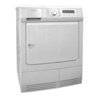
Condenser dryer with heat pump
Brand:
Electrolux
| Category:
Dryer
| Size: 4.88 MB
Table of Contents
Table of Contents
3
1 Introduction
5
Purpose of this Manual
5
Caution
5
Installation
5
2 Technical Characteristics
6
Technical Data
6
Circuit Boards
6
3 Control Panel
7
Stylings
7
Programme Selector
7
Keys
8
Symbols on Models with LCD
9
Child Safety Function
10
Delicate Fabrics (½ Power)
10
Adjusting the Spin Speed
10
DELAYED-START Key - Models with LCD
11
DELAYED-START Key - Models Without LCD
11
Disactivate Buzzer
12
Disactivate Buzzer (Not Only for the Selected Cycle)
12
START / PAUSE Key
12
Adjusting the Level of Conductivity
13
Procedure
13
Display
14
Warning Leds and Symbols
15
4 Operation of the Appliance
16
Operation of a Cycle
16
Operation in PAUSE Mode
16
Operation in DELAYED START Mode
17
Power Failure
17
5 Structural Characteristics
18
Heat Pump in Drying Circuit: Operating Principles
18
Structural Components
20
Drum
21
Air Seal and Drum Spindle Support
21
Hydraulic Circuit
22
Drum Rotation: Principles
22
6 Electrical Components
23
Electronic Control System
23
Main Circuit Board: Functions
23
Electronic Control System Memory: General Structure
24
Conductimetric Sensor
25
Terminal Block with Suppressor
25
Compressor
26
PTC Motor Protector
26
Motor Compressor Capacitor
26
Fan Cooling Compressor
27
Drum Motor
27
Drum Motor Capacitor
27
Canister Fill Pump
28
Air Circulation Fan
28
Fan Motor Capacitor
28
NTC Sensor
29
Door Switch
29
Door Interlock
29
7 Circuit Diagram
30
8 Diagnostics System
31
Access to Diagnostics
31
Exiting the Diagnostics System
32
Selector Positions for Diagnostics (Conductimetric Appliances)
33
9 Alarms
35
Displaying the Last Alarm to the User
35
Displaying Alarms During Normal Operation
35
Reading the Alarms
35
Displaying the Alarms: Models with LCD
35
Displaying the Alarms: Models Without LCD
35
Displaying Other Alarms
36
Cancelling the Last Alarm
36
Notes Concerning Alarm Conditions E93, EH1, EH2 and EH3
36
Table of Alarms
37
10 The Diagnostics Cycle Does Not Start
40
None of the Leds on the Display Board Lights
40
Some of the Leds on the Display Board Light
41
11 Access to Components
42
Door
42
Fluff Filter
42
Fluff Filter on Door
42
Lower Fluff Filter
42
Evaporator Fluff Filter
43
Fluff Filter for Water from Evaporator
43
Compressor for Fan Motor
44
Door Lock
44
Door Microswitch
44
Door Lock Latch - Door Microswitch Latch
45
Drum Light Bulb
45
Canister
45
Work Top
46
Control Panel/Support Assembly
46
Main Circuit Board
47
Removing the Board
47
Removing the Selector Knob Spindle
47
Removing the Selector Knob
47
Key Spring Strip
47
Side Panels
48
Water Ducts
48
Condensation Pump / Float-Actioned Switch
49
Drum Rotation Motor
50
NTC Heat Pump Circuit
50
Drum Brush
51
Rear Brush
51
Rear Air Duct
52
PTC and Motor Overload Cut-Out
52
Dismantling the Chassis for Servicing
53
Air Duct
54
Front Air Seal
54
Idle Pulleys
54
Rear Air Seal
54
12 Checking the Efficiency of the Heat Pump
55
Servicing the Heat Pump Circuit
58
Replacing the Compressor
58
Evacuation
58
Filling
58
13 Door Reversibility
59
Electrolux ENV06 Service Manual (57 pages)
Ventilated, with electronic control
Brand:
Electrolux
| Category:
Dryer
| Size: 3.5 MB
Table of Contents
Tumble Dryer
1
Table of Contents
3
1 Purpose of this Manual
5
2 Warnings
5
Installation
5
3 General Characteristics
6
Circuit Boards
6
4 Control Panel
7
Programme Selector
8
Buttons
8
Symbols on Control Panels with LCD
8
Delicate Programme
9
Cotton and Synthetics Cycles (on Certain Models Only)
10
Long Anti-Crease Cycle (on Certain Models Only)
10
Enabling and Disabling the Buzzer
11
Time Programme (on Certain Models Only)
11
Delay Start
12
Child Lock (on Certain Models Only)
12
START / PAUSE Button
13
Adjusting Conductivity (on Certain Models Only)
14
Adjustment Procedure
14
Indications Displayed
15
End of Cycle
16
5 How to Operate the Appliance
17
How a Cycle Works
17
Operation in PAUSE Mode
17
Opening the Door
18
Power Failure
18
6 Operating Characteristics and Construction
19
Operating Principle
19
Construction
20
Drum
20
Air Seals and Drum Pin Support
21
Drum Rotation Mechanism
21
7 Electrical Components
22
Electronic Control
22
Main Circuit Board Functions
22
Electronic Control Memories: General Structure
23
Conductivity Sensor
25
Junction Box with Integrated Anti-Disturbance Filter
25
Heating Unit
26
NTC Probe
26
Motor Unit
27
Door Lock with Door Microswitch Incorporated
28
Door Lock Without Door Microswitch Incorporated
29
Door Microswitch
29
8 Wiring Diagrams
30
Wiring Diagram for Tumble Dryers with Conductivity Sensor
30
Wiring Diagram for Tumble Dryers with Temperature Probe
31
9 Diagnostic System
32
Accessing Diagnostics
32
Quitting the Diagnostics System
32
Diagnostic Test Phases
33
10 Alarms
35
Displaying User Alarms
35
Viewing Alarms During Normal Operation
35
Reading the Alarms
35
Displaying the Alarm on All Models
35
Viewing any Other Alarms
35
Deleting the Last Alarm
36
Notes on the Behaviour of Certain Alarms
36
11 Alarm Summary Table
37
12 Cannot Access the Diagnostics Programme
39
13 Access to Components
40
Door
40
Door Fastening Latch
40
Door Lock
41
AEG Model Door Lock
41
EMZ Model Door Lock with Fitted Microswitch
41
Door Microswitch Latch (Certain Models Only)
42
Door Microswitch (Certain Models Only)
42
Fluff Filter
43
Drum Lamp
43
Worktop
44
Control Panel
44
Main Circuit Board
45
Removing the Board
45
Removing the Selector Pin
45
Removing the Selector Dial
45
Buttons and Button Springs
45
Back Panel Cover
46
Heating Unit
47
Anti-Disturbance Filter
47
Sides
48
NTC Probe
49
Running Capacitor
49
Motor/Fan Assembly
50
Notes for Reassembly of the Belt Tensioning Roller / Belt
50
Rear Brush (Only on Models with Conductivity Sensor)
51
Front Brush (Only on Models with Conductivity Sensor)
51
Back Panel
52
Belt
53
Drum
53
Conduit Rollers
53
Rear Air Seal
54
Front Air Seal
54
14 Reversing the Door
55
15 Final Testing of Door Fastening
57
Advertisement
Electrolux ENV06 Service Manual (48 pages)
Brand:
Electrolux
| Category:
Washer
| Size: 1.52 MB
Table of Contents
Service Manual
1
Table of Contents
3
1 Purpose of this Manual
4
2 Precautions
4
3 Series 8
5
General Characteristics
5
Control Panel
6
Styling SERIES 8
6
Configuration of Control Panel
7
Programme Selector (S1)
7
Programme Configuration
7
LCD and Buttons
8
4 Demo
14
5 Diagnostic System
15
Access to Diagnostics Mode
15
Exiting Diagnostics Mode
15
Diagnostics Phases
16
Analysis of the LCD Display During the Diagnostic Cycle
17
6 Alarms
18
Displaying the Alarms to the User
18
Reading the Alarm Codes
19
Displaying the Alarm
20
Examples of Alarm Display
20
Operation of Alarms During Diagnostics
20
Rapid Reading of Alarm Codes
21
Cancelling the Last Alarm
21
Cancelling the Memories
22
7 Operating Time Counter
22
8 Washing Programmes and Options
23
Programmes
23
Options
24
Compatibility between Options
26
Descriptions of the Options
27
9 Technical Characteristics
29
Control System Memory
29
General Structure of the Memory System
29
Flash
29
Ram
30
Door Interlock
31
Voltmetric Interlock with PTC
31
Operating Principle
31
Instantaneous Door Interlock
32
Operating Principle
32
Conditions Required for Opening the Door
32
Automatic Unlock
32
Water Fill System
33
Analogue Pressure Switch of Water Level Control in the Tub
33
Drain Pump
34
Recirculation Pump (if Featured)
34
Heating
35
Temperature Sensor
35
Three-Phase Asynchronous Motor
36
Power Supply to Motor
36
Anti-Foam Control System
37
FUCS ( Fast Unbalance Control System)
38
10 Table of Alarm Codes of the Main PCB
40
11 Diagram with THREE-PHASE ASYNCHRONOUS MOTOR
44
12 Accessibility to the Electronic Control System
46
Work Top
46
Control Panel
46
Advertisement
Related Products
Electrolux EN6T4722AF
Electrolux EN7F4722AN
Electrolux EN2F4842BF
Electrolux EN6F5922BF
Electrolux EN2F5842CB
Electrolux EN7F4842OF
Electrolux EN6T5621AF
Electrolux EN6T4722NF
Electrolux EN6T5601AF
Electrolux EN6F5922FB
Electrolux Categories
Refrigerator
Oven
Washer
Dishwasher
Freezer
More Electrolux Manuals
Login
Sign In
OR
Sign in with Facebook
Sign in with Google
Upload manual
Upload from disk
Upload from URL