Sign In
Upload
Manuals
Brands
adept technology Manuals
Control Unit
Python L08
adept technology Python L08 Manuals
Manuals and User Guides for adept technology Python L08. We have
1
adept technology Python L08 manual available for free PDF download: User Manual
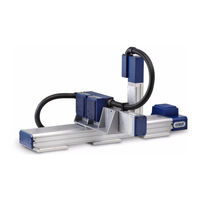
adept technology Python L08 User Manual (172 pages)
Brand:
adept technology
| Category:
Control Unit
| Size: 9.51 MB
Table of Contents
Table of Contents
6
1 Introduction
16
Product Description
16
Adept Python Modules
16
Motionblox-10 Servo Controller and Amplifier
16
Figure 1-1. L18 Linear Module with MB-10 Amplifier
17
Figure 1-2. L12 Linear Module with MB-10 Amplifier
17
Figure 1-3. L08 Linear Module with MB-10 Amplifier
18
Figure 1-4. Three-Axis System with L18, L12, and L08 Modules
18
Special and Custom Orders
19
Adept Smartcontroller CX
19
Figure 1-5. Adept Smartcontroller CX
19
Power Distribution Unit (PDU3)
20
Figure 1-6. PDU3
20
Overview of Typical System Installation
21
Installing Adept Python Modules
21
Installing the Smartcontroller
21
Installing Peripherals and Options
21
Turning on the System
22
Manufacturer's Declaration
22
How Can I Get Help
22
Related Manuals
23
Adept Document Library
23
2 Safety
24
Dangers, Warnings, Cautions, and Notes
24
Intended Use of the Modules
25
Risk Assessment
26
Exposure
26
Severity of Injury
26
Avoidance
27
Control System Behavior Category
27
Precautions and Required Safeguards
28
Maximum Thrust
28
Safety Barriers
29
Impact and Trapping Points
29
Hazards from Expelling a Part or Attached Tooling
29
Additional Safety Information
30
Equipment Modifications
31
Acceptable Modifications
31
Unacceptable Modifications
31
Transport
32
Encoder Battery Life
32
Safety Requirements for Additional Equipment
32
Sound Emissions
33
Thermal Hazard
33
2.10 Working Areas
33
2.11 Qualification of Personnel
34
2.12 Safety Equipment for Operators
34
2.13 Protection against Unauthorized Operation
35
2.14 Safety Aspects While Performing Maintenance
35
2.15 Risks that Cannot be Avoided
35
2.16 Risks Due to Incorrect Installation or Operation
35
2.17 What to Do in an Emergency Situation
36
3 Python Linear Module Descriptions
38
Adept Python Linear Modules
38
Single-Axis and Multiple-Axis Configurations
38
Linear Module Options
38
L-Series Module Types
39
Payloads and Moments
39
Stroke Length
42
Accuracy
42
Ball Screw Lead
43
Speed
43
Acceleration
44
Resolution and Repeatability
44
Thrust
45
Brakes
45
Figure 3-1. L18 Module Without Brake, Shown at End of Stroke
46
Figure 3-2. L18 Module with Brake, Shown at End of Stroke
46
Figure 3-3. L12 Module Without Brake, Shown at End of Stroke
47
Figure 3-4. L12 Module with Brake, Shown at End of Stroke
47
Figure 3-5. L08 Module with Brake (Left) and Without Brake (Right)
47
Motor Mount Configuration
48
Figure 3-6. Left- and Right-Hand Orientation Example
48
Figure 3-7. L18 Module with In-Line Motor
49
Figure 3-8. L18 Module with Left-Side Motor
49
Figure 3-9. L18 Module with Right-Side Motor
50
Figure 3-10. L18 Module with Bottom-Mount Motor
50
Harness Exit Configurations
51
Figure 3-11. In-Line Motor, Left Harness Exit Locations
51
Figure 3-12. In-Line Motor, Right Harness Exit Locations
51
Module Preparation (Assembly)
52
Figure 3-13. Left-Side Motor Mount, Harness Exit Locations
52
Figure 3-14. Right-Side Motor Mount, Harness Exit Locations
52
Cleanroom Modules
53
Module Descriptor Numbers
53
L18 Module Descriptor Number Example and Key
53
Figure 3-15. L18 Descriptor Number Example
53
Figure 3-16. L18 Module Descriptor Key, Part 1 of 2
54
Figure 3-17. L18 Module Descriptor Key, Part 2 of 2
55
L12 Module Options and Descriptor Number Key
56
Figure 3-18. L12 Descriptor Number Key, Part 1 of 2
56
Figure 3-19. L12 Descriptor Number Key, Part 2 of 2
57
L08 Module Options and Descriptor Number Key
58
Figure 3-20. L08 Descriptor Number Key, Part 1 of 2
58
Figure 3-21. L08 Module Descriptor Key, Part 2 of 2
59
Gantry Support Modules
60
Gantry Support Module Descriptor Numbers
60
Figure 3-22. Gantry (LG6) Module
60
Figure 3-23. LG6 (Gantry) Descriptor Number Example
60
Figure 3-24. LG6 (Gantry) Descriptor Number Key
61
4 Python Theta Module Description
62
Adept Python Theta Modules
62
Single-Axis and Multiple-Axis Configurations
62
Theta Module Options
62
L-Series Module Type
62
Gear Ratio
64
Module Preparation (Assembly)
64
Cleanroom Modules
64
Interface
64
Figure 4-1. LT1 (Theta) Module with User Flange
64
Module Descriptor Numbers
65
LT1 Module Descriptor Number Example and Key
65
Figure 4-2. LT1 (Theta) Module with Standard Shaft/Range of Motion
65
Figure 4-3. LT1 (Theta) Module Descriptor Number Example
65
Figure 4-4. LT1 (Theta) Module Descriptor Key
66
5 Module System Descriptions
68
System Configuration Options
68
Module System Descriptor Numbers
68
Module System Descriptor Number Example and Key
69
Figure 5-1. Module System Descriptor Number Example
69
Figure 5-2. Module System Descriptor Number Key, Part 1 of 2
70
Figure 5-3. Module System Descriptor Number Key, Part 2 of 2
71
Control Series
72
Figure 5-4. IO Blox Options in Module System Descriptor Number
72
Figure 5-5. Three-Axis System with MB-10 Amplifiers Identified
72
System Configuration and Module Types
73
Module Types
73
Figure 5-6. Configuration Options in Module System Descriptor Number
73
Single-Axis Configurations
74
System Options
74
Figure 5-7. S2000 System with Mounting Feet
74
Figure 5-8. S2000 System (with Brake) Mounted Vertically
75
Single-Axis Theta Modules
76
Figure 5-9. LT1 (Theta) Module Envelope/Mounting Hole Dimensions (Top View)
76
Figure 5-10. LT1 (Theta) Module Envelope/Mounting Hole Dimensions (Side View)
77
Figure 5-11. LT1 (Theta) Module Envelope/Mounting Hole Dimensions (Bottom View)
77
Figure 5-12. LT1 (Theta) Module User Flange Dimensions
78
Two-Axis Configuration Drawings
79
D Configuration
79
Figure 5-13. D1200 System with Optional Mounting Feet
79
G Configuration
80
Figure 5-14. G1200 System with Optional Mounting Feet
80
K Configuration
81
Figure 5-15. K1200 System
81
Configuration
82
Figure 5-16. X1100 System with Optional Mounting Feet
82
Z Configurations
83
Figure 5-17. Z1200 System
83
Three-Axis Configuration Drawings
84
P Configuration
84
Figure 5-18. P Configuration (P1230 System)
84
Q Configuration
85
Figure 5-19. Q Configuration (Q1230 System)
85
Four-Axis Configuration Drawings
86
P Configuration with Theta
86
Figure 5-20. P Configuration with Theta
86
Q Configuration with Theta
87
System Orientation
87
Figure 5-21. Q Configuration with Theta
87
Figure 5-22. Single-Axis Orientation Example
88
Figure 5-23. Standard/Standard Orientation
88
Single-Axis Orientations
88
Typical Two-Axis Orientations
88
Figure 5-24. Flipped/Standard Orientation
89
Figure 5-25. Standard/Rolled Orientation (Rear View)
89
Figure 5-26. Flipped/Rolled Orientation
90
Mounting Options
91
Figure 5-27. Mounting Options in Module System Descriptor Number
91
Figure 5-28. S1000SS13 - Single L18 System with Three Mounting Feet
92
Figure 5-29. S1000SS00 - Single L18 System Without Mounting Feet
92
Mounting Feet Drawings
92
Figure 5-30. L08 Module with Toe Clamps
93
Figure 5-31. L12 Module with Toe Clamps
93
Toe Clamp Drawings
93
Figure 5-32. L18 Module with Toe Clamps
94
Figure 5-33. L18 Module with Mounting Feet Dimensions
94
Mounting Feet Dimensions
94
Figure 5-34. L12 Module with Mounting Feet Dimensions
95
Figure 5-35. L08 Module with Mounting Feet Dimensions
95
Figure 5-36. LG6 Module with Mounting Feet Dimensions
96
Figure 5-37. L08 Module with Toe Clamp Dimensions
96
Toe Clamp Dimensions
96
Figure 5-38. L12 Module with Toe Clamp Dimensions
97
Figure 5-39. L18 Module with Toe Clamp Dimensions
97
Cable Kits
98
Figure 5-40. Cable Kit Descriptors for a Typical 3-Axis P or Q System
98
Gantry Mounting Kits
99
Figure 5-41. Gantry (LG6) Module Shown with Gantry Mounting Kit
99
Figure 5-42. Gantry Key Details
100
Figure 5-43. L12 Gantry Mounting Methods, End and Side
100
Gantry Support Module Installation
101
Parallel Alignment Specifications
101
Figure 5-44. Gantry Installation: Parallel Alignment Specs
101
Gantry Over-Travel Specifications
102
Figure 5-45. Gantry Installation: Lip Seal to Support Bracket Gap Dimensions
102
Figure 5-46. Gantry Over-Travel Specifications
103
IO Blox
104
Figure 5-47. IO Blox Options in Module System Descriptor Number
105
Figure 5-48. Mounting Onto an MB-10 Amp
105
Figure 5-49. Mounting Onto an L18 Module
106
Figure 5-50. Mounting Onto a Module T-Slot
106
Figure 5-51. Mounting Onto a Two-Axis System
107
Cabling/Plumbing
108
Figure 5-52. Mounting Onto a Three-Axis System
108
Figure 5-53. Cabling/Plumbing Options in Module System Descriptor Number
108
6 Module Installation
110
Lifting and Transporting Modules
110
Mounting Requirements
110
Figure 6-1. Recommended Lifting Technique for Python System
110
Mounting Plate
111
Installing a Python Module System
111
General Installation Notes
111
Figure 6-2. Typical Three-Axis System on Shipping Pallet with Contents Labelled
112
Figure 6-3. Removing Shipping Screws from Axis 3
112
Figure 6-4. Installing Axis 3 on Axis 2
113
Figure 6-5. Removing Shipping Screws from Axis 2
113
Figure 6-6. Removing Shipping Screws from Axis 1
114
Figure 6-7. Lifting a Python System Using a Hoist and Slings
114
Cleanroom System Installation
115
Figure 6-8. Example Cleanroom Module System
116
7 Controller System Installation
118
Installing the Smartcontroller
118
Space Around the Chassis
118
Mounting the Controller Chassis
118
Connect 24 VDC Power and Ground to the Smartcontroller
118
System Cable Diagram
119
Figure 7-1. System Cable Diagram
119
Installing the PDU3
120
Installing the Adept Front Panel
120
Connecting the Optional T2 Pendant to the Controller
120
Installing the User Interface
121
Using Adeptwindows PC Software
121
Graphical Interface Using Adept Desktop
121
Installing Optional IO Blox Units
121
8 Power Distribution Unit
122
Introduction to the PDU3
122
Figure 8-1. Adept PDU3
122
Installing the PDU3
123
Typical AC Power Connection Diagrams for PDU3
124
Figure 8-2. Typical Single-Phase 200-240 VAC Connection
124
Figure 8-3. Typical Three-Phase 200-240 VAC Connection
124
Figure 8-4. Typical Three-Phase 380-415 VAC Connection
124
PDU3 Connectors and Indicators
125
PDU3 Fuses
126
Procedure to Remove Fuse Holder
126
PDU3 Mounting Brackets
127
Figure 8-5. PDU3 with Mounting Brackets Installed
127
PDU3 Dimensions
128
Figure 8-6. PDU3 Dimensions
128
PDU3 Mounting Bracket Dimensions
129
Figure 8-7. Mounting Bracket Dimensions
129
PDU3 Specifications
130
8.10 PDU3 E-Stop Circuit Diagram
131
Figure 8-8. E-Stop Circuit Diagram for PDU3
131
8.11 PDU3 Connector Specifications
132
XDCS Connector
132
XSLV1/2 Connector
132
9 Adept MB-10 Amps
134
Overview
134
Figure 9-1. Adept MB-10 Amplifier
134
Operation
135
Status Panel
135
Indicator LED
136
Brake Release Button
136
MB-10 Connectors
136
Figure 9-2. Connector Locations on MB-10 Amp
136
IO Blox Connector
137
Figure 9-3. Attaching the AC Power and Ground Cables
137
EEPROM on MB-10 T-Bracket
138
MB-10 Firmware
138
Figure 9-4. EEPROM Device on T-Bracket
138
Specifications
139
Connector Specifications
140
10 System Operation
144
10.1 Introduction
144
10.2 Verifying Installation
144
Mechanical Checks
144
Power Checks
145
Cable Installation Checks
145
User-Supplied Safety Equipment Checks
145
10.3 Turning on Power
146
10.4 Software Configuration
146
Load and Run DC_SETUP.V2
147
Figure 10-1. DC_SETUP Program Main Screen
147
Figure 10-2. DC_SETUP Program Setup Screen
148
Figure 10-3. DC_SETUP Program Node to Robot/Motor Map Screen
148
Figure 10-4. DC_SETUP Program Current Configuration Screen
149
Run Module Calibration Setup Program
150
Figure 10-5. Calibration Setup Screen
150
Adaptive Feed-Forward Compensation
151
10.5 Enable High Power
151
10.6 Run-Time Calibration
152
10.7 Turning off Power
152
Operating and Programming an Adept Python Modules System
152
11 Maintenance
154
11.1 Introduction
154
11.2 Checking Safety Systems
155
Every Six Months
155
11.3 Replacing the MB-10 Internal Battery
155
Battery Replacement Time Periods
155
Battery Replacement Procedure
156
Figure 11-1. MB-10 Internal Battery and Retaining Clip
156
11.4 Replacing the Module Encoder Battery
157
Figure 11-2. MB-10 Internal Battery Location
157
Figure 11-3. Encoder Battery
157
Battery Replacement Procedures
158
Battery Accessible Via End Cap Removal
158
Battery Not Easily Accessible, MB-10 Removal Required
159
Figure 11-4. Replacement Cable Assembly Installed in Module
159
Battery Replacement Time Periods
158
11.5 Python Module Maintenance
160
11.6 Additional Maintenance
160
11.7 MB-10 Decommissioning
160
12 Advanced System Configurations
162
12.1 Description
162
Figure 12-1. System Installation with Two Linear Module Robots Daisy-Chained
163
Figure 12-2. System Installation with Three Linear Module Robots and Two Pdus
164
Figure 12-3. Three Linear Module Robots, Two Pdus, and a Cobra S600 with Vision
165
Index
166
Advertisement
Advertisement
Related Products
adept technology Python L18
adept technology Python L12
adept technology Python LT1
adept technology Python
adept technology Lynx Platform
adept technology R Series
adept technology R-H
adept technology R-Hz
adept technology R-M
adept technology R-Mz
adept technology Categories
Robotics
Controller
Network Router
Thermostat
Control Unit
More adept technology Manuals
Login
Sign In
OR
Sign in with Facebook
Sign in with Google
Upload manual
Upload from disk
Upload from URL