Table of Contents
Advertisement
Quick Links
Advertisement
Table of Contents

Related Manuals for Ko Propo EX-1


Summary of Contents for Ko Propo EX-1
-
Page 2: Table Of Contents
■ Table of Contents Click the page number to jump to that page. Title Title Page Page ■ Table of Contents 3CH/4CH Menu(3/4ch Menu) ■ For Safe Operation Control Menu(Control Menu) ■ Getting Started Control Mode(Control Mode) ●Transmitter Assembly 2WAY(2WAY) ●Transmitter Dismantling 3WAY(3WAY) ■... -
Page 3: For Safe Operation
■ For Safe Operation... -
Page 5: Getting Started
■ Getting Started [Legend] :Point :Notice ●Transmitter Assembly ●Transmitter Dismantling Insert the Grip Unit into the Master Unit, then attach the Detach the Steering Unit, then detach the Master Unit. Steering Unit. Steering Unit Remove the connector cover before attaching. Master Unit First detach the antenna. -
Page 6: Names Of Parts
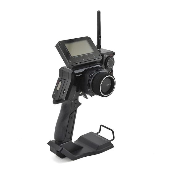
■ Names of Parts [Side View] [Front View] Antenna Tilt Display Direct Button DBT 1-4 (p.7) Jog Dial Steering Wheel (p.7) (p.7) Multicolor LED Dial Guard (p.7) (p.7) Enter Key (p.7) Back Key (p.7) Power Switch (p.8) Trigger Guard Steering Unit Steering Unit (p.7) Release Button... -
Page 7: Et Keys (1-5) And Bt Button
PC. It also enables numerous model memory settings to be saved onto a PC. Refer to KO Propo's website for details on how to use this feature. ( http://www.kopropo.co.jp/sys/ ) Excessive counterclockwise rotation will result in the wheel being unable to return to neutral position. -
Page 8: Colored Grip And Pad Replacement
If storing the transmitter in dismantled form, please remember to attach the connector covers. After prolonged use, a black residue may build up on the connectors. Use cotton swabs dipped in cleaning alcohol to remove. KO Propo's Customer Service Department also handles transmitter maintenance. -
Page 9: Preparations
●Battery Pack (Under Development) Battery Box A rechargeable battery pack specific to the EX-1 is under development. An announcement will be made on the KO Use batteries which have adequate remaining capacity. Weak Propo website when it is ready for release. Thank you for your batteries mean lower transmitting power and may result in patience. -
Page 10: Countermeasures Against Noise
●Countermeasures Against Noise... -
Page 11: Receiver Installation
In this case, move some distance away or wait a while For items which are not included in this product, please refer to the before attempting the pairing procedure again. KO Propo website for a list of compatible products. (http://www. kopropo.co.jp) -
Page 12: Fail Safe Setting
●Fail-Safe Setting Please be sure to set the fail-safe. Fail-safe is when the receiver loses the radio signal of the transmitter If you change the position of the fail-safe operation, please set and the function keeps channel 2 (throttle) in an optional position. again. -
Page 13: Procedures Prior To Operation
■ Procedures Prior to Operation 1.Switching On After ensuring that it is safe to do so, switch on the transmitter followed by the receiver. This product uses the FHSS transmission system, which switches between frequencies in the2.4GHz range at a high speed. FRANCE Mode needs to be selected if this product is to be used in France, while other countries should use GENERAL Mode. -
Page 14: Trim And Sub Trim Operation
●Trim and Sub Trim Operation The sub trim is a convenient feature but it could also complicate the setting process if used incorrectly. Use the sub trim in the correct manner while also referring to the sub trim operation instructions on p.21 and p.26. [Purpose of the Trim] When a servo is to be mounted onto a model, it is usually connected to the ●Trim (Center Trim) -
Page 15: Display And Control Method
■ Display and Control Method ●Basic Operations to Change Settings Control of setting adjustments is done via the Jog Dial, ENTER key, and BACK key. Used to move cursor between menu choices and change setting values. Jog Dial: Clockwise Rotation:Raising value (for L/R cases: raising toward R); Proceed to next item Counterclockwise Rotation:Lowering value (for L/R cases: raising toward L);... -
Page 16: Startup Screen And Initial Screen
●Startup Screen and Initial Screen When the transmitter is switched on, the startup screen will display, followed by the initial screen. Pressing the ENTER key during the startup screen will allow you to proceed to the initial screen. Startup Screen Version Information: Displays the version of the program that is installed in the Master Unit's CPU. -
Page 17: Function Reference
■Function Reference [Legend] :Operating Procedure :Point :Notice (see p.15 for basic operation) ●Main Menu This an index which displays the 8 different function menus. To Model Menu(Model) switch between function menus, use the direct keys or do so via the main menu. (If you wish to use the direct keys, they must Save various settings as model memories Up to 40 model memories can be named and stored. -
Page 18: Model Select(Mdl-Select)
Model Select(MDL-Select) Model Name(MDL-Name) Switch between different model memories. This function is used to name the model memory that is currently in use. Distinguish each model memory with different Example names, which may also be edited. The set model name will be If you have multiple cars, it is convenient to have a separate displayed on the initial screen and model select screen. -
Page 19: Model Copy(Mdl-Copy)
Model Copy(MDL-Copy) Model Reset(MDL-Reset) Copies the current model memory to a different model memory. Return the current model memory to default setting values. Example When changing settings on the same car to match driving conditions, it is convenient to copy the original memory before modifying it. -
Page 20: Steering Menu(Steering)
Steering Menu(Steering) Steering Trim(ST-Trim) Settings related to steering control. Adjusts the neutral/center position of the steering angle range. Also refer to Trim and Sub Trim Operation.(p.14) [Functions] Steering Trim Modify the neutral position of the steering angle. (N:Neutral L:Left R:Right) Steering Travel Modify the overall amount of steering movement. -
Page 21: Steering Balance(St-Balance)
Steering Balance(ST-Balance) Steering Sub Trim(ST-SubTrim) Adjust the left/right steering angles independently. This enables Adjust the position of the overall steering angle range. Use this the turning radii to match up during cornering. to match the neutral position when installing the steering servo. Also refer to Trim and Sub Trim Operation.(p.14) (N:Neutral L:Left R:Right) Example... -
Page 22: Steering Turn Speed(Turnspeed)
Steering Turn Speed(TurnSpeed) Steering Return Speed(RetnSpeed) This function limits the maximum speed of the steering servo This function limits the maximum speed of the steering servo by adjusting the steering turn direction [TURN] setting. The by adjusting the steering return direction [RETURN] setting. steering angle between neutral and full lock is split into two The steering angle between neutral and full lock is split into two zones and each may be adjusted independently (2WAY). -
Page 23: Steering Curve(St-Curve)
Steering Curve(ST-Curve) Steering Punch(ST-Punch) This function quickens the steering's initial response and can This function adjusts the ratio of the steering angle to servo be used to instill a strong turning movement when the steering movement speed (Curve Characteristics). Choose between (+) Quick Curve and (-) Mild Curve. -
Page 24: Steering Punch(St-Punch)
Steering Reverse(ST-Reverse) Travel Override(Travel Override) Adjust the steering angle according to the driving conditions to This function reverses the steering direction. This setting screen make the car easier to control. is common with the throttle. Example Example Use this function when, after installing the servo, movements Convenient for changing the steering angle on straights to give are the opposite of transmitter inputs (turning the steering wheel the car better straight-line stability. -
Page 25: Throttle Menu(Throttle)
Throttle Menu(Throttle) Throttle Trim(TH-Trim) Settings related to throttle control. Adjusts the neutral/center position of the throttle range. Also refer to Trim and Sub Trim Operation. (p.14) [Functions] Throttle Trim (N:Neutral F:Forward B:Brake) Modify the neutral position of the throttle. Throttle High Point Modify the maximum amount of throttle movement (towards forward acceleration). -
Page 26: Throttle Brake(Th-Brake)
Throttle Trim Rate(TH-TrimRate) Throttle Brake(TH-Brake) Adjust the maximum amount of brake movement. Adjusts the amount of movement associated with one click of the throttle trim button. This setting screen is common with the steering. (N:Neutral F:Forward B:Brake) High Point Brake Position Setting Range Setting Range 0 - 150(... -
Page 27: Throttle Turn Speed(Th-Turnspeed)
Turn Speed may be set to be divided into two zones (2WAY) or Throttle Turn Speed(TH-TurnSpeed) have no divisions at all (1WAY). [Changing to 2WAY] This function delays the conversion of the throttle control signal Changing the two [TURNPOS] to the same value will deactivate to make the car easier to control. -
Page 28: Throttle Return Speed(Th-Returnspeed)
Return Speed may be set to be divided into two zones (2WAY) or Throttle Return Speed(TH-ReturnSpeed) have no divisions at all (1WAY). [Changing to 2WAY] This function delays the conversion of the throttle control signal Changing the two [RETNPOS] to the same value will deactivate to make the car easier to control. -
Page 29: Throttle Punch(Th-Punch)
Throttle Curve(TH-Curve) Throttle Punch(TH-Punch) This function quickens the throttle's initial response and can be This function sets the signal conversion rate to a curve to used to instill a sense of power when the throttle initially moves enable quicker or milder response. Likewise, braking can also be set to a braking curve. -
Page 30: Throttle Reverse(Th-Reverce)
Throttle Reverse(TH-Reverce) Brake Override(Brake Override) This function reverses the throttle direction. This setting screen Arrange another maximum brake setting, which can be activated/deactivated by the ET lever or BT button. is common with the steering. Example Use this function when, after installing the servo, movements are Example the opposite of transmitter inputs (pulling the trigger to accelerate If a change in driving conditions is foreseen, the throttle brake... -
Page 31: Throttle Abs(Th-Abs)
Throttle ABS(TH-ABS) [Regarding WIDTH and TRG.P] Setting [WIDTH] to 0 will deactivate ABS. To prevent tires from locking up during sudden braking, brake The amount of ABS applied by the servo is determined by the pumping will be applied. amount of throttle trigger movement as well as the [WIDTH] and [TRG.P] setting values. -
Page 32: Throttle Acceleration(Th-Accel)
Throttle Acceleration(TH-Accel) [Regarding WIDTH] Setting [WIDTH] to 0 will deactivate ABS. Just like professional drivers who are capable of precise throttle inputs, this function enables fine throttle adjustments to allow [Regarding TRG.L and TRG.H] quicker cornering. Throttle feathering will occur when the throttle trigger is moved to the positions set by [TRG.L] and [TRG.H]. -
Page 33: Throttle Auto-Start(Th-Autostart)
Throttle Auto-Start(TH-AutoStart) Idle Up(IdleUp) This function sets the throttle output to a fixed level at startup, Used to offset the throttle's neutral position. regardless of how much the throttle trigger is pulled. Example Raising the idling has the effect of improving a glow engine car's launch performance. -
Page 34: 3Ch/4Ch Menu(3/4Ch Menu)
3CH/4CH Menu(3/4ch Menu) Control Mode(Control Mode) 3Settings related to 3CH and 4CH operations. Set the usage choice for channels 3 and 4. (In order to operate 3CH and 4CH, the response function's OUTPUT setting must be changed from 2CH to 4CH.) [Functions] 3CH Control Menu Adjusts settings related to 3CH. -
Page 35: 3Way(3Way)
5WAY(5WAY) 3WAY(3WAY) Modify the 3-interval output settings. Modify the 5-interval output settings. Example Example May be used for gear changing operations or when you wish to May be used for gear changing operations or when you wish to set a 3-interval control scheme for the servo. set a 5-interval control scheme for the servo. -
Page 36: Analog(Analog)
ANALOG(ANALOG) These settings are to enable continuous output for channels 3 or 4. CCEN Position (white square) LLOW Position (black square) HHIGH Position (black square) Setting Range KEY:OFF, ET1 - 5, BT1( :OFF) Default Assigns a key to use for switching positions. REVERSE:NOR , REV :NOR) -
Page 37: 4Ws Mixing(4Wsmix)
4WS Mixing(4WSMix) 4WS Mixing Left(4WSMix LEFT) This function is related to an R/C car's 4-wheel steering feature. Adjusts the rear axle servo movement range when steering is If 3CH or 4CH is assigned to control the rear axle, it will operate turned to the left. -
Page 38: 4Ws Mixing Right(4Wsmix Right)
4WS Mixing Right(4WSMix RIGHT) 4WS Mixing Reverse(4WSMix REVERCE) Adjusts the rear axle servo movement range when steering is This function reverses the rear axle's movement direction. turned to the right. Equivalent to (Balance R) in the [Steering Balance] function. Setting Range , REV :NOR) (Normal) -
Page 39: Amp Mixing(Amp Mix)
Amp Mixing Mode(AMPMix MODE) Amp Mixing(AMP Mix) Used when the front and rear wheels are controlled by separate Choose from five 4-wheel drive modes. ESCs and motors. If 3CH or 4CH is set to the front-wheel drive function, it will operate in conjunction with 2CH's throttle operations. -
Page 40: Amp Mixing Throttle Hold(Ampmix Hold)
Amp Mixing Throttle Amp Mixing High Point Hold(AMPMix HOLD) (AMPMix HIPOINT) This function adjusts the set speed used for (F HOLD) and (R Adjusts the maximum amount of throttle to be applied to the HOLD) selected in Amp Mixing Mode. front wheels. -
Page 41: Amp Mixing Reverse(Ampmix Reverse)
Amp Mixing Reverse Amp Mixing ET Mode Setting (AMPMix REVERSE) (AMPMix ET MODE SET) Changes the movement direction of the front wheels. Assigns ET or BT keys to activate the various front wheel drive modes. Setting Range Setting Range :OFF) Default , REV :NOR) -
Page 42: Throttle Mixing(T-Mix)
Throttle Mixing Brake(T-Mix BRAKE) Throttle Mixing(T-Mix) Mainly used for 1/5 scale R/C cars where the left/right front Adjusts the maximum amount of front brake servo movement. wheels' braking operation is controlled by an independent servo. If 3CH is assigned to front right wheel brake and 4CH is assigned to front left wheel brake, they will operate in conjunction with 2CH (throttle) and 1CH (steering). -
Page 43: Throttle Mixing High Point(T-Mix Hipoint)
Throttle Mixing High Point Throttle Mixing Curve(T-Mix CURVE) (T-Mix HIPOINT) This function sets the signal conversion rate to a curve to enable quicker or milder response. Adjust the maximum amount of throttle to be applied to the front brake servo. (N:Neutral F:Forward B:Brake) If 3CH and 4CH are assigned to the brake servo, the value will be set to 0. -
Page 44: Throttle Mixing Steering(T-Mix Steer)
Throttle Mixing Steering(T-Mix STEER) Throttle Mixing Key(T-Mix KEY) Assigns ET keys to be used for Throttle Mixing. Full braking can be weakened or made even stronger in accordance with steering input. Example When a 1/5 scale R/C car is driven for a long duration, loss of front tire grip would lead to understeer. -
Page 45: Quick Setup(Quicksetup)
Quick Setup(QuickSetup) By following the menu in order, this function enables creation of a basic initial setup. Example Useful for setting up a car for the first time. It is recommended for users to use quick setup first, then make fine adjustments to match the driving conditions. -
Page 46: Timer Menu(Timer Menu)
How to Use the Various Alarms Timer Menu(Timer Menu) Operating Timer-related functions. [Functions] Stopwatch This may be used to keep track of elapsed time. It also has a lap navigation function. Countdown Timer A timer which counts down the time. Lap History How to Start Stopwatch Displays the lap times recorded by the stopwatch. -
Page 47: Countdown Timer(Downtimer)
Countdown Timer(DownTimer) Lap History(LapHistory) A timer which counts down from a set time. Displays the lap times recorded by the stopwatch. Example (TTL:Total Time) Useful to tracking the refueling timing for a glow engine car. (m:minutes s:seconds) Use the jog dial to scroll. (Basic Operation p.15 ) Up to 6 lap times can be displayed at one time. -
Page 48: Function Menu(Function Menu)
Function Menu(Function Menu) LED Color(LEDcolor) Menu related to various function settings. Select the color of the backlight for the EX-1 logo on the Master Unit. Choose to set it at one of seven colors, or disable [Functions] it altogether. Monitor Display the operations of each channel as a graphical representation. -
Page 49: Lcd Contrast(Contrast)
LCD Contrast(Contrast) Buzzer(Buzzer) Adjusts the contrast of the LCD. Sets the transmitter buzzer type. Select the desired choice. Adjust the slide bar. (Basic Operation p.15) (Basic Operation p.15) Setting Range 5 intervals( Setting Range OFF, 7 types ( Default Default LCD contrast will characteristically be darker when warm and lighter when cold. -
Page 50: System Menu(System Menu)
Select the response mode to match your servo, ESC, etc. It may also be used to adjust cornering response, etc. [Functions] Please refer to the KO Propo website for a list of compatible products. (http://www.kopropo.co.jp) Response Select a response mode according to the equipment installed or driving conditions. -
Page 51: Setup(Setup)
Default VR Adjust timing may vary depending on usage. If problems persist ET1(S:TRIM) ET2(T:TRIM) ET3(T:BREAK) even after using VR Adjust, contact KO Propo Customer Service ET4(S:TRAVEL) ET5(OFF) BT1(OFF) Department to arrange repairs. (We recommend that you contact KO Propo Customer Service Department if you are not sure what the... -
Page 52: Adjust Vr (Th)(Throttleajustvr)
Setting Range :GENERAL) VR Adjust timing may vary depending on usage. If problems persist Default even after using VR Adjust, contact KO Propo Customer Service GENERAL , FRANCE (Normal Mode) (France Mode) Department to arrange repairs. -
Page 53: Power Management(Power Management)
Power Management(POWER ICS(ICS) MANAGEMENT) Connect transmitter to a PC with ICS. Select the type of battery used. Example Use when you wish to adjust the transmitter's data with a PC. Select the appropriate choice. (Basic Operation p.15) Setting Range Select [YES] (press and hold ENTER key) to connect ICS. (Basic , NI-MH (Alkaline Batteries) -
Page 54: Warning Display
●Warning Display Battery Level Warning During startup, this warning will be displayed if the battery voltage is below the required level. Normal operation will not be able to continue. During driving, this warning will be displayed if the battery voltage is below the required level. You may still operate the model, but it is recommended to replace the battery immediately. -
Page 55: Glossary
■ Glossary This section explains terms which appear in this instruction manual as well as terms which are common in the radio control hobby. -
Page 58: Specifications
■ Specifications...
Need help?
Do you have a question about the EX-1 and is the answer not in the manual?
Questions and answers