Table of Contents
Advertisement
Advertisement
Table of Contents

Related Manuals for Ko Propo EX-2


Summary of Contents for Ko Propo EX-2
- Page 1 INSTRUCTION MANUAL KONDO KAGAKU Co., Ltd. 2015 Ver.1.0...
-
Page 2: Table Of Contents
■ Table of Contents ※ Click the page number to jump to that page. Title Title Page Page ■ Table of Contents ▶KEYSPEED ■ For Safe Operation ▶OPERATIN ALARM ■ Getting Started □■□ STEERING MENU ●Transmitter Assembly ●TRAVEL MENU ●Transmitter Dismantling ▶ST TRAVEL Steering Travel ■... -
Page 3: For Safe Operation
Due to the nature of radio controlled models, improper handling may lead to dangerous situations. Therefore please read the following information carefully in order to ensure safe operation. Please also understand that KO Propo is not responsible for any injuries or damage which result from noncompliance of these cautions and notices. - Page 4 Follow the reverse order when switching off. ※If the wrong order is followed, it may lead to an uncontrollable model. ●Dismantling or modifying the RF Module (internalized in the case of the EX-2) is Caution! prohibited and is punishable by law.
-
Page 5: Getting Started
■ Getting Started [Legend] :Point :Notice ● Transmitter Assembly ● Transmitter Dismantling Insert the Grip Unit into the Master Unit, then attach Detach the Steering Unit, then detach the Master the Steering Unit. Unit. Steering Unit Remove the connector cover before use. Master Unit ③... -
Page 6: Names Of Parts
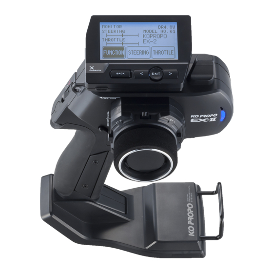
The possible functions which each key/ button may be assigned to are different. ※ Only Expert grip unit available.(No.10526) There is no ET4/5 keys in the following sets. No. 80561 EX-2 Standard Edition (p.7) Colored Pad Guard Bar 《Rear View》... -
Page 7: Et Keys (1-5) And Bt Button
● ET Keys (1-5) and BT Button (1) ● Throttle Trigger Position Adjustment Functions may be assigned to the keys/button. The position of the throttle trigger may be adjusted to match the user's hands. The possible functions which each key/button may be [How to Adjust] assigned to are different. -
Page 8: Unit Connector
Begin charging using a current of less than 1A. storing the transmitter in dismantled form. After prolonged use, a black residue may build up on the connectors. Use cotton swabs dipped in cleaning alcohol to remove. KO Propo's Customer Service Department also handles transmitter maintenance. ● Power Switch This product features a safety lock. -
Page 9: Preparations
■ Preparations ● Battery Installation ● Battery Level Warning A warning will be displayed with the LED flashing and Press the tab on the bottom of the transmitter to open an alarm will sound when battery voltage is less 4v. battery box cover. -
Page 10: How To Change The Modulation
① Turn off EX-2 switch. ② Push the ET1 lever to the left and power on. ③ Hold ET1 lever until the buzzer sounds and the LED of EX-2 turns on (approximately two seconds). PowerON Approximately two seconds, LED turns on. -
Page 11: Countermeasures Against Noise
● Countermeasures Against Noise Keep antenna cable away from all sources of noise! Noise is generated in any area where a large amount of Carbon Fiber Chassis Battery Pack electric current is flowing. Position the receiver and antenna cable as far away from the motor, battery, ESC, and their associated cables as possible. -
Page 12: Receiver Installation
This transmitter is only compatible with digital servos. Correct operation is not possible when used with analog servos. For items which are not included in this product, please refer to the KO Propo website for a list of compatible products. (http://www.kopropo.co.jp) -
Page 13: Fail-Safe Setting
● Fail-Safe Setting Fail-safe is when the receiver loses the radio signal Please be sure to set the fail-safe. of the transmitter and the function keeps channel 2 (throttle) in an optional position. The configuration is usually full brake or neutral. If you change the position of the fail-safe operation, please set again. -
Page 14: Procedures Prior To Operation
■ Procedures Prior to Operation 1.Switching On After ensuring that it is safe to do so, switch on the transmitter followed by the receiver or Mini-Z. 2.Model Confirmation Confirm the model which will be used. 3.Checking Movements ... -
Page 15: Trim And Sub Trim Operation
● Trim and Sub Trim Operation The sub trim is a convenient feature but it could also complicate the setting process if used incorrectly. Use the sub trim in the correct manner while also referring to the sub trim operation instructions on p.39 and p.44. 《Purpose of the Sub Trim》... -
Page 16: Display And Control Method For Attaching The Xpansion Unit
■ Display and Control Method for attaching the Xpansion unit ● Basic Operations to Change Settings Controlling of the setting adjustments is done via the L(<) key, R(>)key, Operation ENTER(ENT) key, and BACK key. ENT Key: Selecting item to be modified; Confirming a change after a setting change. L(... -
Page 17: Installation Of Xpansion Unit
③ Attach expansion unit to a master unit. and front positions. While matching the edge of the base with When assembling or disassembling the Xpansion unit to the dent of the bracket, slide it until the EX-2, please switch off the EX-2. Xpansion unit locks. -
Page 18: Startup Screen And Initial Screen
Version Information : Displays the version of the program that is installed in the Master Unit's CPU. This product's performance may be upgraded via paid or free upgrades. Check the KO Propo website for information regarding such upgrades. ( http://www.kopropo.co.jp ) ①... -
Page 19: Vr Information Setting
※ When disassembling the Xpansion unit, this configuration to calibrate your system. operation is the same. ○ When using EX-2 for the first time. 《Functions》 ○ When changing a steering unit for a different product or when putting it back together. -
Page 20: Pairing (For General Receiver)
For items which are not included in this product, please ③ Check that the receiver's LED refer to the KO Propo website for a list of compatible lights up again (indicating products. (http://www.kopropo.co.jp) pairing completion) Lit LED... -
Page 21: Pairing (For Mhs Mini-Z)
In order for the receiver to operate, it must store the Preparing the Mini-Z transmitter's unique ID in its memory in a process ① Bring distance of EX-2 and MiniZ close to about called “pairing.” Even if a single transmitter is used 10cm. -
Page 22: Top Menu
■ TOP MENU FUNCTION STEERING This an index which displays the 6 different function This an index which displays the 6 different function menus. menus. Model Menu (MODEL) Steering Travel Operations such as selecting or copying a model. Modify the overall amount of steering movement. -
Page 23: Throttle Trim
THROTTLE This an index which displays the 10 different function menus.(Separeted 2 pages.) Throttle Travel MENU1 Modify the maximum throttle movement. Jump menu to throttle menu 1. Throttle Trim Brake Override Modify the neutral position of the throttle. Modify the maximum amount of braking and steering travel assigned to a switch. -
Page 24: Function
FUNCTION Model menu Save various settings as model memories Up to 20 ▶ MODEL NAME model memories can be named and stored. This function is used to name the model memory that MODEL モデル is currently in use. Distinguish each model memory with different names, which may also be edited. -
Page 25: Model Copy (Mdl-Copy)
MODEL ▶ MODEL COPY ▶ MODEL RESET Copies the current model memory to a different model Return the current model memory to default factory memory. setting values. 【Example】 Select [RESET] (hold ENTER key) to reset. When changing settings on the same car to match driving conditions, it is convenient to copy the original memory before modifying it. -
Page 26: Timer Menu
TIMER Menu Operating Timer-related functions. 100 lap times are memorized. 《Functions》 ▶ TRGSTART Trigger Start Only the last recorded lap times may be checked and previously recorded results will not be saved. Prepares the stopwatch for activation via the throttle movement. (Even if the transmitter is switched off, the last ▶... -
Page 27: Keyset (Key Setting Menu)
KEYSET Key setting Assign a key (ET1- ET5, BT1) to a function. B T 1 If you select a key, the item is displayed to the right. It is assigned to a key by choosing an item. KEYSET キーセッテイ 1:S:TRIM ※ To use (ET4, ET5), No,10526 Expert grip is required. ET 2:T:... -
Page 28: 3・4Ch (3・4Channel)
3・4CH 3・4ch Menu Settings related to 3CH and 4CH operations. 【Setting Range】 START:POS 1、POS 2(Default:POS 1) Sets the starting position. KEY:OFF、ET1 〜 5(Default:OFF) Assigns a key to use for switching positions. POS 1:-100 〜 100(Default:0) Sets Position 1's output position. POS 2:-100 〜 100(Default:100) Sets Position 2's output position. -
Page 29: 5Way(5Way
3・4CH 3・4ch Menu :-100 〜 0(Default:-100) ▶ 5WAY MODE (Low Position) Sets the lowest value for the operation range. :LOW 〜 HIGH(Default:0) Modify the 5-interval output settings. (Center Position) Sets the neutral position for the operation range. 【Example】 May be used for gear changing operations or when HIGH :0 〜... -
Page 30: Twin Servo (Twin Servo Mixing Menu)
3・4CH 3・4ch Menu ▶ TWIN SERVO MODE ▶ 4WS This function modifies the setting for using 2 steering This function is related to an R/C car's 4-wheel servo. Using left steering servo 1ch, and right steering steering feature. If 3CH or 4CH is assigned to control servo 3ch or 4ch. -
Page 31: Amp (Amp Mixing Menu)
3・4CH 3・4ch Menu ▶ AMP Mixing MODE On glow engine cars, an overly high setting value will Used when the front and rear wheels are controlled increase load on the servo and lead to it being damaged. by separate ESCs and motors. If 3CH or 4CH is set Check carefully while adjusting. -
Page 32: T-Mix (Throttle Mixing Menu)
3・4CH 3・4ch Menu ▶ T-MIX Throttle Mixing MODE Mainly used for 1/5 scale R/C cars where the left/ 3CH MODE : T-MIX right front wheels' braking operation is controlled by an independent servo. FOWARD CURVE: If 3CH is assigned to front right wheel brake and 4CH BRAKE CURVE: is assigned to front left wheel brake, they will operate in conjunction with 2CH (throttle) and 1CH (steering). -
Page 33: Trim Set (Trim Set Menu)
TRIM SET The convenient function that can set trim and travel ▶ STEER AUTO BALANCE LEFT while operating steering wheels. ① Move the cursor to "SET" and push the ENT key, "SET" will start blinking. ※ At this time, the steering travel(L) becomes 100 forcibly. -
Page 34: System Menu
SYSTEM MENU Menu related to various system settings. ▶ BATTERY Select the type of battery used. BATTERY バッテリー LIFe カンデンチ リフェ NI-MH LIPO ニッケル リポ 【Setting Range】 DRY(Alkaline Batteries), Primary warning buzzer 4.0V or less Second warning buzzer, movement stop 3.8V or less LIFE(Li-Fe Battery) Primary warning buzzer 6.2V or less Second warning buzzer, movement stop 6.0V or less... -
Page 35: Warning ! Warning Display
Y o u m a y s t i l l o p e r a t e t h e m o d e l , b u t i t i s recommended to replace the battery immediately ※ In the case of DRY/Ni-MH setting, the LED (blue) of the main body of EX-2 flashes on and off, too. BATTERY WARNING LOW VOLTAGE EXIT >>... -
Page 36: Calculator
※ Please set it by all means. Do not operate steering wheel and throttle trigger while ○ When using EX-2 for the first time. pressing ENTER, as this may change the data values ○ When changing a steering unit for a different and affect subsequent operations. -
Page 37: Keyspeed
▶ OPERATION ALARM When there is no input to the transmitter in over three minutes, the EX-2 alarm will sound. The alarm is canceled when operating steering wheel, throttle trigger, ET, BT key, ENT key, L R key, BACK key. -
Page 38: St Travel Steering Travel
STEERING TRAVEL Modify the overall amount of steering movement. ▶ ST BALANCE L R Steering BalanceL R Adjust the left/right steering angles independently. This enables the turning radii to match up during cornering. 【Setting Range】 ST BALANCE L : 30 〜 100 (Default : 70)... -
Page 39: Trim Menu
TRIM MENU Adjusts the neutral/center position of the steering ▶ ST SUBTRIM angle range. Adjust the position of the overall steering angle range. Use this to match the neutral position when installing the steering servo. ※ Also refer to Trim and Sub Trim Operation.(p.15) 【Setting Range】... -
Page 40: St Speed Steering Speed
ST SPEED Steering SPEED Modify the speed of the steering servo movement. ▶ ST TURN Steering Turn Speed This function limits the maximum speed of the steering servo by adjusting the steering turn direction [TURN] setting. 【Setting Range】 ST TURN SPEED : 1 〜 100% (Default : 100%)... -
Page 41: Dynamc Steering Dynamics
DYNAMC Steering Dynamics Settings related to steering control. ST DYNAMICS ダイナミクス CURVE カーブ Steering Movement PUNCH パンチ 0 ▶ CURVE Steering Curve Modify the movement speed ratio which corresponds to ▶ PUNCH Steering Punch steering angle. ▶ PUNCH Steering Punch This function quickens the steering's initial response ... -
Page 42: St Feel Steering Feel Menu
FEEL Steering feel MENU REVERSE Steering Reverse FEEL function provides changing the moving Modify the steering direction. peformance of steering servo. FEEL フィール REVERSE リバース ST FEEL ST REVERSE ステアリングフィール NORM ステアリングリバース TH FEEL TH REVERSE スロットル フィール スロットル リバース NORM ▶ ST FEEL Steering Feeling ▶... -
Page 43: Travel Throttle Travel
THROTTLE TRAVEL Throttle Travel Settings related to throttle control. ▶ TH TRAVEL B Throttle Travel B Adjust the maximum amount of brake movement. 【Setting Range】 TH TRAVEL B : 0 〜 150 (Default : 100) The key setting displays [T:BRAKE]. On glow engine cars, an overly high setting value will increase load on the servo and lead to it being damaged. -
Page 44: Th Trim Throttle Trim
TRIM Throttle Trim Settings related to throttle control. ▶ TH SUBTRIM Throttle Subtrim Adjust the position of the overall throttle movement range. Use this function when the neutral position cannot be centered with only linkage adjustment.Also refer to Trim and Sub Trim Operation. (p.15) 【Setting Range】... -
Page 45: Th Speed Throttle Speed
TH SPEED Throttle Speed Settings related to throttle control. ▶ TH TURN Throttle Turn Speed This function delays the conversion of the throttle control signal to make the car easier to control. 【Setting Range】 TH TURN SPEED : 1 〜 100% (Default : 100%) 【Example】... -
Page 46: Dynamc Throttle Dynamics
DYNAMC Throttle Dynamics Settings related to throttle control. Quick Mild TH DYNAMICS ダイナミクス CURVE Trigger Movement カーブF カーブB 0 PUNCH パンチF 0 Newtral Half Full 0 パンチB ▶ PUNCH Throttle Punch ▶ CURVE F Throttle Curve Forward This function quickens the throttle's initial response ... -
Page 47: Feel Throttle Feel Menu
FEEL Throttle feel MENU FEEL function provides changing the throttle feeling. FEEL フィール ST FEEL ステアリングフィール TH FEEL スロットル フィール ▶ ST FEEL Steering Feeling Refer to "Steering Feel " (p.42) ▶ TH FEEL F Throttle feel F Adjust forward throttle feeling. ▶... -
Page 48: Override Throttle Override
OVERRIDE Throttle Override REVERSE Throttle Reverse Arrange another maximum brake setting and steering Modify the throttle direction. travel setting, which can be activated/deactivated by the ET lever or BT button. REVERSE リバース OVERRIDE オーバーライド ST REVERSE ステアリングリバース NORM キー TH REVERSE BRAKE NORM スロットル... -
Page 49: Cycle Throttle Cycle
CYCLE Throttle Cycle Add a change to the operation of throttle brakes. ▶ ABS To prevent tires from locking up during sudden braking, brake pumping will be applied. 【Setting Range】 WIDTH : OFF 〜 100% (Default : OFF) CYCLE : 1 〜 30 (Default : 15)... - Page 50 ATSTRT Throttle Auto-Start This function sets the throttle output to a fixed level at startup, regardless of how much the throttle trigger is pulled. AUTOSTART オートスタート キー TRG.P ポジション 5 FORWARD パワー 100 【Setting Range】 KEY : OFF、ET1 〜 5、BT1 (Default : OFF) TRG.P : 5 〜...
-
Page 51: Offset Throttle Offset
Sets the amount of neutral offset. ▶ MODE OFFSET MODE When the EX-2 is turned off in the state of the OFFSET effect and transmitter is switched back on again, the Choice N.BRK (neutral brakes) or I.UP (idol up.) function of OFFSET becomes invalid due to the safety ▶... -
Page 52: Glossary
■ Glossary This section explains terms which appear in this instruction manual as well as terms which are common in the radio control hobby. A radio frequency range which is higher than previous ones such as 27MHz and 40MHz. However, this also means it is also more direct and signal transmission may be difficult if there 2.4GHz are interfering objects between the transmitter and receiver. - Page 53 ESCs which are not also exist. There are ESCs to match either brushed or brushless motors. This system is unique to KO Propo and enables two-way communication with a PC. By using ICS (Interactive the Interface Kit (sold separately), the transmitter's internal memory data may be edited on a Communication System) A global communications network which connects smaller networks made up of multiple PCs.
- Page 54 A type of battery which can be recharged for repeated use. Other types of rechargeable Ni-Cd batteries include Ni-MH and Li-ion. Compared to Ni-Cd batteries, Ni-MH batteries have a larger capacity. They are more Ni-MH environmentally-friendly since it does not contain Cadmium, but they are also more susceptible to damage from overdischarging.
-
Page 55: Repair Policy
■ Repair Policy All KOPROPO systems will have a serial number for each region that it is sold in. This will be used to know where the system was purchased. So if you need any service the Tx will have to be sent back to the region from where it was originally purchased. -
Page 56: Specifications
■ Specifications ■ Transmitter: KT-415FH Control Type: Steering wheel + Throttle trigger Number of Channels: 4 Power Source: R03/AAA/UM4 battery x4 Current: Below 150mA Dimensions:240.5×163×107.2mm (including protrusions) Weight: 510g (not including batteries) ※ No,80561 Standard Edition Modulation Type: FHSS Transmission Frequency Range: HSS mode;2404-2476MHz... - Page 57 Ver.1.00 2015 2015 KONDO KAGAKU Co., Ltd. All Rights Reserved...
Need help?
Do you have a question about the EX-2 and is the answer not in the manual?
Questions and answers