Table of Contents
Advertisement
Quick Links
Advertisement
Table of Contents

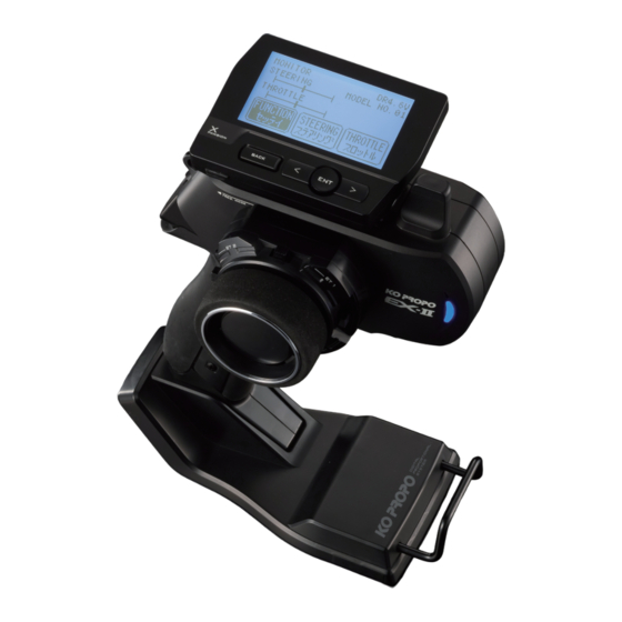
Summary of Contents for Ko Propo EX-II
- Page 1 INSTRUCTION MANUAL KONDO KAGAKU Co., Ltd. 2015 Ver.1.0...
-
Page 2: Table Of Contents
■ Table of Contents ※ Click the page number to jump to that page. Title Title Page Page ■ Table of Contents ●SYSTEM MENU ■ For Safe Operation ▶DISPLAY MENU ■ Getting Started ▶BATTERY TYPE ●Transmitter Assembly !WARNING! Warning Display ●Transmitter Dismantling ▶CALCULATOR ■... -
Page 3: For Safe Operation
Due to the nature of radio controlled models, improper handling may lead to dangerous situations. Therefore please read the following information carefully in order to ensure safe operation. Please also understand that KO Propo is not responsible for any injuries or damage which result from noncompliance of these cautions and notices. - Page 4 ※This is very dangerous and may lead to an explosion. Enforcement matters ●Use KO Propo chargers to charge the battery and use the correct current (under 1A). ※Incorrect current may lead to battery damage, overheating, or leakage. ※Other manufacturer's chargers may not have a automatic cutoff function.
-
Page 5: Getting Started
■ Getting Started [Legend] :Point :Notice ● Transmitter Assembly ● Transmitter Dismantling Insert the Grip Unit into the Master Unit, then attach Detach the Steering Unit, then detach the Master the Steering Unit. Unit. Steering Unit Remove the connector cover before use. Master Unit ③... -
Page 6: Names Of Parts
■ Names of Parts 《Side View》 《Front View》 EXP Connector Cover Antenna (P.7) (P.7) (P.7) (P.7) (P.8) (P.7) Power Switch Steering Unit Steering Unit (P.5) Release Button (P.7) (P.5) Lock Lever (P.7) Throttle Trigger Colored Grip Charger Jack (P.8) (p.7) ●... -
Page 7: Et Keys (1-5) And Bt Button
● ET Keys (1-5) and BT Button (1) ● Throttle Trigger Position Adjustment Functions may be assigned to the keys/button. The position of the throttle trigger may be adjusted to match the user's hands. The possible functions which each key/button may be [How to Adjust] assigned to are different. -
Page 8: Unit Connector
If storing the transmitter in dismantled form. After prolonged use, a black residue may build up on the connectors. Use cotton swabs dipped in cleaning alcohol to remove. KO Propo's Customer Service Department also handles transmitter maintenance. ● Power Switch This product features a safety lock. -
Page 9: Preparations
■ Preparations ● Battery Installation ● Battery Level Warning A warning will be displayed with the LED flashing and Press the tab on the bottom of the transmitter to open an alarm will sound when battery voltage is less 4v. battery box cover. -
Page 10: Initializing
● How to change the Modulation mode ● Initializing EX-2 When using the EX-2 for the first time, please carry EX-2 has two Modulation modes. out the following settings. ※ When attaching the Xpansion unit, this operation ※ EX-2 does will not work normally if the initial is the same. -
Page 11: Countermeasures Against Noise
● Countermeasures Against Noise Keep antenna cable away from all sources of noise! Noise is generated in any area where a large amount of Carbon Fiber Chassis Battery Pack electric current is flowing. Position the receiver and antenna cable as far away from the motor, battery, ESC, and their associated cables as possible. -
Page 12: Receiver Installation
This transmitter is only compatible with digital servos. Correct operation is not possible when used with analog servos. For items which are not included in this product, please refer to the KO Propo website for a list of compatible products. (http://www.kopropo.co.jp) -
Page 13: Pairing (For General Receiver)
● Pairing (For general receiver) Case without the Xpansion unit Preparing the Receiver ※ Refer to p.25 pairing Operation in the case of using ① Connect the receiver power the Xpansion unit. BATT source while pressing the setup In order for the receiver to operate, it must store the button.


Need help?
Do you have a question about the EX-II and is the answer not in the manual?
Questions and answers