Table of Contents
Advertisement
Quick Links
Advertisement
Table of Contents

Subscribe to Our Youtube Channel
Related Manuals for Icom i2730A


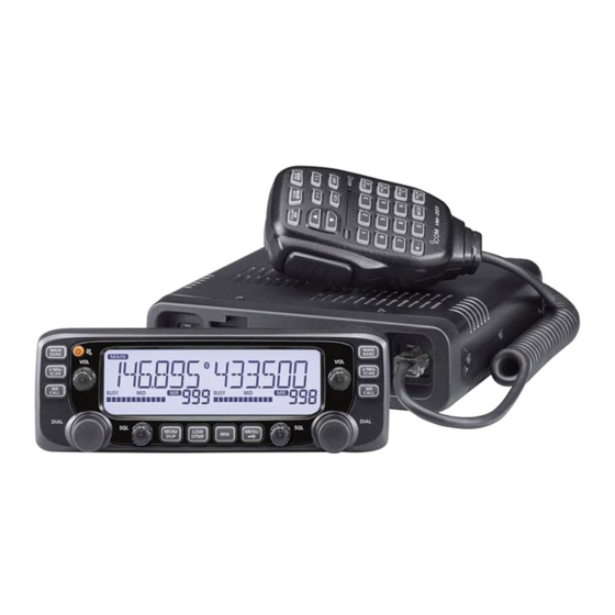
Summary of Contents for Icom i2730A
- Page 1 INSTRUCTION MANUAL DUAL BAND TRANSCEIVER i2730A i2730E...
-
Page 2: Explicit Definitions
FOREWORD IMPORTANT READ ALL INSTRUCTIONS Thank you for choosing this fine Icom product. The IC-2730A carefully and completely and IC-2730E are designed and before using the transceiver. dual band transceiver build with Icom’s superior technology and craftsmanship SAVE THIS INSTRUCTION MANUAL—... -
Page 3: Precautions
Safe driving requires your full attention—anything less and remove the power cable if it emits an abnormal odor, sound may result in an accident. or smoke. Contact your Icom dealer or distributor for advice. R WARNING! NEVER operate the transceiver with an ear-... - Page 4 The Bluetooth word mark and logos are registered trademarks is ON and your vehicle’s engine is OFF, the vehicle’s battery will owned by Bluetooth SIG, Inc. and any use of such marks by Icom soon become exhausted. inc. is under license.
-
Page 5: Table Of Contents
TABLE OF CONTENTS FOREWORD ...........i Writing into a Memory or Call channel .. 30 INSTALLATION AND CONNECTIONS . 63 ■ EXPLICIT DEFINITIONS .........i Setting a Memory bank ....32 Connecting to a DC power supply ..64 ■ ■ IMPORTANT ............i Entering a Memory or Bank name ... -
Page 6: Panel Description
PANEL DESCRIPTION ■ Controller — Front panel e VFO/MHz TUNING•SCAN KEY [V/MHz SCAN] Microphone Push to select the VFO mode. ➥ Display (p. 2) connector (pp. 5, 63) In the VFO mode, push to select 1 MHz tuning. (p. 24) ➥... -
Page 7: Controller - Display
PANEL DESCRIPTION ■ Controller — Display i MONITOR•DUPLEX KEY [DUP MONI] Push to turn the Monitor function ON and OFF. (p. 27) ➥ q w e Hold down for 1 second to display the duplex direction ➥ setting screen. (p. 50) o OUTPUT POWER•DTMF KEY [LOW DTMF] Push to select the transmit output power level. - Page 8 PANEL DESCRIPTION Controller — Display (Continued) ■ !3 VOX ICON (p. 75) Displayed when the transceiver is connected to the optional VS-3 , and the VOX function is ON. Bluetooth ® headset !4 MEMORY MODE ICON (p. 29) Displayed while in the Memory mode. !5 S/RF METER Displays the relative signal strength of the receive signal.
- Page 9 PANEL DESCRIPTION !8 ENTER KEY [ï] Push to go to the next tree level or to set the option or value in the MENU mode. (pp. 11, 30) !9 LEFT/RIGHT KEYS [Ω]/[≈] In the MENU mode (p. 11) [Ω]: Push to go back the previous tree level. [≈]: Push to go to the next tree level.
-
Page 10: Main Unit
PANEL DESCRIPTION ■ Main unit y EXTERNAL SPEAKER JACK 2 [SP2] u EXTERNAL SPEAKER JACK 1 [SP1] Front panel Rear panel Connect an 8 ohm external speaker. • See the following list for the speaker connection and audio out- put details. Ext. -
Page 11: About The Hm-207 Microphone
PANEL DESCRIPTION ■ About the HM-207 microphone With the HM-207, you can input numbers for frequency or t [HOME CALL] KEY Memory channel settings, and adjust the audio volume and Push to select the Home channel. ➥ squelch level. Hold down for 1 second to turn the Call channel mode ➥... - Page 12 PANEL DESCRIPTION Microphone (HM-207) (Continued) !6 [M .] KEY ■ Push to input a ‘.’ (decimal point) when entering a fre- ➥ quency. Push to input DTMF code ‘ M.’ ➥ • “E” stands for “M” on the display. !7 [0] to [9] KEYS Push to input a frequency, or DTMF codes ‘0’...
-
Page 13: During Rx/Standby
PANEL DESCRIPTION The following functions can be set to [F-1] and [F-2] to use during receive or in stand-by, or during transmit. (p. 14) During RX/Standby: Function Description Function Description In the VFO mode, hold down for 1 second No function to save the frequency displayed in the MAIN MONI Push to open or close the squelch. -
Page 14: Menu Mode
MENU MODE The MENU mode is used to program infrequently changed EXMENU values or function settings. MOD.TS • The MENU mode items are for the MAIN band. MODE FM/FM-N/AM/AM-N 5.0~50.0/AUTO ■ MENU mode screen DUP.T TONE OFF/TONE/TSQL /TSQL/DTCS The MENU item is displayed on the left side. DTCS/TSQL-R/DTCS-R/DTC.OFF/ The item’s option or value is displayed on the right side. - Page 15 MENU MODE EXMENU (Continued) SOUNDS FUNC BEEPLV SQLTYP OFF/S SQL/ATT KEY B OFF/ON SQL-DL SHORT/LONG HOME B OFF/ON SLOW/MID/FAST/AUTO EDGE B OFF/ON DIAL S OFF/ON STOP B OFF/ON AUTORP* OFF/ON (KOR version) SUBMUT OFF/MUTE/BEEP/MUT.BP OFF/DUP/DUP.TON (USA version) HOMECH SET.FRQ SET CH/CLEAR RMTMIC RX/TX F-1/F-2...
-
Page 16: Selecting The Menu Item
MENU MODE ■ Selecting the MENU item In addition to this page, see pages 12 through 22 for details. Rotate [DIAL] S to select the desired value. Selectable values: For your reference: 5 kHz, 6.25 kHz, 8.33 kHz*, 10 kHz, 12.5 kHz, 15 kHz, The MENU system is constructed in a tree structure. -
Page 17: Setting Items
Sets a DTCS (both encoder/decoder) code for DTCS squelch func- D EXMENU mode tion used in the FM mode. See the Icom website for details of the EXMENU mode items. DTCS polarity Sets the DTCS polarity for the DTCS squelch function. - Page 18 MENU MODE Setting items ■ Scan items EXMENU mode (Continued) Set scan options. Priority scan* DUP/TONE items Starts the Priority scan. Settings to access repeaters. Pause timer* Tone* Selects the scan pause time. When receiving signals, the scan Sets a channel tone type. pauses according to the scan pause timer.
- Page 19 MENU MODE Squelch delay Frequency high Sets the higher edge frequency for each Program scan. Set the squelch delay to prevent repeated opening and closing of the squelch when receiving the same signal. Tuning step Fan control Sets the tuning step for each Program scan. Sets the cooling fan control operation.
- Page 20 MIC gain Opening message Sets the microphone sensitivity to suit your preference. Sets whether or not to display “ICOM” and the power source volt- Auto power OFF age at power ON. Sets to automatically turn OFF the transceiver after a preset time Memory name period of inactivity.
- Page 21 MENU MODE Clear Sound items Deletes the current Home channel. Sets the Sound options. This item does not appear when no Home channel is set. Beep level Sets the beep output level. Bluetooth ® items Key-touch beep Sets the Bluetooth ®...
- Page 22 Sets the VOX Time-Out Timer to prevent an accidental prolonged Clone transmission. Sets the clone mode. Icom headset Clone mode Sets to use the optional Bluetooth ® headset (VS-3). Sets the transceiver as a sub transceiver to receive data from a Power save Master transceiver.
-
Page 23: Menu Items
MENU MODE ■ MENU items • TSQL-R: Enables the reverse tone squelch function. Tone (Default: OFF) The tone squelch does not open only when you Select a desired channel tone type. receive a signal that includes a matching tone • OFF: The function is OFF. - Page 24 MENU MODE MENU items (Continued) ■ Repeater Tone (Default: 88.5) • DTC.TSQ: When you transmit, the DTCS code is superim- posed on your normal signal. Select a CTCSS tone frequency for repeater or other tone When you receive, the tone squelch opens only squelch access.
- Page 25 MENU MODE DTCS Code (Default: 023) Tuning step (Default: 5.0) Select a DTCS (both encoder/decoder) code for the DTCS When you rotate [DIAL] in the VFO mode, the frequency squelch. changes in the selected tuning step. A total of 104 codes (023~754) are selectable. The selected tuning step is also used for a VFO mode scan.
- Page 26 MENU MODE MENU items (Continued) ■ Pause Timer (Default: 10SEC) Weather alert (Default: OFF) Select the Scan Pause time. (Appears only for the USA version transceivers.) • 2SEC to 20SEC: When a signal is received, the scan paus- Turn the Weather Alert function ON or OFF. es for 2 to 20 seconds (set in 2 second A NOAA (National Oceanographic and Atmospheric Admin- steps).
- Page 27 Push [ï]D to delete the Home channel. EXMENU mode Enters the EXMENU mode. See pages 12 to 17 for the items that you can set in the EX- MENU mode. See the Icom website for details of the EXMENU mode items.
-
Page 28: Basic Operation
BASIC OPERATION ■ Selecting the MAIN band D Call channel mode You can use the Call channel mode to operate on the Call channels. Push [MAIN BAND] S on either the left or right band to set ➥ it as the MAIN band. Hold down [MR CALL] S for 1 second. -
Page 29: Selecting The Operating Band Setting A Frequency
BASIC OPERATION ■ Selecting the operating band ■ Setting a frequency The transceiver can receive the AIR, 144 MHz or 430 MHz This section describes on the VFO mode operation. When you select other mode, push [V/MHz SCAN]S. bands. You can transmit on only the 144 MHz and 430 MHz bands. D Selecting the 1 MHz tuning •... -
Page 30: Setting Audio Volume And Squelch Level
BASIC OPERATION ■ Setting audio volume and Setting a frequency (Continued) ■ D Selecting a tuning step squelch level Rotating [DIAL]S changes the frequency in the selected tun- ing steps. • You can make the setting on either the left or right band, The VFO scan uses this step to search for a signal. -
Page 31: Transmitting
BASIC OPERATION ■ Transmitting ■ Selecting the operating mode The transceiver has a total of four operating modes, AM, AM- Before transmitting, monitor the operating frequency N, FM and FM-N. (Default: FM) to see if other stations are on the frequency. In the AIR band, the AM mode is set as a default. -
Page 32: Audio Mute Function
BASIC OPERATION ■ Audio mute function ■ Setting the microphone gain level This function temporarily mutes the audio without disturbing the volume setting. Set the microphone gain level in the MENU mode. • This function is for both the MAIN and SUB bands. Push [MENU Push [ ]( ) to mute audio signals. -
Page 33: Memory Operation
MEMORY OPERATION ■ General description D Memory channel content The transceiver has a total of 1000 Memory channels (100 channels in each of 10 memory banks, A to J) and two Call The following information can be entered into the Memory channels (C0/C1) for the 144 and 430 MHz bands. -
Page 34: Selecting A Memory Or Call Channel
MEMORY OPERATION ■ Selecting a Memory or Call channel D Selecting a Memory channel D Selecting a Call channel You can select a Memory channels by rotating [DIAL]S in the You can select the Call channels (C0/C1) by rotating [DIAL]S Memory mode. -
Page 35: Writing Into A Memory Or Call Channel
MEMORY OPERATION ■ Writing into a Memory or Call channel After setting a frequency in the VFO mode, you can write it • You can also select Call channels. • To select Bank channel, hold down [MAIN BAND]S for 1 second. into your desired channel or an automatically selected blank channel. -
Page 36: Memory Channel
MEMORY OPERATION Writing into a Memory or Call channel (Continued) ■ D Copying Memory content to the VFO D Copying Memory content to another Memory channel This is convenient when you want to change the frequency beginning near the Memory or Call channel frequency. You can copy the memory content to another Memory chan- nel. -
Page 37: Setting A Memory Bank
MEMORY OPERATION ■ Setting a Memory bank D Assigning a Memory channel to a Memory bank The transceiver has a total of 10 banks (A to J). You can assign regular Memory channels 0 to 999 to any Select the Memory channel to be assigned to a bank. desired bank for easy memory management. -
Page 38: Directly Entering Into A Memory Bank
MEMORY OPERATION Setting a Memory bank (Continued) ■ D Directly entering into a Memory bank D Selecting the Memory bank mode You can also enter the memory content directly into a memo- When you select the Memory bank mode, rotating [DIAL] ry bank channel. -
Page 39: Entering A Memory Or Bank Name
MEMORY OPERATION ■ Entering a Memory or Bank name • Selectable characters and symbols: [ I ] You can enter an alphanumeric name for each Memory chan- nel, Call channel, and Bank. Names can up to 6 characters. • The operations are for the MAIN band. ”... -
Page 40: Clearing A Memory Channel
MEMORY OPERATION ■ Clearing a Memory channel Entered memory content can be cleared (erased), if desired. NOTE: Once you clear a memory content, it cannot be re- covered. • The operations are for the MAIN band. Push [MR CALL] • Selects the Memory mode. •... -
Page 41: Scan Operation
SCAN OPERATION ■ About the scan function For your reference: The frequencies that are set as “PSKIP” are not scanned. (p. 13) D VFO scan (p. 41) NOTE: At least one program scan edge range must be • ALL (Full scan) programmed to start a program scan. -
Page 42: Tuning Step For A Vfo Scan
SCAN OPERATION About the scan function (Continued) ■ D [DIAL] operation during a scan [Duplex (DUP) scan] • If desired, rotate [DIAL]S to change the scanning direction The Duplex scan searches for both TX and RX frequencies during a scan. that are used in duplex operation. -
Page 43: Entering Scan Edges
SCAN OPERATION ■ Entering scan edges D Receive mode during a scan • The selected mode is used by the scan. • During a memory or bank scan, the channel’s mode is used Enter the higher and lower frequency edges as the scan edge by the scan. - Page 44 SCAN OPERATION Entering scan edges (Continued) • Selectable characters and symbols: ■ Entering a scan name [ I ] Push [MENU • Enters the MENU mode. w Rotate [DIAL]S to select “P-EDGE” ( Program Scan Edge (MENU-EXMENU > EXMEN-SCAN > SCAN-P-EDGE) ”...
- Page 45 SCAN OPERATION Setting a operating mode !4 Rotate [DIAL] to select a desired number. !5 Push [Ω] to move the cursor backwards, or push [≈] to move the cursor forwards. NOTE: !6 Repeat steps !4 and !5 to enter a lower edge frequency. •...
-
Page 46: Vfo Mode Scan
When a program link name is assigned, it is displayed on the Push [V/MHz SCAN] S to start the scan. scan type setting screen. (Step e on this page) To cancel the scan, push [V/MHz SCAN] See the Icom website to enter a program link name. -
Page 47: Setting And Clearing The Skip Frequencies
SCAN OPERATION ■ Setting and clearing the skip frequencies D Setting the skip frequencies D Clearing the skip frequencies The frequencies set as “PSKIP” channels are not scanned. Push [MR CALL] • Selects the Memory mode. Rotate [DIAL] to select the memory channel you want to Start the VFO scan. -
Page 48: Memory Scan
SCAN OPERATION ■ Memory scan D Memory bank scan A memory bank scan searches through the memory chan- nels in the selected bank. There two types of scans in the memory mode; Memory scan • Two or more memory channels, that are not set as skip channels, and Memory bank scan. -
Page 49: Setting And Clearing Skip Channels
SCAN OPERATION ■ Setting and clearing skip ■ Setting the temporary skip channels function The channels that are set as “SKIP” or “PSKIP” channels are This function temporarily skips up to five unwanted frequen- skipped (not scanned). cies during a scan, for the set time period, without setting the skip frequency. -
Page 50: Priority Watch
PRIORITY WATCH ■ Priority watch D VFO and a Memory/Bank scan While operating on a VFO frequency or while scanning, Pri- (p. 47) ority watch checks for signals on a selected frequency every Sequentially checks the Memory or Bank channels every 5 sec- 5 seconds. -
Page 51: Vfo And A Priority Channel
PRIORITY WATCH ■ VFO and a Priority channel D VFO frequency and a Priority channel Checks the selected Priority channel every 5 seconds, while Example: Checks Memory channel “11” while receiving on receiving on a VFO frequency. 433.920 MHz. Set the VFO frequency. (p. 24) Set the Priority channel. -
Page 52: Vfo And A Memory/Bank Scan
PRIORITY WATCH ■ VFO and a Memory/Bank scan Example: Sequentially checks the Memory channels while re- ceiving on 433.920 MHz. D VFO frequency and a Memory/Bank scan Sequentially checks the Memory or Bank channels every 5 seconds, while receiving on a VFO frequency. Appears Set the VFO frequency. -
Page 53: Repeater And Duplex Operations . 48
REPEATER AND DUPLEX OPERATIONS ■ Repeater operation A repeater receives signals on one frequency, and then re- Hold down [MONI DUP] transmits them on a different frequency. When using a re- • Displays the duplex direction setting screen. (p. 50) peater, the transmit frequency is shifted from the receive fre- Rotate [DIAL] to select a desired offset direction. -
Page 54: D 1750 Hz Tone Burst
REPEATER AND DUPLEX OPERATIONS Repeater operation (Continued) ■ D 1750 Hz tone burst For your reference: A 1750 Hz tone is required to access many European repeat- • If the Repeater tone frequency or the frequency offset is ers. changed, the tone or offset for the Auto Repeater function This function can be used only when the supplied HM-207 or is also changed. -
Page 55: Duplex Operation
REPEATER AND DUPLEX OPERATIONS ■ Duplex operation D Setting the duplex direction The Duplex operation shifts the transmit frequency up or down from the receive frequency by an offset amount. Hold down [MONI DUP] • This section describes the MAIN band operation. •... -
Page 56: Off Band Indication
REPEATER AND DUPLEX OPERATIONS ■ Off band indication Duplex operation (Continued) ■ D Duplex operation If the transmit frequency is out of the amateur band, the off Push [MONI DUP] to listen to the transmit frequency to band indication, “OFF,” appears on the display when [PTT] is check whether another station is transmitting on it, or not. -
Page 57: Auto Repeater Function
REPEATER AND DUPLEX OPERATIONS ■ Auto repeater function When the operating frequency falls within the repeater output For the U.S.A. and Korean versions: frequency range, the Auto Repeater function automatically When turned ON, the Auto repeater function has priority sets the repeater settings (duplex ON/OFF, duplex direction, over the manual duplex setting. -
Page 58: Other Functions
OTHER FUNCTIONS ■ Home Channel Beep function When you select a Home channel by rotating [DIAL]S, a Push [ ï]D. beep sounds. You will know the Home channel is selected • Beeps sound • Sets the Home channel, and exits the MENU mode. without looking at the display. -
Page 59: Using The Dtmf Memory
OTHER FUNCTIONS ■ Using the DTMF Memory The transceiver can store up to 16 Memory channels of Rotate [DIAL] to select a desired number to enter a 24-digit DTMF codes. code. • “E” stands for “M” and “F” stands for “#” on the display. D Entering a DTMF code Hold down [LOW DTMF] C for 1 second. -
Page 60: Transmitting Dtmf Code
OTHER FUNCTIONS ■ Transmitting DTMF code D Transmitting DTMF code (DTMF Memory) D Transmitting DTMF code (Direct Input) Hold down [LOW DTMF] C for 1 second. Hold down [LOW DTMF] C for 1 second. • Enters the DTMF Menu mode. •... -
Page 61: Tone Squelch Function
OTHER FUNCTIONS ■ Tone Squelch function D Selecting the DTMF transmit speed The squelch opens only when you receive a signal containing a matching subaudible tone in the FM or FM narrow mode. You can select the DTMF transmit speed. You can silently wait for calls from others using the same tone. - Page 62 OTHER FUNCTIONS Tone Squelch function (Continued) ■ • OFF: The Tone Squelch function is OFF. Push [ ï]D. • TONE: Enables the subaudible tone encoder. • Sets the selected option, and goes back to the previous tree level. Push [MAIN BAND] •...
-
Page 63: Setting The Tone Frequency
OTHER FUNCTIONS D Setting the Tone frequency D Setting the Repeater Tone frequency Push [MENU Push [MENU • Enters the MENU mode. • Enters the MENU mode. w Rotate [DIAL]S to select “C TONE” (TSQL Freq). w Rotate [DIAL]S to select “R TONE” (Repeater Tone). Push [ ï]D. -
Page 64: Setting The Dtcs Code
OTHER FUNCTIONS Tone Squelch function (Continued) ■ D Setting the DTCS code D Setting the DTCS polarity Push [MENU Push [MENU • Enters the MENU mode. • Enters the MENU mode. w Rotate [DIAL]S to select “CODE” (DTCS Code). w Rotate [DIAL]S to select “DTCS-P” (DTCS Polarity). Push [ ï]D. -
Page 65: Weather Channel Operation
OTHER FUNCTIONS ■ Weather channel operation The previously selected (used) weather channel is checked periodically during standby, or while scanning. (USA version only) Push [MENU There are 10 weather channels to listen to the NOAA (Nation- • Enters the MENU mode. al Oceanographic and Atmospheric Administration) weather w Rotate [DIAL]S to select “WX-ALT”... -
Page 66: Cloning Function
S to select “CLONE” (Clone Mode). See the CS-2730 instruction manual for details. (downloaded ï]D. Push [ from the Icom WEB site; http://www.icom.co.jp/world/) • Displays “CLONE?.” o Rotate [DIAL]S to select “YES.” D Cloning between transceivers Connecting the master and sub transceivers Select a master transceiver to send data to a sub transceiver. - Page 67 OTHER FUNCTIONS Setting the master transceiver !8 Push [ï]D. • Displays “CLONE OUT” on the master transceiver’s display. !1 Push [MENU ]C of the master transceiver. • Enters the MENU mode. !2 Rotate [DIAL]S to select “CLONE” (Clone). (MENU-EXMENU > EXMEN-OTHERS > OTHER-CLONE) !3 Push [ï]D.
-
Page 68: Connecting The Controller To The Main Unit
INSTALLATION AND CONNECTIONS ■ Connecting the controller to MBA-4 Controller (Rear) Screw* the main unit Projection tab Connect the controller to the main unit with the supplied con- Cable* trol cable. *Supplied with the MBA-4 • The following longer cables may be required, depending on the installation location. -
Page 69: Connecting To A Dc Power Supply
INSTALLATION AND CONNECTIONS ■ Connecting to a DC power ■ Installing the controller supply D When installing into your vehicle You can install the controller on the dashboard or the console Connect to a 13.8 V DC power source with at least 15 A ca- of your vehicle with the optional MBA-5 controller bracket pacity. - Page 70 INSTALLATION AND CONNECTIONS Installing the controller (Continued) ■ D Attaching to a flat surface Slide the MBA-5 ’s guide down over the MBF-1’s locking head, as shown below. You can install the controller on a flat surface with the optional •...
-
Page 71: Installing In A Vehicle
INSTALLATION AND CONNECTIONS ■ Installing in a vehicle (Except for the EU countries’ transceiver) D Using the mounting bracket You can install the main unit on the dashboard or the console CAUTION: NEVER place the main unit or remote controller of your vehicle with the optional MBF-4 mobile bracket where normal operation of the vehicle may be hindered or... -
Page 72: Installing An Antenna
INSTALLATION AND CONNECTIONS ■ Installing an antenna D About Coaxial cable • Antenna location For radio communications, the antenna is of critically impor- tance, along with output power and receiver sensitivity. Select a well-matched 50 ˘ antenna and coaxial cable feed- line. -
Page 73: Connecting To A Battery
INSTALLATION AND CONNECTIONS ■ Connecting to a battery RWARNING! RWARNING! • NEVER remove the fuses from the cable connecting the • Make sure DC power cable polarity is correct. transceiver to a power source, especially a car battery. Red: Positive + terminal •... - Page 74 INSTALLATION AND CONNECTIONS Connecting to a battery (Continued) ■ CONNECTING TO A VEHICLE BATTERY Grommet NOTE: Use terminals for the cable connections. black Crimp Solder 12 V battery Supplied DC power cable...
-
Page 75: Options
Approved Icom optional equipment is designed for optimal performance when used with an Icom transceiver. Icom is not responsible for the destruction or damage to an Icom transceiver in the event the Icom transceiver is used with equipment that is not manufactured or approved by... -
Page 76: Operation
® Bluetooth OPERATION ■ Operating Bluetooth ® When you install the optional UT-133 Bluetooth ® in the unit ® transceiver, you can connect to other Bluetooth devices. UT-133 In this section, the IC-2730A/E with the UT-133 is described as simply “transceiver.” Optional VS-3 Bluetooth ®... -
Page 77: Installing The
Bluetooth ® OPERATION ■ Installing the UT-133 Place one end the UT-133 under the edge of the front pan- el, with the connector facing down. When you install the optional UT-133 Bluetooth ® in the unit Front panel ® transceiver, you can communicate with other Bluetooth UT-133 headset. -
Page 78: Pairing With A Headset
® Bluetooth OPERATION ■ Pairing with a headset Appears This section describes how to pair with a Bluetooth ® headset. Turning ON Bluetooth ® of the transceiver Push [MENU • Enters the MENU mode. w Rotate [DIAL]S to select “BT” (Bluetooth ®... -
Page 79: Vox Function
Bluetooth ® OPERATION ■ VOX function The VOX (Voice-Operated Transmission) function toggles the D Setting the VOX level transceiver between transmit and receive by your voice. This NOTE: We recommend you set the “MIC G” (MIC gain) item function provides hands-free operation. in EXMENU or the headset’s microphone gain level, before setting the “VOX LV”... -
Page 80: Other Headset Settings
® Bluetooth OPERATION ■ Other headset settings VOX function (Continued) ■ D VOX-related settings D AF Output You can set the “VOX.DLY” (VOX delay) and “VOX.TOT” (VOX If the “AF OUT” (AF output) item is set to “HS+SP” (Headset Time-out timer) items in EXMENU. (p. 17) &... - Page 81 Bluetooth ® OPERATION D About the VS-3 headset • Custom Key Beep “CUST B” (p. 17) You can set the detailed settings of the optional VS-3 Blue- . Also, you can assign a desired key function to Set a beep to sound when you push [PLAY], [FWD] or [RWD] ®...
-
Page 82: The Maximum Number Of Paired Devices
® Bluetooth OPERATION ■ The maximum number of ■ Deleting a Bluetooth ® device from the pairing list paired devices You can delete a Bluetooth ® device from the pairing list. ® Up to seven Bluetooth devices can be paired with the UT- ®... -
Page 83: Resetting The Installed Bluetooth ® Unit
Bluetooth ® OPERATION ■ Resetting the installed Bluetooth ® unit You can reset the installed UT-133 Bluetooth ® unit ® You should reset the unit if you have trouble during Bluetooth operation. When you do a Partial reset or All reset, the Bluetooth ®... -
Page 84: Specifications
SPECIFICATIONS D General • Frequency coverage: • Frequency stability: ±2.5 ppm 118–174 MHz* , 375–550 MHz* (−10˚C to +60˚C; +14˚F to +140˚F) 144–146 MHz, 430–440 MHz • Frequency resolution: 5 kHz, 6.25 kHz, 8.33 kHz, 10 kHz, 118–136.99166 MHz* , 144–146 MHz, 12.5 kHz, 15 kHz, 20 kHz, 25 kHz, 430–434 MHz, 435–438 MHz 30 kHz, 50 kHz... - Page 85 SPECIFICATIONS Transmitter Receiver • Modulation system: • Receive system: Double superheterodyne system FM/FM-N: Variable reactance frequency • IF frequencies: modulation A band 1st IF 38.85 MHz • Max Deviation: 2nd IF 450 kHz ≤ ±5.0 kHz B band 1st IF 46.35 MHz ≤...
-
Page 86: Resetting
MAINTENANCE ■ Resetting D All Reset Occasionally, erroneous information will be displayed when, for example, first applying power. This may be caused exter- BE CAREFUL! An All reset clears all programming and nally by static electricity or by other factors. returns all settings to their factory defaults. -
Page 87: Power Protect Function
NOTE: When the power supply voltage is over 17.0 V, the transceiver automatically displays “OVER V,” and then sounds a warning beep. In this case, the transceiver may be damaged. If damage occurs, contact your nearest Icom R WARNING! NEVER remove the fuse holders from the Dealer or Service Center. -
Page 88: Troubleshooting
The following chart is designed to help you correct problems If you are unable to locate the cause of a problem, or solve which are not equipment malfunctions. it through the use of this chart, contact your nearest Icom Dealer or Service Center. PROBLEM... - Page 89 MAINTENANCE PROBLEM POSSIBLE CAUSE SOLUTION REF. Transmitting is impossible. • The PTT Lock function is activated. • Set the PTT Lock function to OFF in EXMENU. p. 15 • The Busy Lockout function is activated. • Set the Busy Lockout function to OFF in EX- p.
-
Page 90: Information
Latvia • Consult the dealer or an experienced radio/TV technician for help. CAUTION: Changes or modifications to this device, not ex- pressly approved by Icom Inc., could void your authority to operate this device under FCC regulations. -
Page 91: Index
INDEX [DIAL] operation during a scan ...........37 Headset settings 1750 Hz tone burst .............49 AF Output..............75 VS-3 headset ............76 VOX function .............74 AF Output ................75 Pairing with a headset ............73 All Reset ................81 Resetting the installed Bluetooth ® unit .......78 Antenna The maximum number of paired devices ......77 Coaxial cable ..............67... - Page 92 INDEX Other items ..............17 C (Continued) Copy Scan items ..............13 Copying Memory content to another Memory channel ..31 Sound items ..............16 Copying Memory content to the VFO ......31 Explicit definitions ..............i Country code list ..............85 FCC information ..............85 Duplex operation ............50, 51 Foreword ................
- Page 93 INDEX Selecting the MENU item ..........11 Setting items ..............12 Lock function ..............25 Microphone Connecting a microphone ..........63 Maintenance ...............81 HM-207 microphone ............6 MAIN band selection ............23 Key functions for [F-1] or [F-2] Main unit ................5 During RX/Standby ..........8 Main unit installation ............66 During TX ..............8 Memory operation ..............28 Microphone connector information ........5...
- Page 94 INDEX Panel description ..............1 Scan function ..............36 Partial Reset ...............81 Bank link scan ..............36 Power protect function ............82 Bank scan ..............36 Power Save .................76 Entering scan edges ............38 Precautions ................ii VFO scan ...............36 Priority watch ..............45 Full bank scan ............36 VFO and a Memory/Bank scan ........45, 47 Full scan..............36 VFO and a Priority channel ........45, 46...
- Page 95 INDEX Specifications ..............79 General ................79 VFO mode ................23 Receiver .................80 VFO mode scan ..............41 Transmitter ..............80 VFO scan ................36 Spurious signals ..............82 VFO scan and a Memory/Bank scan ........47 Squelch level setting ............25 VFO scan and a Priority channel ........46 Supplied accessories.............
- Page 96 ■ ■ ■ ■ ■ ■ ■ ■ ■ ■ ■ ■ ■ ■ ■ ■ ■ ■ ■ A-7194H-1EX Printed in Japan 2014 Icom Inc. © 1-1-32 Kamiminami, Hirano-ku, Osaka 547-0003, Japan Printed on recycled paper with soy ink.
Need help?
Do you have a question about the i2730A and is the answer not in the manual?
Questions and answers