
Related Manuals for Ametek CSW5550


Summary of Contents for Ametek CSW5550
- Page 1 Revision F January 2014 Copyright 2011 by AMETEK Programmable Power. All rights reserved. P/N M162084 CSW Series AC Power Source User Manual...
- Page 2 CSW11100-400 CSW16650 CSW16650-400 CSW22200 CSW22200-400 CSW27750 CSW27750-400 CSW33300 CSW33300-400 CSW38850 CSW38850-400 CSW44400 CSW44400-400 Copyright 2011 AMETEK Programmable Power. Rev C, January 2012. CSW Series...
- Page 3 California Instruments About AMETEK AMETEK Programmable Power, Inc., a Division of AMETEK, Inc., is a global leader in the design and manufacture of precision, programmable power supplies for R&D, test and measurement, process control, power bus simulation and power conditioning applications across diverse industrial segments.
-
Page 4: Important Safety Instructions
Neither AMETEK Programmable Power Inc., San Diego, California, USA, nor any of the subsidiary sales organizations can accept any responsibility for personnel, material or inconsequential injury, loss or damage that results from improper use of the equipment and accessories. - Page 5 User Manual California Instruments CSW Series...
- Page 6 AMETEK will, at its expense, deliver the repaired or replaced Product or parts to the Buyer. Any warranty of AMETEK will not apply if the Buyer is in default under the Purchase Order Agreement or where the Product or any part thereof: is damaged by misuse, accident, negligence or failure to maintain the same as ...
-
Page 7: Table Of Contents
User Manual California Instruments Table of Contents Introduction ..........................12 General Description ..........................12 CSW Models ............................13 Specifications ..........................14 Electrical .............................. 14 Mechanical ............................24 Environmental ............................ - Page 8 User Manual California Instruments Sub assemblies ..........................121 Options ............................. 122 RTCA/DO-160 Option ........................122 IEC 61000-4-11 Option ........................139 IEC 61000-4-13 Option ........................147 Option –704: MilStd704 Tests ......................159 ...
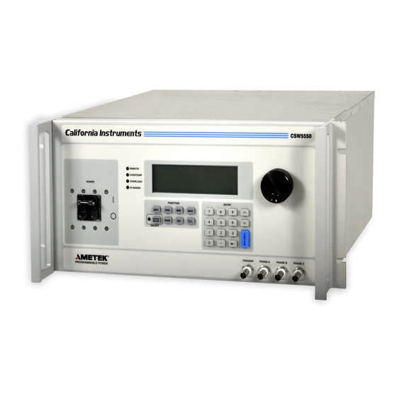
- Page 9 Figure 1-1 California Instruments CSW5550 (With Rack Mount Ears) ..............12 Figure 2-1: CSW5550 – Typical Current De-Rating Chart for 156v AC Range ........... 17 Figure 2-2: CSW5550 – Typical Current De-Rating Chart for 312v AC Range ........... 18 ...
- Page 10 User Manual California Instruments Figure 8-6: Power Interrupt ..........................129 Figure 8-7: Power Interrupt for Group 2 and 3 ....................130 Figure 8-8: Emergency Screen ......................... 131 Figure 8-9: Abnormal Screen ..........................133 Figure 8-10: DO-160 DC Main Menu ........................ 135 ...
- Page 11 User Manual California Instruments List of Tables Table 3-1: Wire Sizes ............................31 Table 3-2: System Interface Connector (J32) ..................... 32 Table 3-3: RS232 Connector pin out ........................34 Table 3-4: USB Connector pin out........................34 ...
-
Page 12: Introduction
115/230V to full-scale voltage using a constant power mode of operation. Two to eight CSW5550 units can be connected in parallel as a single-phase or 3-phase power system for an output of up to 44.4 KVA. They can be operated with AC or DC output. -
Page 13: Csw Models
User Manual California Instruments 1.2 CSW Models CSW5 C 0 C X 0 0 0 0 Model CSW5550= CSW5 CSW11100 = CSW11 CSW16650 = CSW16 CSW22200 = CSW22 CSW27750 = CSW27 CSW33300 = CSW33 CSW38850 = CSW38 CSW44400 = CSW44... -
Page 14: Specifications
User Manual California Instruments 2. Specifications All specifications are for a single CSW5550 unit and 25 5C sine wave output with a resistive load unless noted otherwise. 2.1 Electrical 2.1.1 Input Function Specification Input Power Standard: 208 to 240V ±10%, 3, 3 wire or... - Page 15 User Manual California Instruments 2.1.2 Output (ALL SPECIFICATIONS ARE FOR AC AND DC UNLESS NOTED OTHERWISE) Function Specification 1 year Calibration Interval Power Factor of Load 0 lagging to 0 leading AC or DC Output 0 to 156 VRMS L-N range ; 0 to 312 VRMS L-N range Voltage Output Current Per 16A to 115V in 156V range;...
- Page 16 40K for each of the three inputs. XLOAD The CSW5550 is guaranteed to be stable for power factors from 0 leading to 0 lagging. The most difficult load for most amplifiers is driving large capacitive loads (10-10,000F).Though stable with its normal loop compensation, the CSW can provide additional phase/gain margin with these unusual loads by selecting XLOAD On.
-
Page 17: Figure 2-1: Csw5550 - Typical Current De-Rating Chart For 156V Ac Range
User Manual California Instruments OUTPUT CURRENT DE‐RATING FROM 45Hz TO 5kHz Current (RMS) <400Hz 1KHz 2KHz 3KHz 4KHz 5KHz Voltage (RMS) Figure 2-1: CSW5550 – Typical Current De-Rating Chart for 156v AC Range per Phase CSW Series... -
Page 18: Figure 2-2: Csw5550 - Typical Current De-Rating Chart For 312V Ac Range
User Manual California Instruments OUTPUT CURRENT DE‐RATING FROM 45Hz TO 5kHz Current (RMS) <400Hz 1Khz 2Khz 3KHz 4KHz 5KHz Voltage (RMS) Figure 2-2: CSW5550 – Typical Current De-Rating Chart for 312v AC Range per Phase CSW Series... - Page 19 User Manual California Instruments Output Parameter CSW5550 (multiply current and power by the number of power sources in multi-source power systems) Current Limit Range Programmable 0 to 100% of range for all ranges Resolution 0.01 Arms Accuracy ± 1% of Range. Add ±1.5%/kHz above 500 Hz Frequency Range: 16.00 - 81.91 Hz (0.01 Hz resolution)
- Page 20 User Manual California Instruments 2.1.3 Measurements (All specifications are at 25˚C unless noted otherwise) Parameter Resolution Accuracy () Frequency 2 counts 0.01: 16 to 81.91 Hz ˚C 0.1: 82.0 to 819.0 Hz 0 to 45 1: 820 to 5000 Hz RMS Voltage ±0.1% of range from 5 to 156 or 10 0.01 Volt...
- Page 21 User Manual California Instruments 2.1.4 Harmonic Measurements (CSW series) Accuracy ( ) Parameter Range Resolution Frequency fundamental 16.00 - 1000 Hz 2 counts 0.01 Hz to 1 Hz Frequency harmonics 32.00 Hz - 16 kHz 2 typ. 0.5 Voltage Fundamental 0.25V 0.01V...
- Page 22 User Manual California Instruments 2.1.5 System Specification Parameter Specification NV memory storage: 16 complete instrument setups and transient lists, 100 events per list. Waveforms Sine, square, clipped, user defined Transients Voltage: drop, step, sag, surge, sweep Frequency: step, sag, surge, sweep Voltage and Frequency: step, sweep IEEE-488 Interface: SH1, AH1, T6, L3, SR1, RL2, DC1, DT1...
- Page 23 User Manual California Instruments System Specification (continued) Parameter Specification Front Panel Trigger, Output available at the front panel BNC connector that provides a BNC connector negative going pulse for any programmed voltage or frequency change. The trigger can be reassigned as an output when running list transients.
-
Page 24: Mechanical
User Manual California Instruments 2.2 Mechanical Parameter Specification Dimensions: 19” (483 mm) wide x 8.75” (222 mm) high x 23.5” (597 mm) deep chassis size which is available in a rack mount or stand-alone configuration. Unit Weight: 126.5 lb. (57.2 kg) Material: Steel chassis and front panel, Aluminum top cover and rear panel. -
Page 25: Regulatory
User Manual California Instruments 2.4 Regulatory Electromagnetic Designed to meet EN50081-2 and EN50082-2 European Emissions and Immunity: Emissions and Immunity standards as required for the “CE” mark. Acoustic Noise: 65 dBA maximum at 0% to 50% load, 75 dBA maximum greater than 50% load to 100% load. -
Page 26: Special Features, Options And Accessories
User Manual California Instruments 2.6 Special Features, Options and Accessories Option Description - 704 Mil Std 704D & E test firmware. Mil Std 704A, B, C, & F test software (refer to Avionics Software Manual P/N 4994-971 for details). Note: Requires use of CSWGui Windows application software provided on CD ROM CIC496. -
Page 27: Supplemental Specifications
User Manual California Instruments 2.7 Supplemental Specifications Supplemental specifications are not warranted and generally reflect typical performance characteristics. These characteristics have been checked on a type test basis only and are not verified on each unit shipped. They are provided for reference only. 2.7.1 Output Output Parameter Voltage:... -
Page 28: Unpacking And Installation
WARNING: This power source weighs 126.5 lb (57.2kg). Obtain adequate help when moving or mounting the unit. 3.2 Power Requirements The CSW5550 Power Source has been designed to operate from a 3-phase, 3-wire, 187 to 264 , AC line or a 3-phase, 4-wire, 342 to 457 V ,AC line (option -400). -
Page 29: Mechanical Installation
User Manual California Instruments 3.3 Mechanical Installation The CSW series power sources are completely self-contained power sources. They may be used free standing on a bench top or rack mounted using the rack mount/handle kit. The units are fan cooled, drawing air in from the sides and exhausting at the rear. The sides of each unit must be kept clear of obstruction and a 6”... -
Page 30: Output Power Connections - Tb2
User Manual California Instruments 3.4.3 Single-Phase Input Connections The CSW system is designed for three-phase input power operation, either 3-wire (USA) or 4-wire (EUR) plus a chassis safety ground. However, if only single-phase input power is available, the configurations listed in paragraph 2.1.1 are possible. 3.5 Output Power Connections –... -
Page 31: Table 3-1: Wire Sizes
User Manual California Instruments OLUMN OLUMN OLUMN OLUMN SIZE AMPERES OHMS/100 FEET IR DROP/100 FEET (AWG) (MAXIMUM) (ONE WAY) (COL. 2 X COL. 3) 0.257 3.85 0.162 3.24 0.102 3.06 0.064 2.56 0.043 2.36 0.025 1.75 0.015 1.42 0.010 1.25 0.006 1.04 Recommended Wire Gauge Selection Guide... -
Page 32: Connectors - Rear Panel
User Manual California Instruments 3.6 Connectors - Rear Panel A number of connectors are located on the rear panel of the power source. The connectors are identified by J numbers. The terminal strips are identified by TB numbers. 3.6.1 System Interface, Clock and Lock Connectors, J33 and J34 J33 and J34 are the Clock and Lock connectors. - Page 33 NOTE: Do not reverse or swap sense connection phasing or damage to the unit may result. For systems consisting of multiple CSW5550 chassis, the end user has to connect the external sense inputs of the Master power source for the correct External sense function. The Auxiliary power sources will have no control of the output voltage.
-
Page 34: Figure 3-2:Usb Connector Pin Orientation
User Manual California Instruments 3.6.3 RS232C Serial Interface Connector Name Direction Output Input Common Common Input Output Table 3-3: RS232 Connector pin out The CSW series power sources use a regular straight-through DB9 male to DB9 female serial cable for the RS232 interface. 3.6.4 USB Interface A standard USB Series B device connector is located on the rear panel for remote control. -
Page 35: Table 3-5: Rj45 Lan Connector Pin Out
User Manual California Instruments 3.6.5 LAN Interface – RJ45 An optional RJ45 Ethernet 10BaseT connector is located on the rear panel for remote control. A standard RJ45 UTP patch cord between the AC Source and a network Hub may be used to connect the AC source to a LAN. -
Page 36: Single-Phase And Three Phase Multiple Box System Configurations
User Manual California Instruments Figure 3-3: Rear Panel View for the CSW5550) 3.7 Single-Phase and Three Phase Multiple Box System Configurations Three Phase System: Refer to Figure 3-4 for the output power connections for a 3-phase power system. For connections to a single power source disregard the connections to the Auxiliary power sources shown in Figure 3-4. -
Page 37: Output Voltage Ranges
User Manual California Instruments See Table 3-1 for cable sizing. NOTE After the power source system has been configured for the 1-phase mode of operation the Phase B and C outputs must be reconfigured as shown in Figure 3-7 for the 3-phase mode. When the multi-source system is powered up the order of powering the Auxiliary power sources and the Master power source is not important. - Page 38 9. Repeat steps 4 through 8 for each of the three phases. In the unlikely event the power source does not pass the functional test, refer to the calibration procedure in Section 6 or call the Ametek customer service department for further assistance. CSW Series...
-
Page 39: Figure 3-4: Output Power Connections For 1 Source And Multi-Source Systems
User Manual California Instruments Figure 3-4: Output Power Connections for 1 Source and Multi-source Systems NOTE: Connect all source Output Neutral terminals CSW Series... -
Page 40: Figure 3-5: Functional Test Setup
User Manual California Instruments Figure 3-5: Functional Test Setup CSW Series... -
Page 41: Figure 3-6: Three Csw Sources, 9-Phases With Clock/Lock
User Manual California Instruments Figure 3-6: Three CSW Sources, 9-phases with Clock/Lock CSW Series... - Page 42 User Manual California Instruments Figure 3-7a: Parallel (single phase) Connections Figure 3-7b: Sense Lead Connection for 3-phase Output CSW Series...
-
Page 43: Tour Of The Front Panel
User Manual California Instruments Front Panel Operation 3.10 Tour of the Front Panel Before operating the AC source using the front panel, it helps to understand the operation of the front panel controls. Specifically, the operation of the knob, keyboard and the menu layout are covered in the next few paragraphs. -
Page 44: Figure 3-7: Shuttle Knob
User Manual California Instruments 3.10.4 The Shuttle Knob Counter Clock Clock wise wise DECR INCR Figure 3-7: Shuttle Knob The shuttle knob is located to the right of the LCD screen and is used to change setup parameters. Note that it cannot be used to move the cursor position between menu fields. Use the UP and DOWN arrow keys in the FUNCTION keypad for this. -
Page 45: Figure 3-8: Function Keypad
User Manual California Instruments 3.10.5 FUNCTION Keypad The function keypad provides access to all menus and measurement screens. The following keys are located in the FUNCTION keypad: FUNCTION MENU PROG WAVE MEAS OUTPUT PHASE ON/OFF Figure 3-8: FUNCTION keypad DESCRIPTION MENU The top level menu is accessed by pressing the MENU key. -
Page 46: Figure 3-9: Entering Value From Decimal Keypad
User Manual California Instruments OUTPUT ON/OFF The OUTPUT ON/OFF key toggles the output relay on or off. The state of the output relay is reflected by the green LED located directly to the left of the OUTPUT ON/OFF key. If the green LED is lit, the output relay is enabled (closed) and the programmed output voltage is present at the output terminals. -
Page 47: Figure 3-10: Cursor Up Key Movement
User Manual California Instruments CURSOR UP The UP key moves the cursor position upwards one position to the previous available cursor position. If the present cursor position is at the top of the right hand column, the cursor is moved to the bottom position of the left hand column. If the present cursor is at the top of the left hand column, the cursor is moved to the bottom of the right hand column. -
Page 48: Figure 3-12: Main Menu 1 Screen
User Manual California Instruments 3.10.7 LCD Display The LCD display of the CSW Series power source provides information on instrument settings and also guides the user through the various menus. To ease reading of the displayed information, most screens are widely spaced. A sample of the main menu 1 screen that appears when the source is powered up is shown in Figure 3-12. -
Page 49: Menu Structure
User Manual California Instruments 3.11 Menu Structure The next few pages show a map of the available menus in the i/CSW Series. There are three main level (level 1) menus from which all other menus can be reached. Frequently used (level 2) menus have a short cut key that provides direct access. - Page 50 User Manual California Instruments The following top-level menu choices can be accessed from the MENU key: Entry Description MENU 1 PROGRAM The PROGRAM menu allows output parameters the be changed. MEASUREMENTS The MEASUREMENTS screens are not menus in that no user entries are required.
- Page 51 User Manual California Instruments 3.11.2 Overview of Menu 1 level 2 level 3 level 1 MENU 1 PROGRAM PROGRAM1 VOLTAGE FREQ VOLT RANGE CURR LIMIT MORE PROGRAM2 PHASE CLOCK MODE VOLT MODE DC OFFSET START ø MEASUREMENTS MEASUREMENTS1 VOLTAGE CURRENT FREQ POWER MORE...
- Page 52 User Manual California Instruments 3.11.3 Overview of Menu 2 and 3 level 2 level 3 level 1 MENU 2 ADVANCE HARMONICS/TRACE MEAS. ANALYSIS FUNCTION VIEW DATA MODE SCALE TRIG MODE TRIG SOURCE TRIG PHASE TRIG DELAY START PREVIOUS SCREEN APPLICATIONS SETUP 1 STEADY STATE APPLICATIONS MIL-STD 704...
-
Page 53: Figure 3-14: Program Menu
User Manual California Instruments 3.11.4 PROGRAM Menu Figure 3-14: PROGRAM Menu The PROGRAM menu is shown in Figure 3-14. It can be reached in one of two ways: 1. by selecting the PROGRAM entry in the MENU screen and pressing the ENTER key 2. - Page 54 User Manual California Instruments PROGRAM 2 PHASE Selects the phase angle between the external clock and the output of the AC source. If the clock source is internal, this parameter has no effect. CLOCK MODE Selects internal or external clock source. The CSW Series uses an quartz crystal time-base with an accuracy of 100 ppm.
-
Page 55: Figure 3-15: Measurements Screen, Single Phase And Three Phase Modes
User Manual California Instruments 3.11.5 MEASUREMENTS Screens The CSW Series uses a DSP based data acquisition system to provide extensive information regarding the output of the Source. This data acquisition system digitizes the voltage and current waveforms and calculates several parameters from this digitized data. The result of these calculations is displayed in a series of measurement data screens. - Page 56 User Manual California Instruments POWER FACTOR This readout shows the power factor of the load. CREST FACTOR This readout displays the ratio between peak current and rms current. MEASUREMENT 3 VOLT THD This readout displays the total voltage distortion for the selected phase.
-
Page 57: Figure 3-16: Harmonics/Trace Analysis Screen
User Manual California Instruments HARMONICS/TRACE ANALYSIS Screen The fourth measurement screen is dedicated to the advanced measurements available on the CSW Series only. This screen is not available on the i Series. The Harmonics/Trace Analysis measurement screen is a true menu screen offering several user accessible fields. These fields are used to select the desired acquisition trigger and display mode. - Page 58 User Manual California Instruments This mode does not apply to the TRACE view display mode and is ignored when this mode is selected. SCALE Sets the horizontal time axis for the TRACE view display mode. The fields range is 4 ms to 42 ms in single-phase mode or 12 ms to 128 ms in three phase mode.
- Page 59 User Manual California Instruments capability for the waveshape selected on the phase or phases programmed. TRIG DELAY The trigger delay field allows the trigger point to be positioned anywhere in the acquisition window. A negative value will provide pre-trigger information on data leading up to the trigger event.
-
Page 60: Figure 3-17: Transients Menu
User Manual California Instruments 3.11.6 TRANSIENTS Menu Figure 3-17: TRANSIENTS menu The transient menu provides access to the transient list data. The iM Series does not support transient programming. The CSW Series has a transient list of up to 100 data points. This is represented by 100 transient step numbers from 0 through 99. -
Page 61: Figure 3-18: Voltage Surge/Sag Setup Screen
User Manual California Instruments 3.11.6.1 VOLT SURGE/SAG sub menu Figure 3-18: VOLTAGE SURGE/SAG SETUP screen The Voltage surge and sag screen shown in Figure 3-18 can be reached from the transient screen as follows: 1. Scroll to the VOLT SURGE/SAG entry using the up and down cursor keys. 2. - Page 62 User Manual California Instruments REPEAT This is the number of times the SURGE/SAG transient event will repeat before it will proceed to the next event or exit the transient program. Note that the number of times the transient event is generated is equal to the REPEAT + 1. Leave this value at zero if only one execution of this event in the list is required.
-
Page 63: Figure 3-19: Voltage Sweep/Step Setup Screen
User Manual California Instruments 3.11.6.2 VOLTAGE SWEEP/STEP sub menu Figure 3-19: VOLTAGE SWEEP/STEP SETUP screen The Voltage sweep and step screen shown in Figure 3-19 can be reached from the transient screen as follows: 1. Scroll to the VOLT SWEEP/STEP entry using the up and down keys. 2. - Page 64 User Manual California Instruments REPEAT This is the number of times the VOLTAGE SWEEP/STEP transient event will repeat before it will proceed to the next event or exit the transient program. Note that the number of times the transient event is generated is equal to the REPEAT + 1.
-
Page 65: Figure 3-20: Frequency Sweep/Step Setup Screen
User Manual California Instruments 3.11.6.3 FREQUENCY SWEEP/STEP sub menu Figure 3-20: FREQUENCY SWEEP/STEP SETUP screen The Voltage sweep and step screen shown in Figure 3-20 can be reached from the transient screen as follows: 1. Scroll to the FREQ SWEEP/STEP entry using the up and down cursor keys. 2. -
Page 66: Figure 3-21: Voltage/Frequency Sweep/Step Setup Screen
User Manual California Instruments 3.11.6.4 VOLTAGE/FREQUENCY SWEEP/STEP sub menu Figure 3-21: VOLTAGE/FREQUENCY SWEEP/STEP SETUP screen The Volt/freq sweep/step screen shown in Figure 3-21 can be reached from the transient screen as follows: 1. Scroll to the VOLT/FREQ SWEEP/STEP entry using the up and down cursor keys. 2. -
Page 67: Figure 3-22: Start/View Transient Sequence Screen
User Manual California Instruments EVENT # This must be the last item in the transient edit screen. All data fields must be entered before inserting the EVENT #. The EVENT # takes value from 1 to 99. The EVENT # defines the order of execution of the transient events in a multiple event transient. -
Page 68: Figure 3-23: Waveforms Menu
User Manual California Instruments 3.11.7 WAVEFORMS Menu Figure 3-23: WAVEFORMS menu The WAVEFORMS menu allows selection of the wave shape for each phase individually or all phases at once. For three phase operation the mode is determined by the phase coupling. If only a single phase is selected in the top right corner of the display (øA, øB or øC), the selected wave shape will be applied to that phase. - Page 69 User Manual California Instruments VIEW(F): This mode can be used to display any of the available user defined waveforms in a frequency domain display. Waveform data is shown by harmonic amplitude and phase relative to the fundamental frequency. Previewing a waveform can be useful if you are unsure about the nature of the waveform that was stored.
-
Page 70: Figure 3-24: Applications Menu
User Manual California Instruments A right arrow indicates the waveform is presently selected for the phase. If the cursor is moved to this field, the ENTER key will execute the selected MODE. If the mode is set to PROG, pressing ENTER while the cursor is on the user defined entry will select the custom waveform for the phase shown in the top right corner of the display. -
Page 71: Figure 3-25: Setup Registers Menu
User Manual California Instruments 3.11.10 SETUP REGISTERS Menu Figure 3-25: SETUP REGISTERS menu The SETUP REGISTERS menu allows the user to store and recall complete instrument setups, including transient program lists. A total of 16 non-volatile setup registers is available, numbered sequentially from 0 through 15. -
Page 72: Figure 3-26: Utility Menus
User Manual California Instruments 3.11.11 UTILITY Menus Figure 3-26: UTILITY menus The UTILITY menus provide access to less frequently used setup items. There is no connection between the various entries in the UTILITY menu other than there is no other logical place to put them. - Page 73 User Manual California Instruments INITIAL SETUP The initial setup menu can be used to determine the AC source settings at power up. CAUTION: The initial setup can be used to power up the AC source with the output on and a high voltage present at the output.
- Page 74 Set this parameter to a value that is most comfortable for the user. LANGUAGE The following choices for this field are: SCPI; The standard bus syntax for the CSW5550, SW SCPI; The bus syntax to match the Elgar SW5550 or SW5250. CSW Series...
-
Page 75: Figure 3-27: Gpib/Rs232 Setup Menu
User Manual California Instruments 3.11.11.1 GPIB/RS232 (incl. USB/LAN) SETUP menu Figure 3-27: GPIB/RS232 SETUP menu The GPIB/RS232 SETUP menu may be used to change the interface parameter settings for both the IEEE-488 interface and the RS232, USB or LAN serial interface. The number of interfaces available will depend on the specific model and options as well as the time of manufacture. -
Page 76: Figure 3-28: Voltage/Current Control Setup Menu
User Manual California Instruments 3.11.11.2 VOLTAGE/CURRENT CONTROL SETUP menu Figure 3-28: VOLTAGE/CURRENT CONTROL SETUP menu The VOLTAGE/CURRENT CONTROL SETUP menu may be used to set output voltage and current control parameters. These parameters are not frequently changed in the normal operation of the AC source and are thus located on the UTILITY rather than the PROGRAM menu. -
Page 77: Figure 3-29: Initial Setup Menus
User Manual California Instruments VOLT REF The three program options are INT, EXT and RPV. The INT is selected for the normal internal reference for program voltage and frequency. EXT is selected to enable the external signal input. The signal input can be any waveform from 0 to 5.00 Vrms for a 0 to full-scale Vrms output. -
Page 78: Figure 3-30:Limit Setup Menu
User Manual California Instruments VOLT MODE Sets the power-on voltage mode. Available settings are AC mode, DC mode or AC+DC mode. OL MODE Sets the power-on overload mode. Available settings are Constant Current (CC) or Constant Voltage (CV) mode. OUTPUT RELAY Sets the power-on state of the output relay. -
Page 79: Figure 3-31: Configuration Setup Menus
User Manual California Instruments PHASE C Phase angle of phase C with respect to phase A in three phase mode. If the AC source is a single phase model, this field will shown 0°. If the AC source is a split phase model, this field will shown 180°. - Page 80 User Manual California Instruments WH METER Indicates the presence of the Watt Hour Meter option. CONFIGURATION SETUP 3 MS704 Indicates the presence of the MIL/STD-704 Revision A through F test option. If this option is installed, this field will show ON. If this option is not installed, this field will show N/A (not available).
-
Page 81: Figure 3-32: Measurement Cal Factors Menu
User Manual California Instruments 3.11.13 MEASUREMENT CAL FACTORS Menu Figure 3-32: MEASUREMENT CAL FACTORS menu The MEASUREMENT CAL FACTORS menu provides access to the measurement calibration parameters. The parameters shown are for the mode of operation (AC or DC) selected. The PHASE key must be used to toggle between the calibration screens for each of the three phases. - Page 82 User Manual California Instruments 3.11.15 EXTERNAL CAL FACTORS menu Figure 4-28: External Calibration Factors menu The EXTERNAL CALIBRATION menu provides access to the external input calibration parameters. These parameters are password protected and can only be changed after the calibration password has been entered. The PHASE key toggles between the calibration screens for each of the three phase.
-
Page 83: Output Programming
User Manual California Instruments 3.12 Output Programming 3.12.1 Set the Output Output parameters are all set from the PROGRAM screen. 1. Use the MENU key and select the PROGRAM entry. 2. Press the ENTER key to bring up the PROGRAM menu. 2. - Page 84 User Manual California Instruments To change the output voltage: Counter Clock Clock wise wise DECR INCR 1. Press the SET key 2. Place the cursor on the VOLTAGE entry 3. Rotate the knob clockwise to increase the value, counterclockwise to decrease the value 4.
-
Page 85: Waveform Management
User Manual California Instruments 3.13 Waveform Management The CSW Series employs independent arbitrary waveform generators for each phase. This allows the user to create custom waveforms. In addition, the CSW offers three standard waveforms that are always available. This chapter covers issues that relate to defining, downloading and managing custom waveforms. -
Page 86: Figure 3-36: Custom Waveform Creation With Gui Program
User Manual California Instruments 3.13.3 Creating Custom Waveforms The CSW Series provides four groups of 50 custom defined waveforms each for a total of 200 waveforms in addition to the 3 standard waveforms. Of these four groups, one may be active at a time. -
Page 87: Figure 3-37: Waveform Crest Factor Affects Max. Rms Voltage
User Manual California Instruments 5. Move the cursor to the MORE field at the end of this menu and press the ENTER key. You are now in the INITIAL SETUP 3 menu. 6. Move the cursor to the WAVE GROUP = field. You can now use the knob or the 0 through 3 key on the front panel to select a different waveform group. -
Page 88: Figure 3-38: Waveform Frequency Domain View Mode
User Manual California Instruments 3.13.6 Frequency Response Restrictions The user may create a waveform that contains any number of harmonic frequencies of the fundamental. The AC Source itself however has a finite signal bandwidth and will attenuate higher frequency components of the signal. To limit the maximum frequency component of the output signal, the CSW controller automatically applies a band-pass filter to all custom waveforms as they are downloaded. -
Page 89: Standard Measurements
User Manual California Instruments 3.14 Standard Measurements Standard measurements are always available through the MEAS key on the front panel. These measurements are spread across two to four screens to enhance readability. Switching between these screens can be done by successively pressing the MEAS button on the front panel. This will cause the screen to cycle through all available measurement screens. -
Page 90: Advanced Measurements
User Manual California Instruments 3.14.2 Accuracy Considerations Any measurement system has a finite accuracy specification. Measurement specifications are listed in Section 2. When using the AC source for measurement purposes, always consider these specifications when interpreting results. Measurement inaccuracies become more pronounced as the signal being measured is at the low end of the measurement range. - Page 91 User Manual California Instruments 8. Move the cursor to the START field and press the ENTER key. The display that you selected will be shown. If you are in CONT trigger mode, the data will be updated about once per second. You can return to the HARMONICS/TRACE ANALYSIS screen by pressing the ENTER key.
-
Page 92: Figure 3-39: Scrolling Through Tabular Fft Data
User Manual California Instruments 3.15.1.2 Analyzing FFT data The data displays available for FFT data allow you to scroll through the entire data set. For table displays, the UP and DOWN arrow keys may be used to scroll through the table data vertically. - Page 93 User Manual California Instruments 3.15.2 Waveform Acquisition The waveform acquisition mode allows voltage and/or current data waveforms to be captured and displayed. This mode is selected by choosing the VIEW =TRACE mode in the HARMONICS/TRACE ANALYSIS screen. Voltage and current may be viewed separately or combined into a single display using the FUNCTION field.
-
Page 94: Figure 3-41: Scrolling Through Acquired Waveform Data
User Manual California Instruments 3.15.2.2 Analyzing waveform data The data displays available for acquired waveform data allow you to scroll through the entire acquisition buffer. For waveform displays, the knob can be used to scroll through the display horizontally. The UP and DOWN cursor keys have no effect in this display mode. Counter Clock Clock... - Page 95 User Manual California Instruments This mode is appropriate for capturing repetitive events or to monitor the source output continuously. Display updates will occur about once per second. 3.15.3.2 Trigger source The CSW Series offers a choice of trigger sources in front panel operation mode. The following trigger sources are available from the HARMONICS/TRACE ANALYSIS, TRIG SOURCE field: Immediate (IMM) This mode causes a trigger to occur as soon as the ENTER key...
-
Page 96: Figure 3-42: Set Volt Trigger Source Acquisition
User Manual California Instruments START [ENTER] ACQUISITION WINDOW TRIGGER DELAY TRIGGER = SET VOLT 120 Figure 3-42: SET VOLT trigger source acquisition This mode is appropriate for capturing the inrush current of a load by programming the voltage to a specified value and capturing the voltage and current at that moment in time. -
Page 97: Figure 3-43: Positive Trigger Delay (Post Trigger Data)
User Manual California Instruments 3.15.3.3 Trigger delay The trigger delay field allows the user the set the amount of pre- or post-trigger data that should be used when positioning the data acquisition window with respect to the trigger moment. POST-TRIGGER DELAY A positive trigger delay value means the acquisition window is delayed by the amount of time specified. -
Page 98: Figure 3-44: Negative Trigger Delay (Pre-Trigger Data)
User Manual California Instruments PRE TRIGGER DELAY Alternatively, a negative trigger delay value may be specified up to the maximum time window depth of the acquisition window. The value may be entered directly from the keyboard or using the knob. The following time interval range is available: Single-phase mode: 42.6 msec to 426 msec. -
Page 99: Transient Programming
User Manual California Instruments 3.16 Transient Programming 3.16.1 Introduction Transient programming provides a precise timing control over output voltage and frequency changes. This mode of operation can be used to test a product for susceptibility to common AC line conditions such as surges, sags, brownouts and spikes. By combining transient programming with custom waveforms virtually any AC condition can be simulated on the output of the AC source. -
Page 100: Figure 3-46: List Transients
User Manual California Instruments Note that Pulse transients can only be programmed over the bus, not the front panel. Refer to the SCPI Programming Manual for more information about programming Pulse transients and triggers. 3.16.5 List Transients List transients provide the most versatile means of controlling the output in a specific manner as they allow a series of parameters to be programmed in a timed sequence. - Page 101 User Manual California Instruments 7. If you have a three phase configuration and are in the three phase mode, use the PHASE key to select all three phases. (øABC will be displayed in the top right corner of the screen.) 8.
-
Page 102: Figure 3-47: Switching Waveforms In A Transient List
User Manual California Instruments 21. Move the cursor to the START field and press the ENTER key. The transient program you just created will execute two times. If you have an oscilloscope connected to the output, you may be able to see the output voltage change per Figure 3-46. Note: The AC source output remains at the last programmed values at the completion of the list. -
Page 103: Figure 3-48: Start/View Transient Sequence Menu
User Manual California Instruments 3.16.8 Transient Execution Figure 3-48: START/VIEW TRANSIENT SEQUENCE menu A transient list can be executed from the START/VIEW TRANSIENT SEQUENCE menu. To start a transient list, position the cursor on the START field as shown in Figure 3-48 and press the ENTER key. -
Page 104: Principle Of Operation
California Instruments 4. Principle of Operation 4.1 General An explanation of the circuits in the CSW5550 is given in this section. Refer to Figure 5-1 for a block diagram/ schematic and interconnect of the system. 4.2 Overall Description Three or single phase input power is routed in from the back panel through an EMI filter and the circuit breaker to the PFC-DC/DC module. -
Page 105: Analog Board (A3) (5162062)
User Manual California Instruments 4.6 Analog Board (A3) (5162062) The Analog Board assembly, A3, has the following functions: CPLD to decode and encode the logic information to and from the Controller DSP. CPU to monitor the Auxiliary power sources, control the current scaling network and report to the DSP the number of power sources in the power system. -
Page 106: Figure 4-1: Power Source Module Block Diagram
User Manual California Instruments Figure 4-1: Power Source Module Block Diagram CSW Series... -
Page 107: Pfc - Dc/Dc Module (A14, A15 And A16) (5161273)
User Manual California Instruments 4.8 PFC - DC/DC Module (A14, A15 and A16) (5161273) There is one PFC–DC/DC module for each of the three phases. This module consists of a PFC and DC to DC converter assembly. One PFC-DC/DC module is associated with one output amplifier. -
Page 108: Figure 4-2: Internal Assembly Locations
User Manual California Instruments Figure 4-2: Internal Assembly Locations CSW Series... -
Page 109: Phase A, B And C Amplifiers (A17, A18, A19) (5161274-05)
User Manual California Instruments 4.9 Phase A, B and C Amplifiers (A17, A18, A19) (5161274-05) The Output Phase amplifiers take the two isolated 290 Vdc supplies and generate a 156V or 312V direct coupled output. The power amplifier consists of two full bridge inverters, each inverter power with one of the 290 Vdc supplies. - Page 110 User Manual California Instruments CAUTION VOLTAGES UP TO 400 VAC AND 300 VDC ARE PRESENT IN CERTAIN SECTIONS OF THIS POWER SOURCE. THIS EQUIPMENT GENERATES POTENTIALLY LETHAL VOLTAGES. DEATH ON CONTACT MAY RESULT IF PERSONNEL FAIL TO OBSERVE SAFETY PRECAUTIONS. DO NOT TOUCH ELECTRONIC CIRCUITS WHEN POWER IS APPLIED.
-
Page 111: Calibration
User Manual California Instruments 5. Calibration The Routine Calibration should be performed every 12 months. Non-routine Calibration is only required if a related assembly is replaced or if the periodic calibration is unsuccessful. All standard models and configurations of the CSW555 may be calibrated using a PC running Windows 2000/XP, and the latest version of the CSWGui AC source control software. -
Page 112: Routine Calibration
Phase mode shown in Table 6-1. Program the source and External DMM to the DC function. Repeat steps 2 through 8. CSW Model 3-Phase 1-Phase Load Value Load Value CSW5550 32.0 ohms 10.0 ohms CSW11100 15.0 ohms 5.00 ohms CSW16650 10.0 ohms... -
Page 113: Table 5-2: External Signal Input Connector Pins
User Manual California Instruments 5.3.3 Output Phase Calibration 1. Program the AC mode, 60 Hz, 120 volts and each Phase to the Square Wave. 2. Measure the output phase angle of phase B and C relative to phase A. 3. If the phase B and C outputs are not within 1 degree of the programmed phase angle, calibrate the PHASE OFST value in the OUTPUT CAL screen. - Page 114 User Manual California Instruments 5.3.5 External Gain Control (RPV) The External Gain Control is also referred to as the RPV function. This function takes a 0 to 7.07 VDC input signal to adjust the output voltage from 0 to a full-scale output voltage, 156 or 312 Vrms. The output waveform is programmed by the internal signal generator.
-
Page 115: Figure 5-1: Test Equipment Hook-Up For Calibration
User Manual California Instruments Figure 5-1: Test Equipment Hook-up for Calibration CSW Series... -
Page 116: Non-Routine Calibration
User Manual California Instruments 5.4 Non-Routine Calibration All internal adjustments are set at the factory at the time or original shipment. As such, non- routine calibration is generally not required unless one or more amplifier assemblies have been replaced in the field. In this case, perform the following sections in the order shown. The non-routine calibration involves removing the top cover from the power source. -
Page 117: Table 5-3: Ac/Dc Zero Adjustment
User Manual California Instruments 5.4.2 AC Function DC Zero Adjustment (ALC can be ON or OFF for the following adjustments) 1. Program the External DMM to the DC function and 10 or 20 VDC range 2. Program the Low Voltage Range, the AC function, 0.5 volts and 400 Hz 3. -
Page 118: Service
User Manual California Instruments 6. Service 6.1 Cleaning The exterior of the power source may be cleaned with a cloth dampened with a mild detergent and wrung out. Disconnect mains power to the source before cleaning. Do not spray water or other cleaning agents directly on the power source. - Page 119 User Manual California Instruments 6.3.3 Overload Light is On CAUSE SOLUTION Unit is overloaded Remove overload or check CL setting Unit is switched to high voltage range. Select correct voltage range. Current Limit is programmed to a value Increase the Programmed Current Limit that is lower than the load current value.
- Page 120 User Manual California Instruments 6.3.8 Distorted Output CAUSE SOLUTION Power source is grossly overloaded. Reduce load The crest factor of the load exceeds 3:1 on Reduce load current peaks by reducing the low range or 5:1 on the high range. load.
-
Page 121: Top Assembly Replaceable Parts
User Manual California Instruments 7. Top Assembly Replaceable Parts Top Assy. Model 7006-404-2 CSW5550, 400 VAC INPUT 7006-404-1 CSW5550, 208 VAC INPUT 7.1 Sub assemblies CI PART # DESCRIPTION VENDOR 7006-405-1 Front Panel Assembly (A1, A2, A3 and A4) 7006-716-1... -
Page 122: Options
User Manual California Instruments 8. Options 8.1 RTCA/DO-160 Option The RTCA/DO-160 Option is made up of both firmware that resides in the power source and the CSWGui Windows application program. The firmware covers revision D, and the GUI covers revision E. The user interface for each implementation is different however. - Page 123 User Manual California Instruments 8.1.1.3 Tests Performed 8.1.1.3.1 NORMAL STATE AC Source: 1. Normal State Voltage and Frequency test 2. Voltage unbalance test 3. Waveform Distortion test 4. Voltage Modulation test 5. Frequency Modulation test 6. Momentary Power Interrupt (Under voltage) test 7.
-
Page 124: Figure 8-1: Application Menu
User Manual California Instruments 8.1.1.4 Front Panel Entry To perform a test from the keyboard, from the MENU 2 screen, select the APPLICATIONS screen. The APPLICATIONS screen will appear as shown in Figure 8-1. Figure 8-1: Application Menu Scroll to the RTCA/DO-160D entry using the up and down cursor keys. Press the ENTER key to select the RTCA/DO 160D main menu. -
Page 125: Figure 8-3: Normal State
User Manual California Instruments 8.1.1.5 AC TESTS Note: Prior to test selection the standard and the group selection are required. Use the shuttle to select the standard and the group if applicable. 8.1.1.5.1 Normal state test Scroll to the NORMAL STATE AC entry using the up and down cursor keys. Press the ENTER key to select the NORMAL STATE screens. -
Page 126: Table 8-3: Normal Voltage Unbalance
User Manual California Instruments VOLT FREQ MAX This test will set the voltage and frequency to levels defined by Table 9-2. The test will last for 30 minutes. The test will be repeated for the EURO standard using the Voltage setting from Table 9-1 and the frequency from Table 9-2. -
Page 127: Figure 8-4: Voltage Modulation
User Manual California Instruments Figure 8-4: Voltage Modulation CSW Series... -
Page 128: Figure 8-5: Frequency Modulation
User Manual California Instruments FREQUENCY MODULATION This test requires a numeric value equal to the modulation rate in Hz. This value must be between 0.01 Hz and 100 Hz. The frequency modulation is calculated based on the modulation rate as defined in Figure 8-5. This test will last for a minimum of 2 minutes. Figure 8-5: Frequency Modulation CSW Series... -
Page 129: Figure 8-6: Power Interrupt
User Manual California Instruments POWER INTERRUPT This test requires a numeric entry value equal to the test number. The tests are grouped as follows: Test numbers 1 through 15 are for all Standard and Groups. See Figure 8-6 for details of the tests. ... -
Page 130: Figure 8-7: Power Interrupt For Group 2 And 3
User Manual California Instruments 0 Volt Test no. 21(I) 22(II) 23(III) 24(IV) 25(V) 26(VI) T1 (ms) F1 (Hz) Fmax Fmax Fmax F2 (Hz) Fmax Fmax Fmax Fmax = 650 Hz for Group 2 Fmax = 800 Hz for Group 3 T2 = 20 msec T3 = 5 msec Figure 8-7: Power Interrupt for Group 2 and 3... -
Page 131: Figure 8-8: Emergency Screen
User Manual California Instruments FREQUENCY TRANSIENTS (Group 1 only) Seq. No Frequency Time 5 Minute 150msec 5Sec. 150msec 5Sec. Table 8-5: Normal Frequency Transient Sequence This test applies to Group 1 only. At 115 voltage, change the frequency per sequence listed in Table 8-5. -
Page 132: Table 8-7: Emergency Voltage And Frequency Minimum
User Manual California Instruments VOLT FREQ MIN Standard/Group RTCA Group1 Group2 Group3 Voltage 1Ф 3Ф 101.5 105.5 105.5 105.5 Frequency Table 8-7: Emergency Voltage and Frequency Minimum Standard/Group RTCA Group1 Group2 Group3 Voltage 1Ф 3Ф 120.5 120.5 120.5 120.5 Frequency Table 8-8: Emergency Voltage and Frequency Maximum This test is test will set the voltage and frequency for a level defined by Table 8-7. -
Page 133: Figure 8-9: Abnormal Screen
User Manual California Instruments 8.1.1.5.3 ABNORMAL TEST From the DO160 MENU Scroll to the ABNORMAL AC entry using the up and down cursor keys. Press the ENTER key to select the ABNORMAL screens. The screen will appear as shown in Figure 8-9. -
Page 134: Table 8-12: Abnormal Frequency Transient
User Manual California Instruments VOLT MIN This test will set the voltage and frequency to levels defined by Table 8-11 for 5 minutes. The test will be repeated for Group1 only as indicated in Table 8-11. All Groups will repeat the test using Table 8-11 for the voltage setting and Table 8-10 for the frequency setting. -
Page 135: Figure 8-10: Do-160 Dc Main Menu
User Manual California Instruments 8.1.1.6 DC TESTS If the output voltage is set for 24V DC or 14V DC the DO-160 DC Main selection screen will appear as seen in Figure 8-10. Figure 8-10: DO-160 DC Main Menu Note: Prior to test selection the Standard selection and Category selection are required. Use the shuttle to select Standard RTCA or EUROCAE. -
Page 136: Table 8-14: Normal Voltage Maximum
User Manual California Instruments VOLT MAX Standard Categories A and Z B 28V / 14V RTCA 30.3 30.3 15.1 EUROCAE 30.3 29.3 14.6 Table 8-14: Normal Voltage Maximum This test will change the output voltage from 28V or 14V to 30.3V or 15.1V. The test will last for 30 minutes. -
Page 137: Figure 8-12: Abnormal State
User Manual California Instruments 8.1.1.6.2 Abnormal Test From the DO-160 MENU scroll to the ABNORMAL DC entry using the up and down cursor keys. Press the ENTER key to select the ABNORMAL screen. The screen will appear as shown Figure 8-12. Figure 8-12: Abnormal State The Abnormal Test has the following tests: 1. -
Page 138: Table 8-16: Abnormal Voltage Surge
User Manual California Instruments VOLT SURGE This test will produce voltage surge defined by Table 8-16. This test will be repeated three times with ten seconds intervals. The voltage values are halved for 14.0V category B equipment. Category Surge 1 Surge 2 Volt Dwell(msec) -
Page 139: Iec 61000-4-11 Option
User Manual California Instruments 8.2 IEC 61000-4-11 Option 8.2.1 General The IEC1000-4-11 option is capable of performing IEC1000-4 section 11 voltage dips, short interruptions and voltage variations immunity tests. On three-phase CSW Configurations, the user can select one, two or all three phases to be active during the IEC1000-4-11 tests in this configuration. -
Page 140: Table 8-17: Phase Mapping
User Manual California Instruments retain the normally programmed phase angle relationship. For firmware upgrades, contact support@calinst.com. Note that required phase angles and amplitudes are automatically set for dips of 0, 40, 70, 80 and 100% to conform with method (A). For all other dip levels, method (A) can be used by programming the required phase angles to be used during the programmed dips. -
Page 141: Figure 8-13: Application Menu
User Manual California Instruments Other Dip levels for 2 phase selections. Note that any other dip level not listed in this table will result in voltage dips conform method (B) so both phases will dip by the actual dip percentage set. To implement user defined three phase dips other than those listed in this table, the IEC411 phase setting for phases A, B and C may be used to set the desired phase angle for each dips. -
Page 142: Figure 8-15: Iec Dips And Interrupts
User Manual California Instruments 8.2.6.1 DIPS AND INTERRUPTIONS TEST Scroll to the DIPS AND INTERRUPTIONS entry using the up and down cursor keys. Press the ENTER key to select the DIPS AND INTERRUPTIONS menu. The screen will appear as shown in Figure 8-15. -
Page 143: Table 8-19: Dips And Interruptions Tests Performed During Run All
User Manual California Instruments RUN ALL The RUN ALL selection will cause the following automated test sequence suggested by the standard to be run: Step Output in No of Cycles Start angle Repeat # Delay % of U times between (degrees) repeats (s) 0,45,90... -
Page 144: Figure 8-16: Voltage Variation Screen
User Manual California Instruments 8.2.6.2 VOLTAGE VARIATION TESTS From the IEC1000-4-11 Main Menu screen shown in Figure 8-14, scroll to the VOLTAGE VARIATIONS entry using the up and down cursor keys. Press the ENTER key to select the VOLTAGE VARIATIONS menu. The screen will appear as shown in Figure 8-16. Figure 8-16: Voltage Variation screen RUN ALL The RUN ALL selection will cause the following automated test sequence suggested by the... -
Page 145: Figure 8-17: En 61000-4-11 Voltage Variation Specification- Edition 1.0
User Manual California Instruments RUN SINGLE RUN SINGLE command will run the test once. The Variation test is defined by the REDUCE TO, FALL TIME, HOLD TIME and RISE TIME parameters. These parameters must be set before starting the test. The following is a description of these parameters. REDUCE The lowest voltage level as a percentage of the nominal voltage. -
Page 146: Figure 8-19: Iec 61000-4-11 Gui Screen
User Manual California Instruments 8.2.7 Using the GUI Windows Program for IEC 61000-4-11 Testing Figure 8-19: IEC 61000-4-11 GUI screen. The GUI Windows control program will detect the presence of the –411 option on the CSW AC power source. It will also detect the presence of an EOS1 or EOS3 and use the EOS for the appropriate test levels. -
Page 147: Iec 61000-4-13 Option
User Manual California Instruments 8.3 IEC 61000-4-13 Option 8.3.1 General The IEC413 option is capable of performing IEC 61000-4 section 13 Harmonics and inter harmonics low frequency immunity tests. The tests are based on IEC 61000-4-13:2002-03, First Edition. It is assumed that the user has a copy of the test standard available. This manual section only cover operation of the –413 option from the front-panel of the CSW Series power source. -
Page 148: Figure 8-20: Application Menu
User Manual California Instruments Front Panel Entry While it is possible to perform IEC 61000-4-13 testing from the front panel of the CSW Series AC power source, it is recommended to use the provided GUI Windows program for report generation. This also provides a more convenient way to perform Class 1 and User class tests as test levels can be saved to disk. - Page 149 User Manual California Instruments EUT CLASS This field selects the desired product or EUT class. There are four EUT classes. Class 1, 2 and 3 are predefined by the standard and its level parameters cannot be changed. The user class can be edited at any time.
-
Page 150: Figure 8-22: Iec 61000-4-13 Fcurve
User Manual California Instruments 8.3.3.2 IEC GROUPS This section will describe the groups and parameters associated with IEC 61000-4-13. Refer to paragraph 8.3.3.1 for groups associated with the test. FCURVE GROUP If the FCURVE group is selected, the screen will appear as shown in Figure 8-22. The screen has the following parameters that are unique to the group: Figure 8-22: IEC 61000-4-13 FCurve 1. -
Page 151: Figure 8-24: Iec 61000-4-13 Sweep
User Manual California Instruments SWEEP GROUP If the SWEEP group is selected, the screen will appear as shown in Figure 8-24. The screen has the following parameters that are unique to the group: Figure 8-24: IEC 61000-4-13 Sweep 1. LEVEL Sets the percentage level of the inter harmonics relative to the fundamental. -
Page 152: Figure 8-25: Iec 61000-4-13 Harmonics
User Manual California Instruments HARMONICS GROUP If the Harmonics group is selected, the screen will appear as shown in Figure 8-25. The screen has the following parameters that are unique to the group: Figure 8-25: IEC 61000-4-13 Harmonics 1. LEVEL Sets the percentage level of the harmonic relative to the fundamental. -
Page 153: Figure 8-26: Iec 61000-4-13 Inter Harmonics
User Manual California Instruments INTERHARMONICS GROUP If the Harmonics group is selected, the screen will appear as shown in Figure 8-26. The screen has the following parameters that are unique to the group: Figure 8-26: IEC 61000-4-13 Inter harmonics 1. LEVEL Sets the percentage level of the inter harmonics relative to the fundamental. -
Page 154: Figure 8-27: Iec 61000-4-13 Meister Curve
User Manual California Instruments MEISTER CURVE GROUP If the Meister curve group is selected, the screen will appear as shown in Figure 8-27. The screen has the following parameters that are unique to the group: Figure 8-27: IEC 61000-4-13 Meister Curve LEVEL Sets the percentage level of the inter harmonics relative to the fundamental. -
Page 155: Figure 8-28: Iec 61000-4-13 Test Flowchart Class 1 And 2
User Manual California Instruments Start - Class 1/2 Determine appropriate test configuration Perform 8.2.1 Test "Harmonic combination" Flatcurve and Overswing Meister Any functional Class 2 curve required? anomalies? required? Perform 8.2.4 Test Perform 8.2.2 Test "Meister Curve" "Frequency Sweep" Any functional Any functional anomalies? anomalies? -
Page 156: Figure 8-29: Iec 61000-4-13 Test Flowchart Class 3
User Manual California Instruments Start - Class 3 Determine appropriate test configuration Perform 8.2.1 Test "Harmonic combination" Flatcurve and Overswing Any functional Perform 8.2.2 Test anomalies? "Frequency Sweep" Any functional anomalies? Any functional anomalies? Perform 8.2.4 Test "Meister Curve" Perform 8.2.3 Test "Individual Harmonics/ Interharmonics"... - Page 157 User Manual California Instruments To run the test, the IEC 61000-4-13 mode must be selected. Refer to paragraph 4 for access to the screen. The following conditions have to be met before running the test: 1. Prior to the test, set the nominal voltage, frequency, and phase angle. The frequency must be 50 or 60 Hz.
-
Page 158: Figure 8-30: Menu 2 Screen
User Manual California Instruments 8.3.3.4 INTERHARMONICS A single inter harmonic frequency may be generated using the INTERHARMONICS screen. This screen allows insertion of any inter harmonic from 1Hz to 2400Hz in 1Hz steps. The amplitude level of the harmonics range is from 0 to 20% of the programmed voltage. To select the inter harmonics screen, press the menu screen until the MENU 2 screen appears as shown in Figure 8-30. -
Page 159: Option -704: Milstd704 Tests
User Manual California Instruments 8.4 Option –704: MilStd704 Tests The MIL704 option is made up of both firmware that resides in the power source and the GUI Windows application program. The firmware covers revision D and E of the Mil-Std704 standard. The GUI covers the remaining revisions A, B, C and F. - Page 160 User Manual California Instruments All levels and timing in this document refers to Revision E. For Revision D refer to MIL- STD-704D date 9/30/1980 8.4.1.4 Tests Performed 8.4.1.4.1 STEADY STATE AC Mode: 1. Steady State Voltage and Frequency test 2. Waveform Distortion test 3.
-
Page 161: Figure 8-32: Application Menu
User Manual California Instruments Figure 8-32: Application Menu Scroll to the MIL-STD-704 entry using the up and down cursor keys. Press the ENTER key to select the MIL704 main menu. One of the screens will appear as shown in Figure 8-33. The voltage mode and setting will define which menu to select. - Page 162 User Manual California Instruments This test will change the output voltage in the following sequence: 108V for 1 minute. 118V for 1 minute. 115V for 1 minute. The key (backspace) will terminate the test at any time. FREQUENCY This test will change the output frequency in the following sequence: ...
- Page 163 User Manual California Instruments This test will generate a 5% THD voltage distortion on the output voltage waveform. The distortion is caused by using a clipped sine wave. The test will last for 1 minute. The key (backspace) will terminate the test at any time. CSW Series...
-
Page 164: Figure 8-35: Transient Menu
User Manual California Instruments 8.4.1.7.2 TRANSIENT TEST From the MIL704 main menu (Figure 8-33) scroll to the TRANSIENT AC entry using the up and down cursor keys. Press the ENTER key to select the TRANSIENT screens. The screen will appear as shown in Figure 8-35. Figure 8-35: Transient Menu The MIL704 Transient screen has the following tests: HIGH VOLTAGE... -
Page 165: Figure 8-36: Emergency Menu
User Manual California Instruments This test will change the output frequency in the following sequence: 375Hz for 1 sec. 380Hz for 4 sec. 390Hz for 5 sec. 393Hz for 4 sec. 8.4.1.7.3 EMERGENCY TEST From the MIL704 main menu (Figure 8-33) scroll to the EMERGENCY AC entry using the up and down cursor keys. -
Page 166: Figure 8-37: Abnormal Screen
User Manual California Instruments 8.4.1.7.4 ABNORMAL TEST From the MIL704 main menu (Figure 8-33) scroll to the ABNORMAL AC entry using the up and down cursor keys. Press the ENTER key to select the ABNORMAL screens. The screen will appear as shown in Figure 8-37. Figure 8-37: Abnormal Screen The ABNORMAL SCREEN has the following tests: OVER VOLTAGE... -
Page 167: Figure 8-38: Mil704 Dc Menu
User Manual California Instruments 0Hz for 7 seconds. 380Hz for 7 seconds. The key (backspace) will terminate the test at any time. 8.4.1.8 DC TESTS If the output voltage is set for 28V DC or 270V DC the MIL704 DC Main selection screen will appear as seen in Figure 8-38. -
Page 168: Figure 8-40: Transient Menu
User Manual California Instruments 1.5V. 2. 270V system: 6.0V. The key (backspace) will terminate the test at any time. 8.4.1.8.2 Transient Test From the MIL704 DC MENU scroll to the TRANSIENT DC entry using the up and down cursor keys. -
Page 169: Figure 8-41: Abnormal Test Screen
User Manual California Instruments 2. 270V System 200V for 10 msec. Linearly increase to 250V in 30msec. Stay at 250V for 135msec before returning to 270V. The key (backspace) will terminate the test at any time. 8.4.1.8.3 Abnormal Test From the MIL704 DC MENU scroll to the ABNORMAL DC entry using the up and down cursor keys. -
Page 170: Figure 8-42: Emergency Test
User Manual California Instruments 0V for 7sec. 20V for 93sec. 2. 270V system: 0V for 7sec. 240V for 93sec. The key (backspace) will terminate the test at any time. 8.4.1.8.4 Emergency Test From the MIL704 DC MENU scroll to the EMERGENCY DC entry using the up and down cursor keys (Figure 8-42). -
Page 171: Abd Option: Airbus Abd0100.1.8 Test
User Manual California Instruments 8.5 ABD Option: Airbus ABD0100.1.8 Test For information regarding the operation of the ABD0100.1.8 tests with the CSWGui, please refer to the Avionics Software Manual (CI part no. 4994-971 included on CDROM). 8.6 AMD Option: Airbus AMD24C Test For information regarding the operation of the Airbus AMD24C tests with the CSWGui, please refer to the Avionics Software Manual (CI part no. -
Page 172: Whm Option
User Manual California Instruments 8.9 WHM Option 8.9.1 General This section describes the WHM option for the CSW Series Power Source. 8.9.2 Specification All specifications are the same as the standard CSW Power Source specifications in addition to the following specifications: Watt-hour 0-6.000KW 0.01KWH + 0.1% <100Hz... - Page 173 User Manual California Instruments : Changing from stop to start will stop the measurement and will maintain the last data Note record for the watt-hour meter. To restart the measurements, the field is toggled to the stop position from the start position and the previous data will be reset to zeros. WATT HR, POWER and PK CURR will display the data for the phase selected with the phase key.
- Page 174 User Manual California Instruments 8.9.4 Remote PROGRAMMING The following SCPI command will be used to control the WHM functions: WHMeter: [STATe] Turn on or of the watt hour function ETIMe? Return the elapse time WHOur? Return the watt-hour in KWH WHMeter[:STATe] This command will start or stop the watt-hour function.
-
Page 175: Error Messages
User Manual California Instruments 9. Error Messages Any errors that occur during operation from either the front panel or the remote control interface will result in error messages. Error messages are displayed in the upper left hand corner of the LCD display. - Page 176 User Manual California Instruments Number Message String Cause Remedy -168 "Block data not Block data was sent. Check programming manual for allowed" correct command syntax -200 "Execution error" Command could not Command may be inconsistent with be executed mode of operation such as programming frequency when in DC mode.
- Page 177 User Manual California Instruments Number Message String Cause Remedy -300 "Device specific error" Hardware related Check hardware for proper operation. error -311 "Memory error" Waveform memory May be the result of incomplete user- checksum error. defined waveform download. Check interface and try downloading waveform again.
- Page 178 User Manual California Instruments Number Message String Cause Remedy "Current limit fault" Current limit Load exceeds current limit and unit is exceeded. in Constant Voltage (CV) mode of operation. Reduce load or increase CL setting "Temperature fault" Temperature of heat Reduce load.
-
Page 179: Table 9-1: Error Messages
User Manual California Instruments Number Message String Cause Remedy "Waveform harmonics Harmonic contents of Reduce harmonic content or reduce limit" user defined wave fundamental frequency programmed. shape is too high and could damage amplifier output stage. “Output Relay must be Attempt to change Open output relay first, then change closed”... -
Page 180: Index
User Manual California Instruments 10. Index State ............142 + error messages ..........175 Ethernet ............75 +/- key ............. 46 F 7 704 ..............159 analysis ............90 A data displays ..........92 Finish A350 Option ..........171 paint ............24 ABD option ............ - Page 181 User Manual California Instruments Short Circuit M current ............23 MAC Address ..........35 shuttle ............. 44 maintenance ..........118 SET mode ........... 44 Material Shuttle chassis ............24 IMMEDIATE mode ........44 MEAS key ............45 single phase ............ 36 measurement calibration .........
- Page 182 User Manual California Instruments acquisition ............ 93 Wire Sizes ............31 waveform group ..........78 wiring Weight ............. 24 input ............29 WHM ............... 80 CSW Series II...
Need help?
Do you have a question about the CSW5550 and is the answer not in the manual?
Questions and answers