Table of Contents
Advertisement
Quick Links
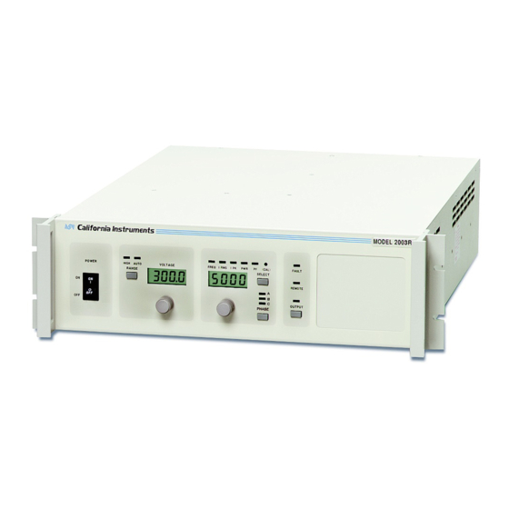
Model 2003RP
AC Power Source
User and Programming
Manual
Contact Information
Telephone: 800 733 5427 (toll free in North America)
858 450 0085 (direct)
Fax: 858 458 0267
Email:
Domestic Sales: domorders.sd@ametek.com
International Sales: intlorders.sd@ametek.com
Customer Service: service.ppd@ametek.com
Web:
www.programmablepower.com
March 2011
Document No. 4005-995 Rev N
Advertisement
Table of Contents
Troubleshooting

Subscribe to Our Youtube Channel
Related Manuals for Ametek 2003RP


Summary of Contents for Ametek 2003RP
- Page 1 Model 2003RP AC Power Source User and Programming Manual Contact Information Telephone: 800 733 5427 (toll free in North America) 858 450 0085 (direct) Fax: 858 458 0267 Email: Domestic Sales: domorders.sd@ametek.com International Sales: intlorders.sd@ametek.com Customer Service: service.ppd@ametek.com Web: www.programmablepower.com March 2011 Document No.
-
Page 3: Contact Information
About AMETEK AMETEK Programmable Power, Inc., a Division of AMETEK, Inc., is a global leader in the design and manufacture of precision, programmable power supplies for R&D, test and measurement, process control, power bus simulation and power conditioning applications across diverse industrial segments. - Page 4 This page intentionally left blank.
-
Page 5: Important Safety Instructions
Neither AMETEK Programmable Power Inc., San Diego, California, USA, nor any of the subsidiary sales organizations can accept any responsibility for personnel, material or inconsequential injury, loss or damage that results from improper use of the equipment and accessories. - Page 6 AMETEK will, at its expense, deliver the repaired or replaced Product or parts to the Buyer. Any warranty of AMETEK will not apply if the Buyer is in default under the Purchase Order Agreement or where the Product or any part...
-
Page 7: Table Of Contents
Table of Contents Introduction............................. 1 General Description ..........................1 Accessory Equipment/Rack Slides ......................1 Specifications ..........................2 Electrical ..............................2 Supplemental............................5 Measurements [Option] ......................... 6 System Specification ..........................7 Unit Protection ............................8 Mechanical ............................8 Environmental ............................9 Regulatory ............................. - Page 8 Service ............................52 General ............................... 52 Cleaning .............................. 52 Basic Operation........................... 52 Module Removal ..........................55 Replaceable Parts ..........................58 Remote Control ..........................60 Introduction ............................60 PGUI32 Program Requirements ......................60 IEEE Interface ............................. 62 RS232C Interface ..........................63 PGUI32 Setup and Installation ......................
- Page 9 Figure 2-1: Available RMS Current as function of Output Voltage and Frequency......4 Figure 2-2: Rack Mount Slides (-RMS option) position ............... 11 Figure 3-1: Model 2003RP AC Power Source ..................12 Figure 3-2: Rear Panel View ......................13 Figure 3-3: Internal Jumper Location, Input Line Voltage 107/115 ............
- Page 10 List of Tables Table 1-1: Available models ........................1 Table 3-1: Maximum Output Wiring Lengths ..................19 Table 4-1: Factory Default Power on Settings ..................31 Table 6-1: Load Resistors and Current ....................42 Table 6-2: CAL Mode Status LED Indicators ..................43 Table 7-1: Basic Symptoms .......................
-
Page 11: Introduction
1.2 Accessory Equipment/Rack Slides General Devices Company Model C300S-120-B308 rack slides may be attached to the sides of the power source using 10-32 X 3/8 flat head screws. 2003RP-AV models may be factory configured with a single voltage range and fixed frequency output. -
Page 12: Specifications
Parameter Specification Outputs Phases: Mode: Coupling: Voltage 2003RP: 0 to 135 V or 0 to 270 V (see Section 3.7) 2003RP-AV: 0 to 115 V or 0 to 230 V 0 to 115 V only (factory set) 2003RP-HV: 0 to 156 V or 0 to 312 V (see Section 3.7) - Page 13 ± 0.015% of full scale under constant load, line and (24 hours) temperature Total Power: 2000 VA maximum at full scale voltage, either range Current per Output Phase Volt Range PEAK 2003RP: 15.0 2003RP-AV: 17.6 2003RP-HV 12.9 Adjustable Limit: 0.0 to Maximum available RMS current for selected voltage range.
-
Page 14: Figure 2-1: Available Rms Current As Function Of Output Voltage And Frequency
Parameter Specification Frequency 2003RP: 16.0 - 5000 Hz (see Figure 2-1) 2003RP-HV: Maximum output voltage available from 45 Hz and up. Maximum voltage derates from 100% at 45 Hz to 35% at 16 Hz. 2003RP-AV: 360.0 - 5000 Hz (see Figure 2-1) Resolution: 0.01 Hz from 16.00 to 80.00 Hz... -
Page 15: Supplemental
Supplemental Note: Specifications listed below are typical and not guaranteed. Parameter Supplemental Specification Line Frequency: 63 - 300 Hz (derate maximum output power 5%) 300 - 440 Hz (derate maximum output power 10%) Output Voltage Accuracy ± 1% of full scale (2000 - 4000 Hz), (versus output frequency): ±... -
Page 16: Measurements [Option]
2.3 Measurements [Option] Note: Specifications listed below apply from 300 Hz to 500 Hz. Refer to Supplemental Specifications for frequencies outside this range. Parameter Specification Unit True RMS Current Available on standard unit. Ranges 0.000 - 4.000 0.00 – 6.00 Accuracy 0.2 % FS + 0.3 % reading Resolution... -
Page 17: System Specification
Parameter Specification Unit Power Factor Range 0.00 - 1.00 Accuracy 0.05 Resolution 0.01 2.4 System Specification Parameter Specification Setup storage Eight non-volatile front panel setup registers available through interface. Power-on setting register available from front panel. Interface (Option package -OP1 required) RS-232C Bi-directional serial interface Handshake:... -
Page 18: Unit Protection
Width Depth Unit 13.26 48.26 56.62 5.22 22.29 inch Unit Weight: 2003RP 39 kg / 85 lb 2003RP-AV 34 kg / 76 lb Material: Steel chassis and panels Aluminum cover Finish: Painted semi-gloss polyurethane Cooling: Fan cooled with air intake on sides and exhaust to rear... -
Page 19: Environmental
2.7 Environmental Parameter Specification Operating Temp: 0 to +40 C Storage Temp: -40 to +85 C Humidity: Maximum relative humidity 80% for temperatures up to 31 C decreasing linearly to 50% relative humidity at 40 C 2000 m maximum Altitude: Pollution Degree: Installation Category (Overvoltage Category) :... -
Page 20: Front Panel Controls
2.9 Front Panel Controls Parameter Specification Controls: Knobs: Two knobs allow continuous change of voltage, frequency and current limit for all three phase outputs. Voltage change is inactive on single voltage range configuration units. Function keys: Keys control output state, voltage range, 7 segment LED Display mode and selected phase for liquid crystal display. -
Page 21: Available Options
/ 74.3 mm above the bottom edge of the front panel. Note: The 2003RP series models cannot be mounted in a cabinet by just using the front panel rack ears. They require additional support. Figure 2-2: Rack Mount Slides (-RMS option) position Additional options may have been made available since this manual revision. -
Page 22: Installation And Functional Test
The AC Power System has been designed to operate from a single phase AC line voltage. The nominal operating voltage is either 107/115V or 208/230V line input. The 2003RP line input setting is shown on the type label located on the rear panel. -
Page 23: Figure 3-2: Rear Panel View
3.2.1 AC Line Voltage The AC Power Source has been designed to operate from either of the following AC line voltage ranges: 1) 107/115 volts 2) 208/230 volts CAUTION: The AC Power Source will be damaged if it is operated at an input voltage that is outside its configured input range. -
Page 24: Input Voltage Range Selection
3.3 Input Voltage Range Selection WARNING: Voltages up to 360 VDC and 270 VAC are present in certain sections of this power source. This equipment generates potentially lethal voltages. DEATH: On contact may result if personnel fail to observe safety precautions. Do not touch electric circuits when power is applied. - Page 25 3.3.1 Low Input Voltage Range Configuration (107/115 V) In order to change the voltage range configuration: 1. Turn off the input circuit breaker. 2. Disconnect AC input power by unplugging the power cord. 3. Remove the AC Power Source top cover by removing (17) #6-32 x 5/16” FLH screws. There are a total of 7 screws on the sides and 10 screws on the top that hold the cover.
- Page 26 3.3.2 High Input Voltage Range Configuration (208/230 V) In order to change the voltage range configuration: 1. Turn off the input circuit breaker. 2. Disconnect AC input power at TB1. 3. Remove the AC Power Source top cover by removing (17) #6-32 x 5/16” FLH screws. There are a total of 7 screws on the sides and 10 screws on the top that hold the cover.
-
Page 27: Mechanical Installation
/ 74.3 mm above the bottom edge of the front panel. Note: The 2003RP series models cannot be mounted in a cabinet by just using the front panel rack ears. They require additional support. Figure 3-5: Rack Mount Slides (-RMS option) position 3.5 Input Wiring... -
Page 28: Output Connections
Because of the possibility of hazardous voltages on the output terminals, insulation of wiring on the output must be rated for the maximum output voltage of the source, at least 270 volts. There must be no accessible live part connected to the 2003RP output terminals. See Figure 3-6. -
Page 29: Figure 3-6: Input And Output Wiring
Table 3-1: Maximum Output Wiring Lengths The Remote Sense inputs must be connected or an output voltage 7% higher than the programmed output will be generated. If the 2003RP is configured for constant voltage, a fault will be generated. AC Input... -
Page 30: Output Voltage Ranges
If this is not acceptable, the AC source should be operated in the high voltage range only and not in AUTO mode. 2003RP-AV units can be factory configured for single voltage range. In this case, the high voltage range is not present. -
Page 31: Functional Test
Model Voltage Range Resistor Current (A 2003RP 2003RP-AV 230 (if configured) 2003RP 1. One phase at a time, connect a voltmeter and an oscilloscope or distortion analyzer to the AC source output at the rear panel output terminals. Connect each sense input to the adjacent power pin on the rear panel connector. -
Page 32: Other Modes Of Operation
Figure 3-7: Test Setup 2003RP. 3.9 Other Modes of Operation When the 2003RP is shipped from the factory, it is configured for the Constant Current Mode of operation. This mode means that if the load current exceeds the programmed Current Limit value, the output voltage will drop and the current will continue at the programmed value. -
Page 33: Front Panel Operation
Front Panel Operation 4.1 Functional Controls The front panel can be divided in a small number of functional areas: Status Indicator lights Control knobs LED displays Control buttons Figure 4-1: Front Panel View... - Page 34 The output relay state is not changed however. RANGE - AUTO The RANGE AUTO LED indicates the 2003RP is in auto ranging mode and will switch voltage range automatically if the selected output voltage increments or decrements through the low range voltage limit.
-
Page 35: Figure 4-2: Voltage Auto Range Switch Over Points
Illuminates when the 7 segment LED display shows the measured power factor. It also illuminates in the calibration mode of operation. In calibration mode, the PF LED is always lit in combination with the measurement or output function being calibrated. In normal mode of operation, only one LED in this group is on at a time. -
Page 36: Figure 4-3: Control Knob
2003RP-AV is configured for a single voltage range, this button is disabled. The same button may be used to put the 2003RP in the AUTO voltage range change mode. This button toggles from Lo, Auto, Hi and back to Lo. The AUTO LED will illuminate when the AUTO range mode is enabled. - Page 37 The SELECT button will define the operating mode or the selected measurement parameter for the right hand display. The PHASE button selects the output phase. Note that older model 2003RP power sources may have LCD displays instead of LED displays. Operation of both versions is identical.
-
Page 38: How To Examples
4.2 How to examples... This section covers some common tasks that are often performed with an AC power source. These examples are written in a “How to...” format and provide step by step instructions on how to set up the AC Source for specific tasks. 4.2.1 Set the Output Output parameters are Voltage, Frequency and Current Limit. - Page 39 Note: For peak current, power and power factor measurements, Option -OP1 is required. 4.2.4 Change the Voltage Range The voltage range can be changed as follows (if the 2003RP-AV is configured for a single voltage range, this does not apply): 1.
- Page 40 4.2.6 Measure Peak Inrush Current (Requires -OP1 Option) The peak current measurement function of the 2003RP uses a sample and hold circuit to track the highest peak current found until reset. The peak current sample and hold circuit is reset any time the user toggles away from the peak current display mode to a different measurement.
-
Page 41: Setting The Power On Initialization Values
4.3 Setting the Power on Initialization Values The 2003RP is supplied with default factory settings when the unit is powered up. The factory settings are: Parameter Factory default setting Voltage range Auto Voltage Range Voltage 5.0 Volt Frequency 60 Hz ( 400 Hz on 2003RP-AV models) Current limit 5.0 amps (5.9 amps on 2003RP-AV models, 4.3 amps... -
Page 42: Current Limit Modes
4.4 Current Limit Modes The 2003RP supports two modes of current limiting. In either mode, the user can set the RMS current level at which the current limit function will operate. The available current limit modes are: Constant Current (CC) mode This is the default mode as supplied from the factory. -
Page 43: Remote Inhibit [Option]
4.6 Remote Inhibit [Option] A Remote Inhibit BNC input is located on the rear panel of the 2003RP if the -OP1 option was specified at the time of purchase. This input may be used to disable the AC source output using an external control signal. -
Page 44: Principle Of Operation
This assembly is identified as A4. It generates the high power +300 VDC supply used by the amplifiers. The DC supply also has circuits that generate auxiliary DC voltages for the low power circuits of the 2003RP: 1. +26V (output referred) supply for relays and fans. 2. +18V, -18V (output referred) supply for oscillator control circuits 3. -
Page 45: Figure 5-1: Ac Power System Block Diagram
GPIB RS232 RS232/ PHASE B/C CONTROLLER AMPLIFIER A AMPLIFIER B AMPLIFIER C GPIB Remote Inhibit Function Strobe MOTHER BOARD E4 E3 E6 E5 E8 E7 +300 COM2 E1 E2 E3 E4 E5 E6 T B2 DC SUPPLY RANGE/RELAY OUTPUT P7 J7 EMI FILTER Bridge T B1... -
Page 47: Mother Board
5.4 Mother Board The Mother board, module assembly A5, routes signals between the various assemblies in the power source. The Mother board also has circuits that scale the oscillator reference waveforms for the two different voltage ranges. The oscillator reference waveforms are also adjusted via potentiometers: 1. -
Page 48: Output Board
The voltage is monitored internally if the output relay is open. 5.9 IEEE 488/RS232 Interface [Option] The 2003RP can optionally be fitted with a combined RS232C and IEEE 488 interface board, A3. This board assembly has optocouplers for isolation of the programming interface and the Remote Inhibit and Function Strobe connections. - Page 49 CAUTION VOLTAGES UP TO 300 V AND 400 V ARE PRESENT IN CERTAIN SECTIONS OF THIS POWER SOURCE. THIS EQUIPMENT GENERATES POTENTIALLY LETHAL VOLTAGES. DEATH ON CONTACT MAY RESULT IF PERSONNEL FAIL TO OBSERVE SAFETY PRECAUTIONS. DO NOT TOUCH ELECTRONIC CIRCUITS WHEN POWER IS APPLIED.
-
Page 50: Calibration
230 V 2.9 A 2003RP-HV 156 V 4.3 A 312 V 2.16 A Table 6-1: Load Resistors and Current Some 2003RP-AV may be factory configured for single voltage range only. In this case, the 230 V range is not available. -
Page 51: Selecting Calibration Mode
Briefly pressing this button will place the 2003RP in CAL mode, indicated by the illumination of the PF LED. While in CAL mode, the front panel controls are used to adjust the various calibration parameters. -
Page 52: Routine Calibration
Figure 6-1: Test Equipment Hookup for Routine Output and Voltage Measurement Calibration 6.3.1 Output Voltage Calibration 1. Select the high voltage range. Set the output frequency to 60 Hz (400 Hz on 2003RP- AV). Set the output voltage to 230 volts. -
Page 53: Figure 6-2: Test Equipment Hook-Up For Current And Power Measurement Calibration
2. Select the Low Voltage Range and program the output voltage to 10 VAC. 3. Put the 2003RP in CAL mode by pressing the recessed CAL button. 4. Use the SELECT key to select the Voltage Measurement calibration mode. This mode is indicated by the FREQ LED. - Page 54 measuring the current shunt voltage (DMM 1). Note that 0.1 V reading represents 1 Amp if the recommended 100 m shunt is used. Low Scale Peak Current Measurement Calibration 1. Connect the test equipment to the power source as shown in Figure 6-2. 2.
- Page 55 2. Select the High Voltage Range and program the output voltage to 230.0 VAC. 3. Put the 2003RP in CAL mode by pressing the recessed CAL button. 4. Use the SELECT key to select the Voltage Measurement calibration mode. This mode is indicated by the FREQ LED.
-
Page 56: Non-Routine Calibration
Full Scale Power Measurement Calibration 1. Connect the test equipment to the power source as shown in Figure 6-2. 2. Apply the resistive load (see Table 6-1 for model and load) to the output terminals. Set the power source to low voltage range. 3. - Page 57 2. Program the current to 4.5 amps. Program the output to 135 V (115 V for the –AV option, 156V and 3.9 amps for 2003RP-HV, adjust for 4.1 in step 3) on the low voltage range and 400 Hz.
-
Page 58: Figure 6-3: Internal Adjustments
Figure 6-3: Internal Adjustments... - Page 59 Connect the test equipment as shown in Figure 6-1. NOTE: The 2003RP must be configured for the Constant Current Mode of operation for this procedure. For this mode jumpers W1 and W2 on the Controller board and W1, W3, W4, and W6 on the Phase B/C board must be removed.
-
Page 60: Service
Service 7.1 General This section describes suggested maintenance and troubleshooting procedures. The troubleshooting procedure is divided into two sections. The first section deals with basic operation and connection of the equipment. The second section requires opening the unit and using the LED indicators and a simple multimeter to troubleshoot the unit down to the module level. -
Page 61: Table 7-3: Poor Output Voltage Regulation
7.3.2 Poor Output Voltage Regulation If the AC Power Source exhibits poor voltage regulation the following item may be at fault: Table 7-3: Poor Output Voltage Regulation CAUSE SOLUTION The Remote Sense lines are not Connect AC voltmeter to Remote Sense connected at the same point monitored by lines on the Rear Panel Power Output the external voltmeter used for load... -
Page 62: Table 7-7: No Output But "Display" Is On
Fan not working. Replace fan. Consult factory. If the 2003RP is configured to operate in the Constant Voltage mode, the Fault lamp comes on when the output load current has exceeded the programmed current limit value. If the AC Power Source Fault lamp is on, the following items may be at fault:... -
Page 63: Module Removal
7.3.8 Can’t Program AC Power System on GPIB or RS232 If the power source does not respond to GPIB or RS232 programming, the following items may be at fault: CAUSE SOLUTION The power source unit address is Set correct address. See section 8.3. incorrect. -
Page 64: Figure 7-1: Assembly Location
Figure 7-1: Assembly Location... - Page 65 7.4.1 Oscillator Module Removal/Replacement If a fault is found that requires the replacement of the Oscillator Module (assemblies A2 and A3) follow the following steps and refer to Figure 7-1 for the module locations: 1. Turn off the front panel circuit breaker. Remove the input power from the rear panel terminal block.
-
Page 66: Replaceable Parts
4005-723-1 PC Assy, Output/Sense 16067 Fan, 4”, 24VDC 241182 77062 OUTPUT TRANSFORMERS, T1, T2, T3 T1, T2, T3 4008-024-1 Output Transformer, 2003RP T1, T2, T3 4008-028-1 Output Transformer, 2003RP-AV T1, T2, T3 4008-021-1 Output Transformer, 2003RP-HV Table 7-8: Replaceable Parts... -
Page 67: Table 7-9: Fuses
SEQ# C.I.PART # DESCRIPTION VENDOR DC SUPPLY, A4 270176 20A, 250V, quick acting (Bussmann ABC20) 71400 270174 1A, 250V, very quick acting (Bussmann, PCC1) 71400 MOTHER BOARD, A5 270209 5A, 250V, quick acting (Littelfuse, 312005) 75915 270209 5A, 250V, quick acting (Littelfuse, 312005) 75915 270209 5A, 250V, quick acting (Littelfuse, 312005) -
Page 68: Remote Control
Remote Control 8.1 Introduction The 2003RP can be furnished with a combination IEEE-488 and RS232C control interface at the time of purchase. This interface is part of the -OP1 option package. The interface option also includes the California Instruments Graphical User Interface program - PGUI32. This Windows™... -
Page 69: Figure 8-1: Rear Panel View
Figure 8-1: Rear Panel View... -
Page 70: Ieee Interface
Figure 8-1 for the location of this switch. The IEEE address of the 2003RP is set using the DIP switch at the rear of the unit. Switch position 4 through 0 corresponds to bits 4 through 0 of the IEEE address. See figure below. -
Page 71: Rs232C Interface
8.4 RS232C Interface A suitable cable to connect the 2003RP AC Source to a 9 pin PC-AT style serial port is supplied with the source. If you are unable to locate this cable, you need to use a cable that conforms to the wiring diagram shown in Figure 8-3. - Page 72 END IF IF esr% AND 8 THEN PRINT "*** Instrument Dependent Error Reported by AC Source ***" END IF IF esr% AND 16 THEN PRINT "*** Command Execution Error Reported by AC Source ***" END IF IF esr% AND 32 THEN PRINT "*** Command Syntax Error Reported by AC Source ***"...
-
Page 73: Pgui32 Setup And Installation
8.5.1 Connecting the AC Source to the PC When Using RS232 Connect the AC source to the PC using an RS232C cable. Set the AC source COM port settings as follows: Baud rate: 19200 baud for model 2003RP Data bits: Stop bits Parity bits:... - Page 74 8.5.2 Connecting the AC Source to the PC Using IEEE-488 Connect the AC source to the PC using an IEEE-488 interface cable. A National Instruments GPIB controller card is required to use the PGUI32 program. Select the IEEE-488 interface by sliding the interface selection dip switch on the rear panel to the IEEE-488 position.
-
Page 75: Troubleshooting - Rs232C
8.6 Troubleshooting - RS232C This section provides guidelines for resolving communication problems that may occur when using the PGUI32 software under Windows . You may encounter problems when using the serial interface with the PGUI32 program that is supplied with the interface option for this source. Symptoms: 1. -
Page 76: Figure 8-4: System Properties Dialog Box
Procedure 1. Make sure the PGUI32 program is closed and no device is using the COM port in use. desktop, right click on the “My 2. From the Windows Computer” icon which is located in the top left corner of the screen. 3. - Page 77 Resolution for Symptom 2 Execute the suggested procedure to resolve symptom 1 first. If an occasional error continues to occur while slewing the voltage or frequency slider controls in the PGUI32 program, add a command delay to the PGUI32 Registry Interface section using the following procedure.
-
Page 78: Troubleshooting - Ieee-488 / Gpib
AC source. Things to check first: 1. Is the 2003RP interface option set to use the IEEE-488 interface instead of the RS232C interface? The DIP switch on the rear panel is used to select the desired interface mode. - Page 79 Resolution for Symptom 2 The 2003RP has a limit on how fast it can process commands sent over the bus. When developing an application program that controls the 2001RP AC source, this must be considered. Specifically, if non-query commands (commands that don‟t wait for a response such as output setup commands) are sent at too high a rate, the AC source may not be able to process them.
-
Page 80: Pgui32 Distribution Files
8.8 PGUI32 Distribution Files The installation program will install the following files in the directories specified. Note that files with the same name that already exists in these directories will not be overwritten as part of the installation process. If older files of the same name are found, they will be replaced. If you need to retain a copy of these older version files, we recommend you back these files up prior to running the installation program. -
Page 81: Software Registration
Test Sequence Program Directory Files File name Description Sample sequence test file.SEQ Sample output sequence file Note: The location of these files as well as the files themselves may change with future versions of the PGUI32. Consult the included readme file for last minute program information. -
Page 82: Introduction To Scpi
Introduction to SCPI SCPI (Standard Commands for Programmable Instruments) is a programming language for controlling instrument functions over the RS232 or IEEE 488 bus. The same SCPI commands and parameters control the same functions in different classes of instruments. For example, you would use the same MEAS:VOLT? command to measure the AC source output voltage or the output voltage of a SCPI-compatible Multimeter. -
Page 83: Figure 9-1: Partial Command Tree
The SCPI Command Tree As previously explained, the basic SCPI communication method involves sending one or more properly formatted commands from the SCPI command tree to the instrument as program messages. The following figure shows a portion of a subsystem command tree, from which you access the commands located along the various paths (you can see the complete tree in appendix A). -
Page 84: Using Queries
The message terminator after LEVel 115 returns the path to the root. Note: The 2003RP interface buffer is limited to 45 characters + [LF]. As such, compound commands should be used with care to make sure they do not exceed this message length limit. -
Page 85: Figure 9-2: Command Message Structure
Combining Message Units The following command message is briefly described here, with details in subsequent paragraphs. Data Query Indicator Message Unit Header SOUR:VOLT 80; FREQ 60; :CURR? <NL> Header Message Root Message Separator Unit Specifier Terminator Separator Figure 9-2: Command Message Structure The basic parts of the above message are: Message Component Example... - Page 86 Header Convention In the command descriptions in chapter 10 of this manual, headers are emphasized with boldface type. The proper short form is shown in upper-case letters, such as DELay. Header Separator If a command has more than one header, you must separate them with a colon (SYSTem:ERRor LIMit:FREQuency:LOW).
-
Page 87: Scpi Data Formats
9.5 SCPI Data Formats All data programmed to or returned from the AC source is in ASCII. The data type may be numerical or character string. Numerical Data Formats Symbol Data Form Talking Formats <NR1> Digits with an implied decimal point assumed at the right of the least- significant digit. -
Page 88: Scpi Command Reference
10 SCPI Command Reference Where appropriate, related commands or queries are included. These are listed because they are either directly related by function, or because reading about them will clarify or enhance your understanding of the original command or query. This chapter is organized as follows: Subsystem commands, arranged by subsystem IEEE 488.2 common commands... -
Page 89: Calibration Subsystem
10.2 Calibration Subsystem The commands in this subsystem allow you to do the following: Enable and disable the calibration mode Calibrate all measurement circuits and store new calibration coefficients in nonvolatile memory. Subsystem Syntax CALibrate :STATe Enables or disables the calibration mode :MEASure :CURRent [:FSC]... - Page 90 10.2.2 Measurement Calibration All measurement calibrations are performed by adjusting the measurement reading up or down using a calibration coefficient. The coefficient value ranges from -127 (adjust full-scale downward, zero upward) to + 127 (adjust full-scale upward, zero downward). When used in combination with the MEAS commands, an automated measurement calibration procedure can be implemented by adjusting the coefficient and reading the new measurement value iteratively until the delta between an external reference measurement device and the AC...
- Page 91 CALibrate:MEASure:POWer[:FSCale] <NRf> This command affects the calibration of the power measurement at full scale. Command Syntax CALibrate:MEASure:POWer[:FSCale] <NRf> Parameters <NRf> (value range -127 to +127) Examples CAL:MEAS:POW 78 Query Syntax CALibrate:MEASure:POWer? Returned Parameters <NR1> (value range -127 to +127) Related Commands CALibrate:MEASure:CURRent CALibrate:MEASure:POWer:ZERO <NRf>...
- Page 92 10.2.3 Output Calibration The AC voltage output calibration is performed by adjusting the output up or down using a calibration coefficient. The coefficient ranges from -127 (adjust upward) to + 127 (adjust downward). An external traceable reference AC voltmeter should be used for this purpose. CALibrate[:SOURce]:VOLTage <NRf>...
-
Page 93: Measurement Subsystem
10.3 Measurement Subsystem This subsystem programs the measurement capability of the RP Series AC source. To select the desired phase, use the INST:NSEL command before the measurement command. Once selected, a phase selection remains in effect until the next INST:NSEL command. Subsystem Syntax :MEASure :VOLTage? - Page 94 MEASure:CURRent:AMPLitude:MAX? This query returns the peak value of the output AC current being sourced at the output terminals. Note that the output relay must be closed to obtain current flow. The peak current measurement circuit uses a sample and hold method and latches the highest peak current value found since the last peak measurement reset command.
- Page 95 MEASure:POWer[:REAL]? This query returns the true power delivered to the unit under test by the AC source. Note that the output relay must be closed to obtain current flow. Query Syntax MEASure:POWer[:REAL]? Parameters None Examples MEAS:POW? Returned Parameters <NR2> Related Commands MEAS:VOLT? MEAS:CURR? MEASure:POWer:APParent? This query returns the apparent power delivered to the unit under test by the AC source.
-
Page 96: Instrument Subsystem
This command may be used to couple all output phases in three phase mode. For the 2003RP, this command only applies to the OUTPut:DROP command. When the phases are coupled, the OUTP:DROP command affects all three phases. This allows the output voltage to be dropped for all three phases using a single command and without the need to select each phase individually. -
Page 97: Source Subsystem
10.5 Source Subsystem This subsystem programs all the output parameters of the RP Series AC source. Subsystem Syntax [SOURce:] CURRent: Set the rms current limit in amps. VOLTage: [LEVel] Set the rms output voltage value in volts. RANGe: [LEVel] Set the output voltage range. AUTO Enables or disables the AUTO range mode. - Page 98 [SOURce:]VOLTage This command programs the AC rms output voltage level of the power source. The maximum voltage value allowed is determined by the selected voltage range. For 2003RP- AV models configured for single voltage range, only one range is available.
- Page 99 This command sets the voltage range of the power source. Two voltage ranges are available: a 135 volt range and a 270 volt range. However, 2003RP units with optional voltage ranges (2003RP-HV) are available as well. In this case, the actual voltage range values will be different.
-
Page 100: Output Subsystem
To determine the actual voltage range in which the unit is operating, the VOLT:RANG? command query can be used. For 2003RP-AV models configured for single voltage range, only one range is available. In this case, the VOLT:RANGe:AUTO command has no meaning and should not be used. - Page 101 OUTPut:DROP The output drop command may be used to interrupt the voltage to the UUT without opening the output relay. This method uses an electronic means of interrupting the AC source output which enables short interruptions of as little as 1 ms or as long as 4000 s. In addition to short interruption times, the drop command can be set to use any of four start phase angles at which to execute the voltage drop.
- Page 102 Example: Individual Phase Loss Test The following command sequence will drop the output of phase A only for 10 cycles at 400 /* Set up sequence VOLT 115;FREQ 400 Set output voltage to 115 V at 400 Hz (all phases) INST:COUP 0 Uncouple output phases INST:NSEL 1...
- Page 103 OUTPut: STARt[:STATe] The output start state command is used to enable or disable the start phase logic of the AC source controller. If disabled (State = 0), any voltage drops with the OUTP:DROP command or voltage changes with the VOLT command are executed immediately without regard for the phase angle of the output sinewave.
-
Page 104: Limit Subsystem
<NR2> LIMit:FREQuency:LOW? This command queries the lower frequency limit of the power source. On the 2003RP-AV, the frequency range may have been factory configured to a fixed single value. In this case, the High and Low frequency limits will be set to the same value and both queries will return the same number. -
Page 105: Display Subsystem
If the voltage limit value is less than 201 volt, the 2003RP is configured for single voltage range operation. If a value above 200 volt is returned, the 2003RP has a high and a low voltage range. On dual range configurations, the maximum voltage in the high range is returned and this value must be even. -
Page 106: System Commands
10.9 System Commands The system commands control the system level functions of the AC Source. Subsystem Syntax SYSTem: ERRor? Returns the error number and error string KLOCk Keyboard Lock. Sets the power on REMOTE/LOCAL state. LOCal Go to local mode Define the power on register number REMote Go to remote mode... - Page 107 SYSTem:REMote This command sets the interface in the Remote state, which disables all front panel controls. This command only applies to the RS232C interface. If IEEE 488 is used, the remote/local status is determined by the REN line on the IEEE 488 interface. Command Syntax SYSTem:REMote Parameters...
-
Page 108: Common Commands
10.10 Common Commands Common commands begin with an * and consist of three letters (command) or three letters and a ? (query). Common commands are defined by the IEEE 488.2 standard to perform some common interface functions. The power source responds to the required common commands that control status reporting, synchronization, and internal operations. -
Page 109: Table 10-2: Bit Configuration Of Standard Event Status Enable Register
10.10.1 *CLS This command clears the following registers (see chapter 12 for descriptions of all status registers): Standard Event Status Status Byte Error Queue Command Syntax *CLS Parameters None 10.10.2 *ESE This command programs the Standard Event Status Enable register bits. The programming determines which events of the Standard Event Status Event register (see *ESR?) are allowed to set the ESB (Event Summary Bit) of the Status Byte register. -
Page 110: Table 10-3: Bit Configuration Of Standard Event Status Register
10.10.3 *ESR? This query reads the Standard Event Status register. Reading the register clears it. The bit configuration of this register is the same as the Standard Event Status Enable register (see *ESE). Query Syntax *ESR? Parameters None Returned Parameters <NR1>(Register value) Related Commands *CLS... - Page 111 Revision level of firmware Example "CI,2003RP,12345,Rev 1.0" The following table shows the series of queries that may be used to detect the presence of a 2003RP or a 2003RP-AV and to determine the frequency range setting of a 2003RP-AV: Step Query command Response...
-
Page 112: Table 10-4: *Rst Default Parameter Values
10.10.6 *RST This command resets the AC source to a setting defined by the values in the register defined by PON if valid or by the following factory-defined states: Table 10-4: *RST Default Parameter Values Item Value Item Value VOLT 5.0 V FREQ 60 Hz... -
Page 113: Table 10-6: Bit Configuration Of Status Byte Register
10.10.7 *SAV This command stores the present state of the AC source to a specified location in memory. The RP Series offers eight non-volatile memory locations for storing instrument setups. Command Syntax *SAV Parameters 0 through 7 Related Commands *RCL *RST 10.10.8 *SRE... -
Page 114: Programming Examples
11.2 Bus Throughput and Timing Considerations The 2003RP has a limit on how fast it can process commands sent over the bus. When developing an application program that controls the 2003RP AC source, this must be considered. - Page 115 Programming the Output Power-on Initialization When the AC source is first turned on, it wakes up with the output state defined by the PON register number. If the register number or the register has no valid data, the AC source initializes to the following state.
-
Page 116: Making Measurements
Turning on output voltage for all three phases at a specified phase angle The following command sequence will turn the output voltage on at a specified phase angle. This may be required to measure worst case inrush current. /* Set up sequence VOLT 0 Set output voltage to zero OUTP 1... - Page 117 To measure the RMS current, use: MEAS:CURR? To measure the peak current, use: MEAS:CURR:AMPL:RES /* resets track and hold for peak curr. meas. /* It may be need to turn the output on or program /* as specific voltage at this time before taking a /* peak current reading.
-
Page 118: Status Registers
12 Status Registers You can use status register programming to determine the operating condition of the AC source at any time. For example, you may program the AC source to generate an MSS bit when an event such as a current limit occurs. When the MSS bit is set, your program can then act on the event in the appropriate fashion. -
Page 119: Standard Event Status Group
12.2 Standard Event Status Group This group consists of an Event register and an Enable register that are programmed by Common commands. The Standard Event register latches events relating to interface communication status. It is a read-only register that is cleared when read. The Standard Event Enable register functions similarly to the enable registers of the Operation and Questionable status groups. -
Page 120: Examples
12.4 Examples The following section contains examples of commonly used operations involving the status registers. You can determine the reason for an MSS bit set by the following actions: Step 1 : Determine which summary bits are active. Use: *STB? Step 2 : Read the corresponding Event register for each summary bit to determine which events caused the summary bit to be set. -
Page 121: Appendix A: Scpi Command Tree
Appendix A: SCPI Command tree Command Syntax Tree Root Level 1 Level 2 Level 3 Level 4 CALibrate :STATe :MEASure :CURRent [:FSCale] :ZERO :PCURrent [:FSCale] :ZERO :POWer [:FSCale] :ZERO :VOLTage [:FSCale] :ZERO [:SOURce]:VOLTage INSTrument :COUPling :NSELect [SOURce] :CURRent :FREQuency :VOLTage [:LEVel] :RANGe OUTPut... -
Page 122: Appendix B: Scpi Conformance Information
User and Programming Manual - Rev N California Instruments Appendix B: SCPI Conformance Information SCPI Version The RP Series AC power sources conform to SCPI version 1990.0. March 2011 2003RP... -
Page 123: Appendix C: Error Messages
User and Programming Manual – Rev N California Instruments Appendix C: Error Messages Error Number Error Message String Error Causes "No error" -100 "Command error" Generally the result of sending a command that uses incorrect syntax. This same error may result from the inability of the AC source to process successive GPIB non-query commands sent to it. -
Page 124: Index
CALibrate:MEASure:PCURrent:ZERO ..82 specification ..........4 CALibrate:MEASure:PCURrent[ FREQuency ............ 90 FSCale] ............82 frequency range CALibrate:MEASure:POWer:ZERO ....83 2003RP-AV ..........96 CALibrate:MEASure:POWer[ fixed ............. 96 FSCale] ............83 front panel ..........23, 60 CALibrate:MEASure:VOLTage:ZERO ..83 lock .............. 24 CALibrate:MEASure:VOLTage[ Function Strobe .......... - Page 125 User and Programming Manual – Rev N California Instruments software ............66 INSTrument:COUPle ........88 PGUI32 ............60 INSTrument:NSELect ........88 Pollution Degree..........9 Insulation ............9 Introduction ............1 Isolation Voltage ..........2 queries ............76 keyboard RCL ............... 103 lock out............
- Page 126 Transients single ............97 Input ............... 8 voltage ranges ..........20 troubleshooting ..........52 VOLTage:RANGe:AUTO ........ 92 VOLTage:RANGe[:LEVel] ......91 Vibration ............9 Voltage Weight............... 8 specification ........... 2 wiring VOLTage ............90 input............. 17 voltage range March 2011 2003RP...
Need help?
Do you have a question about the 2003RP and is the answer not in the manual?
Questions and answers