
Subscribe to Our Youtube Channel
Related Manuals for Ametek XPD 7.5-67


Summary of Contents for Ametek XPD 7.5-67
-
Page 1: Power Supply
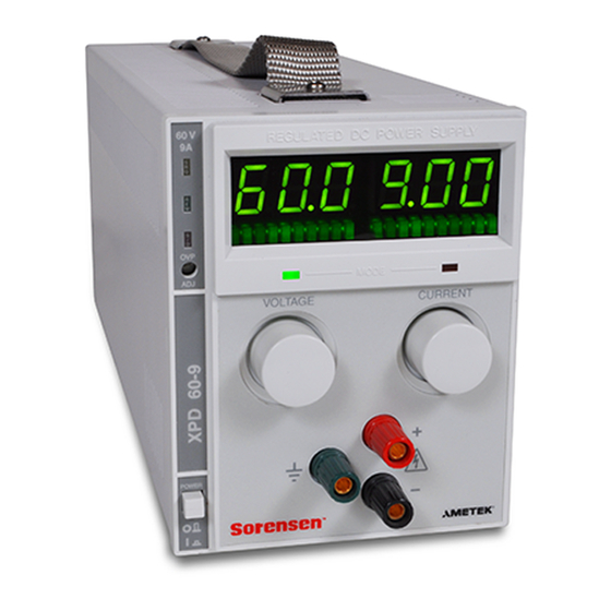
XPD Series Programmable DC Power Supply Operation Manual XPD 7.5-67 XPD 18-30 XPD 33-16 XPD 60-9 XPD 120-4.5 TM-PDOP-01XN Rev D www.programmablepower.com... -
Page 3: Contact Information
About AMETEK AMETEK Programmable Power, Inc., a Division of AMETEK, Inc., is a global leader in the design and manufacture of precision, programmable power supplies for R&D, test and measurement, process control, power bus simulation and power conditioning applications across diverse industrial segments. - Page 4 This page intentionally left blank.
-
Page 5: Important Safety Instructions
Neither AMETEK Programmable Power Inc., San Diego, California, USA, nor any of the subsidiary sales organizations can accept any responsibility for personnel, material or inconsequential injury, loss or damage that results from improper use of the equipment and accessories. - Page 6 This page intentionally left blank.
- Page 7 AMETEK will, at its expense, deliver the repaired or replaced Product or parts to the Buyer. Any warranty of AMETEK will not apply if the Buyer is in default under the Purchase Order Agreement or where the Product or any part...
- Page 8 This page intentionally left blank.
-
Page 9: About This Manual
About This Manual This Operating Manual contains operating information for the XPD Series of high-performance, switching, laboratory power supplies, available in several voltage models at 500 watts. It provides information on features and specifications, installation procedures, and basic functions testing, as well as operating procedures for using both front panel control and remote analog programming functions. - Page 10 About This Manual viii Operating Manual for XPD Series Power Supply...
-
Page 11: Table Of Contents
Contents About This Manual ........... vii Section 1. - Page 12 Section 3. Introduction ............35 Local Standard Operation .
-
Page 13: Description
Section 1. Features and Specifications Description Series of DC power supplies provides stable, variable output voltage and current for a broad range of development and system requirements. The units use high-frequency soft-switching technology to achieve high power density and retain a small package size. -
Page 14: Front Panel Controls
Section 1. Features and Specifications Front Panel Controls • This unit may be equipped with an optional internal GPIB or RS-232 control for remote digital programming and readback. • Remote output sensing provides load cable compensation up to 5 V/line (3 V/line for 7.5 V model). -
Page 15: Rear Panel Connectors
Section 1. Features and Specifications Rear Panel Connectors Rear Panel Connectors Remote Sensing Port: Remove Default Jumpers to Blank Sub-Plate: use Remote Sensing Replaced if Digital Programming Option is Installed Fan Exhaust Vents: Do not obstruct Analog Programming and Readback Busbar Cover Output Busbars IEC 320 AC Input... -
Page 16: Output Connectors
Section 1. Features and Specifications Rear Panel Connectors Output Low Voltage Models Equipped with positive and negative busbars. The busbars are offset to facilitate load cable connections. Connectors WARNING Disconnect the AC input before making any connections to the unit. Figure 1.4 Output Busbars - note polarity markings (Low Voltage Models) High Voltage Models High voltage models are equipped with a 4-terminal output... -
Page 17: Rear Panel J210 Connector
Section 1. Features and Specifications Rear Panel Connectors Rear Panel The J210 Analog Interface connector is a 15-pin female DSUB connector located on the rear panel. See Figure 1.6. Use the J210 programming, monitoring, and J210 shutdown 15 pin DSUB connector for remote programming and monitoring Connector functions. - Page 18 Section 1. Features and Specifications Rear Panel Connectors Table 1.2 Rear Panel J210 Connector Pins and Functions Reference Name Function J210-1 TTL S/D Shutdown Signal Return Return for shutdown signal (−) J210-2 TTL S/D Shutdown Input (+) Input for shutdown signal. J210-3 No connection None.
-
Page 19: Making J210 Connections
Section 1. Features and Specifications Rear Panel Connectors Making J210 Connections CAUTION Program/monitor signal and return are internally connected to the power supply negative output. Do not attempt to bias these away from that potential. CAUTION To maintain the isolation of the power supply output and prevent ground loops, use an isolated (ungrounded) programming source when operating the power supply via remote analog control at the J210 connector. -
Page 20: Electrical Specifications
Section 1. Features and Specifications Electrical Specifications Electrical Specifications These specifications are warranted over a temperature range of 0 °C to 50 °C with local sense. Above 50 °C, derate output linearly to zero at 70 °C. Nominal line voltages are 100/120/200/230/240 Vac. Specifications and characteristics refer to a single output model unless otherwise stated, and specifications apply to either front or rear outputs unless noted. -
Page 21: Additional Specifications
Section 1. Features and Specifications Additional Specifications 1. Front output current limited to 30 A maximum. 2. For input voltage variation over the AC input voltage range, with constant rated load. 3. For 0 to 100% load variation, with constant nominal line voltage (rear output only). 4. -
Page 22: Additional Characteristics
Section 1. Features and Specifications Additional Characteristics Additional Characteristics Over Temperature Protection (OTP) Unit latches off when T > rated maximum. Auto restart when cool OVP Control Adjustable on front panel single turn control. 110% setting 5% of rated output Switching Frequency 125 kHz (250 kHz output ripple) Output Hold-up Time... -
Page 23: Environmental Specifications
Section 1. Features and Specifications Environmental Specifications Environmental Specifications Operating Temperature Range 0 to 50 °C Storage Temperature Range -40 to 85 °C Humidity Range Up to 95% RH non-condensing Operating Altitude Maximum 6,500 feet (2,000 m) Derate maximum operating temperature by 1 °C per 1,000 feet (300 m) for operation between 5,000 feet (1500 m) and 6,500 feet (2,000 m) - Page 24 Section 1. Features and Specifications Mechanical Specifications Mounting Optional 19 in. (483 mm) rack mount kit (mounts 4 units). Maximum Dimensions Free standing: (single output) Height: 5.55 in. (140 mm) Width: 4.24 in (108 mm) Mounted: Height: 5.25 in.(133 mm) (3 U). Width: 1/4 rack (4 per 19 in.
-
Page 25: Introduction
Section 2. Installation Introduction This section provides recommendations and procedures for inspecting, installing, and testing the power supply. Basic Setup Procedure Table 2.1 for a summary of the basic setup procedure and a view of the subsections in this section. Use this procedure as a quick reference if you are unfamiliar with the installation requirements for the power supply. -
Page 26: Inspection, Cleaning, And Packaging
Section 2. Installation Inspection, Cleaning, and Packaging Inspection, Cleaning, and Packaging Initial When you first receive your unit, perform a quick physical check. Inspection 1. Inspect the unit for scratches and cracks in the chassis and front panel, and for broken switches, connectors, and displays. -
Page 27: Returning Power Supplies To The Manufacturer
Section 2. Installation Returning Power Supplies to the Manufacturer Returning Power Supplies to the Manufacturer Return Before returning a product directly to Xantrex you must obtain a Return Material Material Authorization (RMA) number and the correct factory “Ship To” address. Products must also be shipped prepaid. -
Page 28: Packaging For Shipping Or Storage
Section 2. Installation Returning Power Supplies to the Manufacturer Packaging for Follow these instructions to prepare the unit for shipping or storage. Shipping or 1. When returning the unit or sending it to the service center, attach a tag to the unit Storage stating its model number (available from the front panel label) and its serial number (available from the rear panel label). -
Page 29: Location, Mounting, And Ventilation
Section 2. Installation Location, Mounting, and Ventilation Location, Mounting, and Ventilation You may use the 500 watt power supply in rack-mounted or in benchtop applications. Rack Mounting WARNING Ensure that any mounting screws do not penetrate more than 1/8 in. (3.0 mm) into the bottom and/or back of the unit The power supply is designed to fill 1/4 of a standard 19 in. -
Page 30: Ac Input Power Connection
Section 2. Installation AC Input Power Connection AC Input Power Connection WARNING There is a potential shock hazard if the power supply chassis and cover are not connected to an electrical ground via the safety ground in the AC input connector. -
Page 31: Functional Tests
Section 2. Installation Functional Tests Functional Tests These functional test procedures include power-on and front panel function checks as well as voltage and current mode operation checks. Power-on 1. Ensure that the front panel power switch is in the extended (OFF) position and Check the voltage and current controls are in their fully counter-clockwise positions. -
Page 32: Load Connection
Section 2. Installation Load Connection Load Connection This section provides recommendations for load wires and covers single and multiple load configurations. Load Wiring Make load connections at the rear of the power supply at the positive (+) and negative (−) terminals. To select wiring for connecting the load to the power supply, consider the following factors: •... -
Page 33: Making Load Connections
Section 2. Installation Load Connection WIRE GAUGE (AWG) LOAD CURRENT (AMPS) Figure 2.2 Maximum Load Wire Length for 1 V Line Drop Noise and Impedance Effects To minimize noise pickup or radiation, use shielded pair wiring of shortest possible length for load wires. Connect the shield to the power supply chassis. -
Page 34: Inductive Loads
Section 2. Installation Load Connection Inductive To prevent damage to the power supply from inductive kickback, connect a diode Loads across the output. The diode must be rated at least 20% greater than the supply’s output voltage and have a current rating greater than or equal to the supply’s output rating. -
Page 35: Remote Sensing
Section 2. Installation Remote Sensing Remote Sensing Remote sensing permits you to shift the regulation point of the power supply from the output terminals to the load or other distribution terminals. It compensates for voltage losses of up to a total of 5 V in the power leads supplying the load (3 V on 7.5 V unit). -
Page 36: Sense Wiring
Section 2. Installation Remote Sensing To compensate for losses in power leads connected to the output, your power supply provides sense connections beside the output terminals. With remote sense leads in place, the supply regulates to the displayed voltage at the point where the sense lines are connected to the output leads (provided the sum of these lead losses does not exceed 5 V per line or 3.5 V per line for a 7.5 V unit). -
Page 37: Introduction
Section 3. Local Operation Introduction Once you have installed the power supply, it is ready to operate in local control mode (that is, operation at the unit’s front panel). • See “Standard Operation” for a brief explanation of Constant Voltage and Constant Current Mode operation. -
Page 38: Constant Voltage Mode Operation
Section 3. Local Operation Standard Operation Output Voltage Constant Voltage Mode Region Crossover Point R Where Load Resistance Output Voltage Setting Constant Current Mode Region Output Current Limit Setting Output Current Figure 3.1 Operating Modes The control circuits have been designed to allow you to set output voltage and Note current up to 1.5% over the model-rated maximum values. -
Page 39: Setting The Supply To Operate In Ci Mode
Section 3. Local Operation Shipped Configuration (Local Control Mode) 4. Disconnect the shorting lead from the output terminals. The power supply will now automatically switch into current limiting mode (current regulation) as soon as the preset current level is reached. Setting the To operate the supply in CI mode: Supply to... -
Page 40: Using Over Voltage Protection (Ovp)
Section 3. Local Operation Using Over Voltage Protection (OVP) Using Over Voltage Protection (OVP) The OVP circuit protects the load in the event of a remote programming error, an incorrect voltage control adjustment, or a power supply failure. The protection circuit monitors the output voltage at the output of the power supply and will shut down the main power converter whenever a preset voltage limit is exceeded. -
Page 41: Using The Shutdown Function
Section 3. Local Operation Using the Shutdown Function Using the Shutdown Function Use the shutdown function to disable or enable the supply’s output via a logic level signal so that you can make adjustments to either the load or the power supply without shutting off the power supply. -
Page 42: Using Multiple Supplies
Section 3. Local Operation Using Multiple Supplies Using Multiple Supplies WARNING There is a shock hazard at the load when using a power supply with a rated or combined output greater than 40 V. To protect personnel against accidental contact with hazardous voltages created by series connection, ensure that the load, including connections, has no live parts which are accessible. - Page 43 Section 3. Local Operation Using Multiple Supplies Configuring Multiple Supplies for Series Operation (Voltage Mode Only) Connect power supplies in series to obtain a single output supply with higher output voltage. Connect the negative (–) terminal of one supply to the positive (+) terminal of the next supply.
- Page 44 Section 3. Local Operation Using Multiple Supplies Configuring Multiple Supplies for Parallel Operation CAUTION For parallel operation , set all OVP trip points higher than the maximum output voltage. Connect power supplies in parallel to obtain a single output supply with a higher output current limit.
- Page 45 Section 3. Local Operation Using Multiple Supplies Configuring Multiple Supplies for Split Supply Operation Split supply operating uses two power supplies to obtain two positive voltages with a common ground, or to obtain a positive-negative supply. Two Positive Voltages To obtain two positive voltages, connect the negative output terminals of both supplies together in a common connection.
- Page 46 Section 3. Local Operation Using Multiple Supplies Positive-negative supply To obtain a positive-negative supply, connect the negative output terminal of one supply to the positive terminal of the second supply. The positive output terminal of the first supply now provides a positive voltage relative to the common connection.
-
Page 47: User Diagnostics
Section 3. Local Operation User Diagnostics User Diagnostics If your power supply is not performing as described in this manual, run through the procedures and checks in this section before calling your service technician. These procedures are confined to operator level functions only. They do not require cover-off servicing. - Page 48 Section 3. Local Operation User Diagnostics Table 3.2 User Diagnostics Symptom Check Further Checks and Corrections No output and the In input voltage within Connect to appropriate voltage “AC Input Power display is blank. specified range? source. See Connection” on page 28 Power switch ON? Turn on power.
- Page 49 Section 3. Local Operation User Diagnostics Symptom Check Further Checks and Corrections Output voltage Is unit at current limit? Increase current limit setting or “Standard fluctuating or reduce load. See Operation” on page 35 regulation poor. Is input voltage within Connect to appropriate AC voltage “AC Input Power specified range?
- Page 50 Section 3. Local Operation User Diagnostics Operating Manual for XPD Series Power Supply...
-
Page 51: Introduction
Section 4. Remote Operation Introduction The switches and connector on the rear panel of the power supply allow you to program the supply with an analog device or to readback analog signals. Remote You can operate the power supply from a computer if you have the optional GPIB or Digital RS-232 interface card installed. -
Page 52: Remote Programming Options
Section 4. Remote Operation Readback and Status Indicators Remote See Table 4.1 for a summary of the options available to you for programming output Programming voltage and current limit using an analog source. Options Table 4.1 Remote Programming Options Control of... Programming Scale Output voltage 0-10 V voltage sources... -
Page 53: Status Flags
Section 4. Remote Operation Status Flags Status Flags The power supply has 5 status flags to indicate the operating state. The S/D LED on the front panel, and 4 LEDs visible from the top of the unit. The flags, listed in order from front to rear, are OTP, OVP, SNS-PROT and AC-FAIL. - Page 54 Section 4. Remote Operation Status Flags Operating Manual for XPD Series Power Supply...
Need help?
Do you have a question about the XPD 7.5-67 and is the answer not in the manual?
Questions and answers