
Related Manuals for Ametek SPS A Series


Summary of Contents for Ametek SPS A Series
- Page 1 S P S S e r i e s A P a n e l M e d i u m P o w e r D C P o w e r S u p p l i e s Operation Manual M470008-01 Rev A www.programmablepower.com...
-
Page 5: Contact Information
About AMETEK AMETEK Programmable Power, Inc., a Division of AMETEK, Inc., is a global leader in the design and manufacture of precision, programmable power supplies for R&D, test and measurement, process control, power bus simulation and power conditioning applications across diverse industrial segments. - Page 6 This page intentionally left blank.
-
Page 7: Important Safety Instructions
Neither AMETEK Programmable Power Inc., San Diego, California, USA, nor any of the subsidiary sales organizations can accept any responsibility for personnel, material or inconsequential injury, loss or damage that results from improper use of the equipment and accessories. - Page 8 This page intentionally left blank.
- Page 9 AMETEK will, at its expense, deliver the repaired or replaced Product or parts to the Buyer. Any warranty of AMETEK will not apply if the Buyer is in default under the Purchase Order Agreement or where the Product or any part...
- Page 10 This page intentionally left blank.
-
Page 11: Fcc Notice
FCC NOTICE This equipment has been tested and found to comply with the limits for a Class A digital device, pursuant to part 15 of the FCC Rules. These limits are designed to provide reasonable protection against harmful interference when the equipment is operated in a commercial environment. This equipment generates, uses, and can radiate radio frequency energy and, if not installed and used in accordance with the instruction manual, may cause harmful interference to radio communications. -
Page 12: About This Manual
ABOUT THIS MANUAL This manual has been written expressly for the AMREL SPS-A Series of power supplies that have been designed and certified to meet the Low Voltage and Electromagnetic Compatibility Directive Requirements of the European Community. These models have been designed and tested to meet the Electromagnetic Compatibility directive (European Council directive 2004/108/EC;... -
Page 13: Table Of Contents
CONTENTS SECTION 1 OVERVIEW .......... 1-1 General Description ....................1-1 Specifications ......................1-1 1.2.1 Environmental Characteristics .................. 1-2 1.2.2 Electrical Characteristics ................... 1-2 1.2.3 SPS-A Series Voltage and Current Specifications ........... 1-4 1.2.4 Physical Characteristics .................... 1-5 INSTALLATION ............. 1-1 Inspection ........................ - Page 14 CONTENTS AMREL SPS-A Series 3.3.1 Floating and Polarized Output .................. 3-9 3.3.2 Initial Setup ......................3-10 3.3.3 Voltage Mode Operation ..................3-10 3.3.4 Current Mode Operation ..................3-11 3.3.5 Overvoltage Protection ................... 3-12 3.3.6 Analog Control Connector (J1) ................3-13 Remote Current Programming .................
- Page 15 Sorensen SGA Series CONTENTS LIST OF FIGURES Figure 1-1. Model Number Decoding ....... Error! Bookmark not defined. Figure 2-1. Diode Connection ..................1-9 Figure 2-2. SPS-A Dimensions, 3U Model, 5kW to 15kW (40V-800V) ...... 1-10 Figure 2-3. SPS-A Dimensions, 3U Model, 4kW to 15kW (10V-30V) ... Error! Bookmark not defined.
- Page 16 CONTENTS AMREL SPS-A Series This page intentionally left blank. M550129-01 Rev A...
-
Page 17: Section 1 Overview
SECTION 1 OVERVIEW GENERAL DESCRIPTION The AMREL SPS-A Series power supplies are general–purpose power supplies designed specifically for laboratory test and systems applications requiring variable DC sources with good ripple and regulation characteristics. These power supplies are constant current/constant voltage supplies with an automatic crossover feature. A variety of user interfaces are available, ranging from manual front–panel control and standard non–isolated remote analog control, to optional GPIB, Ethernet or isolated remote analog control. -
Page 18: Environmental Characteristics
Overview AMREL SPS-A Series 1.2.1 ENVIRONMENTAL CHARACTERISTICS Parameter Specification Temperature 0.02%/°C of maximum output voltage rating for voltage set point. Coefficient 0.03%/°C of maximum output current rating for current set point. Ambient Temperature Operating 0 to 50°C Storage -25° to 65°C Internal fans;... - Page 19 AMREL SPS-A Series Overview Parameter Specification within 1 ms. With no load the output will program from 100 to 10% in less Down Programming than 1.5 seconds ±0.05% of set point over 8 hours at fixed line, load, and Stability temperature, using remote sense and after 30 minute warm-up On/Off control via contact closure, 6-120 VDC or 12-240 VAC, Remote Control/Monitor...
-
Page 20: Sps-A Series Voltage And Current Specifications
Overview AMREL SPS-A Series Parameter Specification ISOLATED ANALOG CONTROL (OPTION) 600 V Compliant with maximum terminal float voltage. Recommended Isolated Analog Control Input (J1) to operation under SELV normal conditions. Output Isolation (Standard Analog Control Input (J1) signals are referenced to the negative output terminal and are therefore not isolated from the output.) 1.2.3 SPS-A SERIES VOLTAGE AND CURRENT SPECIFICATIONS... -
Page 21: Physical Characteristics
AMREL SPS-A Series Overview Amperage Noise** Noise* P–P Voltage 5 kW 10 kW 15 kW 20 kW 25 kW 30 kW † † † 0-40V 0-125A 0-250A 0-375A 20 mV 75 mV 0-500A 0-625A 0-750 20 mV 75 mV 0-60V 0-83A 0-167A 0-250A... - Page 22 Overview AMREL SPS-A Series This page intentionally left blank. M550129-01 Rev A...
-
Page 23: Installation
At a minimum, the ship kit that accompanies your SPS-A Series power supply includes the following items: • AMETEK Manuals CD-ROM, Part No. M470007-01, containing this manual, SPS-A Series DC Power Supplies Operation Manual (Part No. M550129-01) and the SG Series IEEE 488.2/RS232 Option and Ethernet Option Programming Manual (Part No. -
Page 24: Location And Mounting
Installation AMREL SPS-A Series • Bolt, lock washer, and nut for output power connections: 20–30 kW: 3/8-16UNC-2B x 1/4", 4 ea for AC input 3/8-16UNC-2B x 3/8”, 2 ea for DC output • Black screw, 10-32UNC-2B x ½", front panel rack fastener: 5–15 kW (40-800V): 4 ea 4-15Kw (10-30v): 1/2-13UNC-2B x 1.5"... -
Page 25: Rack
AMREL SPS-A Series Installation 2.3.1 RACK The SPS-A Series models are designed for mounting in a standard 19-inch equipment rack. If additional instrumentation is mounted in the rack, no additional clearance is required above or below units in the SPS- A Series. -
Page 26: Input/Output Connections
Installation AMREL SPS-A Series INPUT/OUTPUT CONNECTIONS WARNING! High voltage present! Risk of electrical shock. Do not remove cover. Refer to qualified service personnel. For permanently connected equipment, incorporate a readily accessible disconnect device in the fixed wiring. For pluggable equipment, install the socket outlet near the equipment and in an easily accessible location. -
Page 27: Table 2-1. 5Kw To 15Kw And 20Kw To 30Kw Series Input/Output Connectors
AMREL SPS-A Series Installation Connector Function Connects To FL1 – AC Prime AC Power Input 208/220 VAC (Std) FL1 – AC See Table 2–2. 380/400 VAC (Option) FL1 – AC 440/480 VAC (Option) Not phase rotation sensitive. Neutral not Chassis - GND 47-63 Hz, 400 Hz used. -
Page 28: Wire Selection
Installation AMREL SPS-A Series For more information on this AC input connector, please look up Phoenix Contact part number HDFKV 16 at www.phoenixcontact.com. WIRE SELECTION Care must be taken to properly size all conductors for the input and output of the power supply. This section provides guidance in the selection of wire size. -
Page 29: Table 2-4. Minimum Wire Size
AMREL SPS-A Series Installation Table 2–4. Minimum Wire Size When determining the optimum cable specification for your power applications, the same engineering rules apply whether going into or out of an electrical device. Thus, this guide applies equally to the input cable and output cable for this AMREL instrument and application loads. -
Page 30: Table 2-6. Maximum Ac Current Ratings
Installation AMREL SPS-A Series Refer to Table 2–6 for AC input current requirements and Section 1.2.3 for output current requirements. Input Line Current Model AC Input Voltage Option Unit of Input V Range Code Measure 200-240VAC 103 124 360-440VAC 40V-800V 480VAC Amps AC per phase... -
Page 31: Load Considerations
AMREL SPS-A Series Installation LOAD CONSIDERATIONS This section provides guidelines for using properly rated diodes to protect the power supply from damage while driving inductive loads. 2.6.1 INDUCTIVE LOADS To prevent damage to the power supply from inductive kickback, connect a diode (rated at greater than the supply’s output voltage and current) across the output. -
Page 32: Figure 2-2. Sps-A Dimensions, 3U Model, 5Kw To 15Kw (40V-800V)
Installation AMREL SPS-A Series Figure 2-2. SPS-A Dimensions, 3U Model, 5kW to 15kW (40V-800V) 1-10 M550129-01 Rev A... - Page 33 AMREL SPS-A Series Installation Figure 2-3. SPS-A Dimensions, 6U Models, 20kW to 30kW M550129-01 Rev A 1-11...
-
Page 34: Installation Drawings
Installation AMREL SPS-A Series INSTALLATION DRAWINGS Figure 2-4. Rear Panel Input-Output Connector Locations, Models 40V-600V 1-12 M550129-01 Rev A... - Page 35 AMREL SPS-A Series Installation Figure 2-5. Rear Panel Input-Output Connector Locations, Models 10V-30V M550129-01 Rev A 1-13...
- Page 36 Installation AMREL SPS-A Series Figure 2-6. 800V Rear Panel Input-Output Connector Locations 1-14 M550129-01 Rev A...
- Page 37 AMREL SPS-A Series Installation Figure 2-7. SPS-A Detailed Chassis Dimensions for Installation, Models 40V-600V M550129-01 Rev A 1-15...
- Page 38 Installation AMREL SPS-A Series Figure 2-8. SPS-A Detailed Chassis Dimensions for Installation, Models 10V-30V 1-16 M550129-01 Rev A...
- Page 39 AMREL SPS-A Series Installation Figure 2-9 SPS-A 800V Detailed Chassis Dimensions for Installation M550129-01 Rev A 1-17...
- Page 40 Installation AMREL SPS-A Series Figure 2-10. Instructions for Assembly of AC and DC Covers 1-18 M550129-01 Rev A...
- Page 41 AMREL SPS-A Series Installation DC cover can be used in SPS-A 10V-30V models only. AC cover can be used in all 3U chassis of SPS-A family. M550129-01 Rev A 1-19...
-
Page 43: Operation
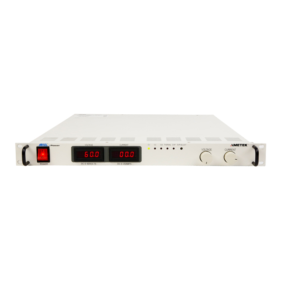
SECTION 3 OPERATION INTRODUCTION The SPS-A series provides simplicity and ease of analog front panel potentiometer controls. LED screens display bright, easy-to-read voltage and current output measurements. This section provides detailed information on the operation of the SPS-A series. WARNING! The power-up factory default state is output enabled. - Page 44 Operation AMREL SPS-A Series Figure 3-1 descriptions: ON/OFF Switch Two–position switch enables or disables the power supply. WARNING: OFF does not remove voltage from the input terminal blocks. Remove external power before servicing the unit. Voltage Display 3½ digit green LED screen displays the supply’s DC output voltage.
-
Page 45: Figure 3-2. Sg Rear Panel With Gpib Option (40V-800V)
AMREL SPS-A Series Operation Figure 3-2. SG Rear Panel with GPIB Option (40V-800V) Figure 3-3. SG Rear Panel with GPIB Option (10V-300V) M550129-01 Rev A... - Page 46 Operation AMREL SPS-A Series Figure 3-2 and Figure 3-3 descriptions: RS232 Connector Connector for remote control SENSE Connector J3 Input connector for load voltage sensing to correct for line drops in the load cables (see Section 3.6). 2a HV SENSE Connector J3 Input connector for load voltage sensing, 800V models only.
-
Page 47: Figure 3-4. Sg Rear Panel With Ethernet Option (40V-800V)
AMREL SPS-A Series Operation 11 4a Figure 3-4. SG Rear Panel with Ethernet Option (40V-800V) Figure 3-5. SG Rear Panel with Ethernet Option (10V-30V) M550129-01 Rev A... - Page 48 Operation AMREL SPS-A Series Figure 3-4 and Figure 3-5 descriptions: ETHERNET Connector Connector for remote control via Ethernet. RS232 Connector Connector for remote control ANALOG CONTROL J1 I/O connector for input programming and analog output monitoring signals as well as status indication and remote shutdown signals.
-
Page 49: Figure 3-6. Sps-A 6U Rear Panel With Gpib/Rs232 Option Connectors
AMREL SPS-A Series Operation Figure 3-6. SPS-A 6U Rear Panel with GPIB/RS232 Option Connectors Figure 3-6 descriptions: ANALOG CONTROL J1 I/O connector for input programming and analog output monitoring signals as well as status indication and remote shutdown signals. See Table 3–1 for individual pin descriptions. SENSE Connector J3 input connector for load voltage sensing to correct for line drops in the load cables (see Section 3.6). -
Page 50: Shaft Lock (Option)
Operation AMREL SPS-A Series 3.2.2 SHAFT LOCK (OPTION) This option replaces the standard control knobs with a two-piece shaft lock. These are installed over the voltage and current adjustment potentiometer shafts to prevent rotating under conditions of shock, vibration, or accidental contact. For adjustment, the following steps apply: •... -
Page 51: Local Operation
AMREL SPS-A Series Operation LOCAL OPERATION The SPS-A Series power supply is shipped from the factory configured for local voltage/current control and local voltage sensing. The ANALOG CONTROL connector is supplied with a mating connector with remote output ON/OFF jumpered for ON (terminal 5 shorted to terminal 6). WARNING! The power-up factory default state is output enabled. -
Page 52: Initial Setup
Operation AMREL SPS-A Series 3.3.2 INITIAL SETUP 1. Before connecting the unit to an AC outlet, ensure that the front panel ON/OFF power switch is in the OFF position. 2. Ensure that the Voltage and Current control knobs are fully counterclockwise. 3. -
Page 53: Current Mode Operation
AMREL SPS-A Series Operation 3.3.4 CURRENT MODE OPERATION When the supply is in the Current Mode, the output current of the supply is controlled by the Current knob on the front panel or by the remote current input (see Section 3.4). The Voltage control knob (or remote voltage input) operates as a voltage limit. -
Page 54: Overvoltage Protection
Operation AMREL SPS-A Series 3.3.5 OVERVOLTAGE PROTECTION The Overvoltage Protection (OVP) function allows the supply to shutdown the output when it exceeds a preset voltage. This may be used to protect sensitive circuits or loads from damage caused by an excessive voltage on the output of the supply. -
Page 55: Analog Control Connector (J1)
AMREL SPS-A Series Operation 3.3.6 ANALOG CONTROL CONNECTOR (J1) The ANALOG CONTROL connector on the rear panel allows the unit to be configured for different operating configurations: local and remote current programming, local and remote voltage programming, current and voltage output monitoring, output enable/disable, etc. The setup and operating requirements of each configuration are provided in Sections 3.4 through 3.9. - Page 56 Operation AMREL SPS-A Series Schematic Electrical Functional Description Symbol Chars. Isolated remote output on/off. Externally supplied AC/DC voltage source for on/off control. A positive (+) 12 to 240 VAC or 6 to 120 VDC voltage will enable the output, i.e., ISO ON/OFF Zin ~ 6 kΩ...
- Page 57 AMREL SPS-A Series Operation Schematic Electrical Functional Description Symbol Chars. 0-5 VDC (0-100%) front panel current potentiometer set Zout ~ point monitor output. Minimum load resistance ISET 100Ω 10kΩ. Circuit return Pin 6 (COM). Not Used Isolated TTL/CMOS on/off control. A high state TTL/CMOS voltage enables the output, i.e., turns on the Zin ~ 2.2kΩ...
-
Page 58: Table 3-1. Analog Control Connector (J1), Designations And Functions
Operation AMREL SPS-A Series Schematic Electrical Functional Description Symbol Chars. 1 milliamp current source for remote current programming ~ 10.8V using resistance. 0-5k ohm resistor referenced to Circuit IP RES compliance return Pin 23 or Pin 25 (IP RTN) will program the output current from 0-100%. -
Page 59: Remote Current Programming
AMREL SPS-A Series Operation REMOTE CURRENT PROGRAMMING Remote current programming is used for applications that require the output current be programmed (controlled) from a remote source. An external resistance or external voltage source may be used as a programming device. When using remote current programming, a shielded, twisted-pair, hookup wire is recommended to prevent noise interference with programming signals. -
Page 60: Remote Current Programming Using A 0-5 Or 0-10 Vdc Voltage Source
Operation AMREL SPS-A Series 3.4.2 REMOTE CURRENT PROGRAMMING USING A 0-5 OR 0-10 VDC VOLTAGE SOURCE A DC voltage source for remote current programming is connected between J1-10 (IP 5V) or J1-16 (IP 10V) and the return terminal J1-23 (IP RTN). Note: The return terminal J1-23 (IP RTN) must be referenced directly to or within ±3V of the power supply common, J1-24. -
Page 61: Remote Voltage Programming
AMREL SPS-A Series Operation REMOTE VOLTAGE PROGRAMMING Remote voltage programming configuration is used for applications that require the output voltage be programmed (controlled) from a remote source. An external resistance or external voltage source may be used as a programming device. When using remote voltage programming, a shielded, twisted-pair, hookup wire is recommended to prevent noise interference with programming signals. -
Page 62: External Voltage Programming Using A 0-5 Or 0-10 Vdc Voltage Source
Operation AMREL SPS-A Series 3.5.2 EXTERNAL VOLTAGE PROGRAMMING USING A 0-5 OR 0-10 VDC VOLTAGE SOURCE A DC voltage source for remote voltage programming is connected between J1-9 (VP 5V) or J1-15 (VP 10V) and the return terminal J1-20 (VP RTN). Note: The return terminal (VP RTN) must be referenced directly to or within ±3V of the power supply common, J1-24. -
Page 63: Remote Sensing
AMREL SPS-A Series Operation REMOTE SENSING Remote voltage sensing is recommended at all times, whether you connect sensing leads to the load or directly to the output terminals. Remote sensing at the load provides the best load regulation. In applications where the load is located some distance from the power supply, or the voltage drop of the power output leads significantly interferes with load regulation, remote voltage sensing should definitely be used. -
Page 64: Figure 3-14. Remote Sensing Operation At The Load
Operation AMREL SPS-A Series CAUTION! If the power supply is operated with load power lines disconnected and sensing line connected, internal power supply damage may occur. (Output current then flows through sensing terminals.) To use remote voltage sensing, connect the power supply as described below. -
Page 65: Remote Output On/Off Control
AMREL SPS-A Series Operation REMOTE OUTPUT ON/OFF CONTROL Remote output on/off control may be accomplished by contact closure or by an isolated external AC/DC or TTL/CMOS voltage source. 3.7.1 REMOTE OUTPUT ON/OFF BY CONTACT CLOSURE Output is on when contacts (J1-5 and J1-6) are closed. See Figure 3-15 for connection requirements. -
Page 66: Remote Overvoltage Setpoint
Operation AMREL SPS-A Series 14 ISO TTL/CMOS ISO RTN 2 Figure 3-17. Remote Output ON/OFF Using Isolated TTL/CMOS Voltage Supply REMOTE OVERVOLTAGE SETPOINT CAUTION! Do not program the remote overvoltage set point greater than 10% (5.5V) above the power supply rated voltage (except as noted) as internal power supply damage may occur. -
Page 67: Remote Shutdown (S/D)
AMREL SPS-A Series Operation REMOTE SHUTDOWN (S/D) A remote +12 VDC voltage can be connected externally between terminals J1-18 (S/D Fault) and J1-24 (COM) to disable, i.e., shut down the output of the power supply (Figure 3-19). Disabling or opening the +12 VDC signal will allow the unit to revert to normal operation. -
Page 68: Parallel And Series Operation
Operation AMREL SPS-A Series PARALLEL AND SERIES OPERATION 3.10 The following modes of operation are used for applications requiring more current or voltage than is available from a single power supply. To meet the requirements for greater output voltage or current, two supplies may be connected in series or up to five connected in parallel. -
Page 69: Series Operation
AMREL SPS-A Series Operation Figure 3-20. Parallel and Remote/Local Sense Connections Note: The OVP circuit remains active for all units in parallel operation. If the units are set to different OVP levels, the paralleled system will trip according to the lowest setting. - Page 70 Operation AMREL SPS-A Series higher output voltage range is required, contact the Sales Department or Customer Service for availability. • The maximum allowable current for a series string of power supplies is the rated output current of a single supply in the string. •...
- Page 71 AMREL SPS-A Series Operation This page intentionally left blank. M550129-01 Rev A 3-29...
-
Page 73: Maintenance
SECTION 4 MAINTENANCE INTRODUCTION This chapter contains preventive maintenance information for the SPS-A Series power supplies. WARNING! All maintenance that requires removal of the cover of the unit should only be done by properly trained and qualified personnel. Hazardous voltages exist inside the unit. -
Page 74: Table 4-1. Recommended Annual Inspection
Maintenance AMREL SPS-A Series An annual inspection of the SPS-A Series unit is recommended. Table 4– 1 lists the visual inspection checks to be performed, and the corrective action to be taken. Table 4–1. Recommended Annual Inspection Item Inspect For Corrective Action External connector Looseness, bent or corroded... -
Page 75: Fuses
AMREL SPS-A Series Maintenance FUSES There are no user replaceable components in the power supply. WARNING! Only properly trained and qualified personnel should remove the cover from the power supply. Service, fuse verification, and connection of wiring to the chassis must be accomplished at least five minutes after power has been removed via external means;... - Page 76 Maintenance AMREL SPS-A Series This page intentionally left blank. M550129-01 Rev A...
- Page 77 INDEX Circuit Breaker Requirements, 1-4, 1-5 Noise, 1-4, 1-5 Controls and Indicators, 3-1 Analog Control (J1), 3-14 Current Mode Operation Operation, 3-12 Current Mode, 3-12 Local, 3-10 Master/Slave, 3-27 Fuses, 4-3 Parallel, 3-27 Remote Current Programming, 3-18 Remote Output On/Off Control, 3-24 Remote Overvoltage Setpoint, 3-25 Inductive Loads, 1-9 Remote Sensing, 3-22...
- Page 78 Index AMREL SPS-A Series Ripple, 1-4 Voltage, 1-4 Series Operation, 3-28 Setup, 3-11 Shaft Lock, 3-9 Ventilation, 1-2 Specifications, 1-2 Voltage Mode Current, 1-4 Operation, 3-11 Electrical Characteristics, 1-2 Environmental Characteristics, 1-2 Noise, 1-4 Physical Characteristics, 1-5 Wire Size, 1-6 Index 2 M550129-01 Rev A...
Need help?
Do you have a question about the SPS A Series and is the answer not in the manual?
Questions and answers