
Related Manuals for Ametek Sorensen DHP Series


Summary of Contents for Ametek Sorensen DHP Series
- Page 1 DHP Series DC Power Supplies Operation Manual M550004-01 Rev K www.programmablepower.com...
-
Page 5: Contact Information
About AMETEK AMETEK Programmable Power, Inc., a Division of AMETEK, Inc., is a global leader in the design and manufacture of precision, programmable power supplies for R&D, test and measurement, process control, power bus simulation and power conditioning applications across diverse industrial segments. - Page 6 This page intentionally left blank.
-
Page 7: Important Safety Instructions
Important Safety Instructions Before applying power to the system, verify that your product is configured properly for your particular application. Hazardous voltages may be present when covers are removed. Qualified personnel must use extreme caution when servicing this equipment. Circuit boards, test points, and output voltages also may be floating above WARNING (below) chassis ground. - Page 8 This page intentionally left blank.
- Page 9 Product Family: DHP Series DC Power Supplies Warranty Period: Five Years WARRANTY TERMS AMETEK Programmable Power, Inc. (“AMETEK”), provides this written warranty covering the Product stated above, and if the Buyer discovers and notifies AMETEK in writing of any defect in material or workmanship within the applicable warranty period stated above, then AMETEK may, at its option: repair or replace the Product;...
- Page 10 This page intentionally left blank. WA-2...
-
Page 11: Table Of Contents
TABLE OF CONTENTS Chapter 1 DESCRIPTION OF EQUIPMENT ................. 1-1 PURPOSE AND CAPABILITIES ________________________________________ 1-1 TECHNICAL CHARACTERISTICS ______________________________________ 1-1 Chapter 2 INSTALLATION......................2-1 INSPECTION_______________________________________________________ 2-1 INPUT/OUTPUT CONNECTORS _______________________________________ 2-1 LOCATION AND MOUNTING __________________________________________ 2-1 WIRE SIZING ______________________________________________________ 2-4 OUTLINE DRAWINGS _______________________________________________ 2-4 Chapter 3 OPERATING INSTRUCTIONS................ - Page 12 LIST OF FIGURES Figure 2-1 Outline Drawing, 2kW to 3kW (Output Voltage <=60 V) ............2-5 Figure 2-2 Outline Drawing, 2kW to 3kW (Output Voltage >=80 V) ............2-6 Figure 2-3 Outline Drawing, 3.3kW to 15kW (Output Voltage <=60 V) ............. 2-7 Figure 2-4 Outline Drawing, 3.3kW to 15kW (Output Voltage >=80 V) .............
-
Page 13: Chapter 1 Description Of Equipment
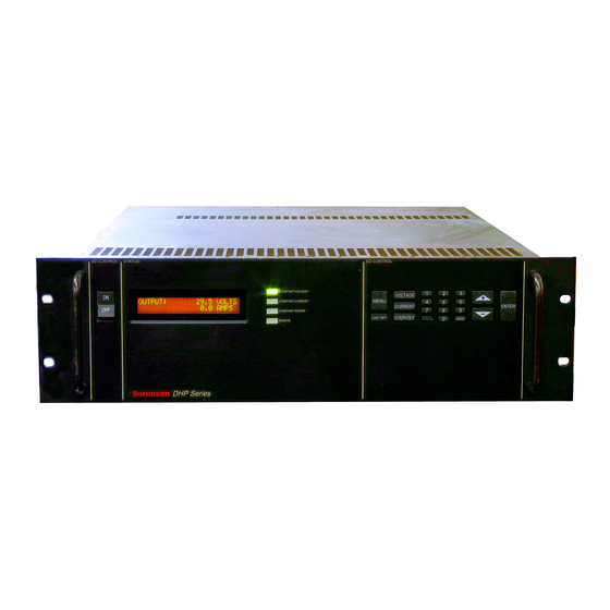
DESCRIPTION OF EQUIPMENT 1.1 PURPOSE AND CAPABILITIES The Sorensen DHP Series power supplies are general purpose power supplies designed specifically for laboratory test and systems applications requiring variable DC sources with good ripple and regulation characteristics. The DHP power supplies include three separate series: the 2U High, the 3U High and the 6U High. -
Page 14: Table 1-1 2 Kw To 3 Kw Series Technical Characteristics
Table 1-1 2 kW to 3 kW Series Technical Characteristics PARAMETERS SPECIFICATIONS PHYSICAL CHARACTERISTICS Width 19.00 in. Depth 18.00 in (output connections not included) Height 3.50 in. Weight 45 lbs. max. ELECTRICAL CHARACTERISTICS Input Power (Standard) Voltage 208-230 VAC (tested to 190-253 VAC) Frequency 47 to 63 Hz Phases... - Page 15 Table 1-1 High Series Technical Characteristics – Continued 2 kW to 3 kW PARAMETERS SPECIFICATIONS REMOTE PROGRAMMING Resistive: Constant Voltage (0-100%) 0 - 5k ohms Constant Current (0-100%) 0 - 5k ohms Voltage: Constant Voltage (0-100%) 0 - 5/10 VDC Constant Current (0-100%) 0 - 5/10 VDC Remote Sensing...
-
Page 16: Table 1-2 5Kw To 15Kw And 16Kw To 30Kw Series Technical Characteristics
Table 1-2 5kW to 15kW and 16kW to 30kW Series Technical Characteristics PARAMETERS SPECIFICATIONS ≤60V to 10kW ≤60V to 20kW PHYSICAL CHARACTERISTICS ≥80V to 15kW ≥80V to 30kW 600V to 10kW 600V to 20kW Width 19.00 in. 19.00 in. Depth 22.00 in. - Page 17 Table 1-2 Series Technical Characteristics - Continued 5kW to 15kW and 16kW to 30kW PARAMETERS SPECIFICATIONS REMOTE PROGRAMMING Resistive 0 - 5k ohms Constant Voltage (0-100%) 0 - 5k ohms Constant Current (0-100%) Voltage 0 - 5 VDC or 0 -10 VDC Constant Voltage (0-100%) 0 - 5 VDC or 0 -10 VDC Constant Current (0-100%)
-
Page 18: Table 1-3 Available Voltages And Currents
Table 1-3 Available Voltages and Currents 2U HEIGHT 3U HEIGHT 6U HEIGHT V Out 6.6KW 10KW 15KW 13.3KW 16.6KW 20KW 25KW 30KW 1000 1500 2000 2500 3000 1200 1600 2000 2400 1000 1300 1650 2000 12.5 1060 1325 1600 1100 1320 1000 Output Ripple - Typical... -
Page 19: Chapter 2 Installation
Chapter 2 INSTALLATION 2.1 INSPECTION Inspect the shipping carton for possible damage before unpacking the unit. Carefully unpack the equipment. Save all packing materials until inspection is complete. Verify that all items listed on the packing slips have been received. Visually inspect all exterior surfaces for broken knobs, connectors, or meters. -
Page 20: Table 2-1 2Kw To 3Kw High Series Input/Output Connectors
Follow the instructions in paragraph 3-2 for setup and operation of the equipment. Table 2-1 2kW to 3kW High Series Input/Output Connectors CONNECTOR FUNCTION CONNECTS TO FL1 - AC Prime Power Input 190-253 VAC (Std) FL1 – AC (Std) 47-63 Hz FL1-AC (with opt. -
Page 21: Table 2-3 Output Connection Descriptions
Table 2-3 Output Connection Descriptions* SUPPLY TYPE CONNECTION DESCRIPTION 2kW to 3kW <=60V Bus Bar with hole for 3/8” bolt 6.6kW to 10kW <=60V Bus Bar with two holes for 3/8” bolts 13.3kW to 20kW <=60V Bus Bar with three holes for 3/8” bolts 2kW to 3kW >=80V Terminal Block with 10-32 screws... -
Page 22: Wire Sizing
2.4 WIRE SIZING Care must be taken to properly size all conductors for the input and output of the power supply. Table 2-5 below gives minimum recommended wire size for the input. This table is derived from the National Electrical Code and is for reference only. Local laws and conditions may have different requirements. -
Page 23: Figure 2-1 Outline Drawing, 2Kw To 3Kw (Output Voltage <=60 V)
AC CONTROL STATUS DC CONTROL CONSTANT VOLTAGE MENU CONSTANT CURRENT ENTER CONSTANT POWER LAST SET REMOTE Figure 2-1 Outline Drawing, 2kW to 3kW (Output Voltage <=60 V) M550004-01... -
Page 24: Figure 2-2 Outline Drawing, 2Kw To 3Kw (Output Voltage >=80 V)
AC CONTROL STATUS DC CONTROL CONSTANT VOLTAGE MENU CONSTANT CURRENT ENTER CONSTANT POWER LAST SET REMOTE Figure 2-2 Outline Drawing, 2kW to 3kW (Output Voltage >=80 V) M550004-01... -
Page 25: Figure 2-3 Outline Drawing, 3.3Kw To 15Kw (Output Voltage <=60 V)
AC CONTROL STATUS DC CONTROL CONSTANT VOLTAGE CONSTANT CURRENT MENU ENTER CONSTANT POWER LAST SET REMOTE Figure 2-3 Outline Drawing, 3.3kW to 15kW (Output Voltage <=60 V) M550004-01... -
Page 26: Figure 2-4 Outline Drawing, 3.3Kw To 15Kw (Output Voltage >=80 V)
AC CONTROL STATUS DC CONTROL CONSTANT VOLTAGE CONSTANT CURRENT MENU ENTER CONSTANT POWER LAST SET REMOTE Figure 2-4 Outline Drawing, 3.3kW to 15kW (Output Voltage >=80 V) M550004-01... -
Page 27: Figure 2-5 Outline Drawing, 13.3Kw & 16Kw To 30Kw (Output Voltage <=60 V)
AC CONTROL STATUS DC CONTROL CONTSTANT VOLTAGE CONTSTANT CURRENT MENU ENTER CONTSTANT POWER LAST SET REMOTE Figure 2-5 Outline Drawing, 13.3kW & 16kW to 30kW (Output Voltage <=60 V) M550004-01... -
Page 28: Figure 2-6 Outline Drawing, 13.3Kw & 16Kw To 30Kw (Output Voltage >=80 V)
AC CONTROL STATUS DC CONTROL CONTSTANT VOLTAGE MENU CONTSTANT CURRENT ENTER CONTSTANT POWER LAST SET REMOTE Figure 2-6 Outline Drawing, 13.3kW & 16kW to 30kW (Output Voltage >=80 V) 2-10 M550004-01... -
Page 29: Chapter 3 Operating Instructions
Chapter 3 OPERATING INSTRUCTIONS 3.1 CONTROLS AND INDICATORS Front panel controls and indicators for the DHP Series are identified in Figure 3-1. Although different models may have different heights, the controls remain the same across the entire series. Table 3-1 provides a description of all operator controls and indicators. -
Page 30: Basic Operation
3.2 BASIC OPERATION The following section describes the basic operation of the power supply including the use of most keyboard functions and the related displays. ACTION / PROCEDURE DISPLAY Turn power switch to ON INITIALIZING The Model Number is identified and initialization begins. Initializing consists of internal diagnostics and self-calibration of control boards. - Page 31 keypad or, using the keys, scroll to desired limit. Press ENTER to set limit. SET OVERVOLTAGE Press overvoltage button, then enter limit from keypad or, using the keys, scroll to desired limit. Press ENTER to set limit. MENU BUTTON Use the menu button to access advanced functions of the power supply.
- Page 32 Cycle the MENU button to Save To Memory and select a memory location by entering it from the key pad or by scrolling to it using the keys. Once selected, press ENTER and all current settings will be saved. CONTROL SOURCE The control source for the power supply is the location from which the output of the power supply can be controlled.
- Page 33 SCPI CONTROL OPTIONS (Optional) This will only display when a SCPI option is installed. Details on use of this option are included in the SCPI Option User’s Manual. INT DATA The internal data menu provides information about the internal operation of the power supply.
-
Page 34: Table 3-2 J1 Designations And Functions
Table 3-2 J1 Designations and Functions SCHEMATIC FUNCTIONAL DESIGNATOR SYMBOL DESCRIPTION ISO ON/OFF Isolated remote on/off. Externally supplied AC/DC voltage source for output on/off control. A positive (+) voltage will turn on the output of the supply. This input control is optically isolated from the power supply circuit up to 500 VDC. - Page 35 Table 3-2 J1 Designations and functions - Continued SCHEMATIC FUNCTIONAL DESIGNATOR SYMBOL DESCRIPTION V PROG Remote voltage programming using a 0-5 or 0-10 VDC source (same signal as pin 9). I PROG Remote current programming using a 0-5 or 0-10 VDC source (same signal as pin 10).
-
Page 36: Local Operation
The power supply may be configured via connector J1 on the rear panel for different operating configurations: local and remote current programming, local and remote voltage programming, normal parallel, auto-parallel, normal series, auto-series, and auto-tracking. The use and operating requirements of each configuration are provided in the following paragraphs. -
Page 37: Remote Voltage Programming
External Current Programming Using a 0-5 VDC or 0-10 VDC Voltage Source. A DC voltage source for remote current programming is connected between J1-10 or J1-16 (IPROG) and the return terminal J1-23 (IP RTN). Note that the return terminal J1-23 (IP RTN) must be referenced directly to or within ±3V of the power supply common, J1-24. -
Page 38: Remote Output On/Off Control
regulated at the load versus the power supply output terminals. To connect the power supply for remote voltage sensing (see Figure 3-7 for connection requirements), perform the following procedure. CAUTION If the power supply is operated with load power lines disconnected and sensing line connected, internal power supply damage may occur. -
Page 39: Figure 3-3 Remote Current Programming Using Resistance
16 I PROG COM 6 22 IP RES 23 IP RTN 0-5 Kohms PROGRAM Figure 3-3 Remote Current Programming Using Resistance COM 6 IPROG 10 0-5 VDC 23 IP RTN 0-10 VDC VOLTAGE SOURCE Figure 3-4 Remote Current Programming Using 0-5 or 0-10 VDC Source M550004-01 3-11... -
Page 40: Figure 3-5 Remote Voltage Programming Using Resistance
15 VPROG 20 VP RTN COM 6 21 VP RES 0-5 Kohms PROGRAM Figure 3-5 Remote Voltage Programming Using Resistance COM 6 20 VP RTN VPROG 9 0-5 VDC 0-10 VDC VOLTAGE SOURCE Figure 3-6 Remote Voltage Programming Using 0-5 or 0-10 VDC Source 3-12 M550004-01... -
Page 41: Figure 3-7A Remote Sensing Operation At The Load
LOAD − SUPPLY OUTPUT TERMINALS Figure 3-7a Remote Sensing Operation at the Load ≥ Remote Sensing Operation at the Load 80V Out SUPPLY OUTPUT TERMINALS − LOAD SENSE - 12 SENSE + 13 Figure 3-8b ≤ Remote Sensing Operation at the Load 60V Out M550004-01 3-13... -
Page 42: Figure 3-9 Remote On/Off Control By Contact Closure
ON/OFF 5 Figure 3-9 Remote On/Off Control by Contact Closure ISO ON/OFF 1 ISO RTN 2 AC OR DC SOURCE Figure 3-10 Remote On/Off Using Isolated AC or DC Voltage Source 3-14 M550004-01... -
Page 43: Figure 3-11 Remote On/Off Using Isolated Ttl/Cmos Voltage Supply
14 ISO TTL/CMOS ISO RTN 2 Figure 3-11 Remote On/Off Using Isolated TTL/CMOS Voltage Supply REM OV SET 3 0-5.5 VDC COM 6 VOLTAGE SOURCE Figure 3-12 Remote Overvoltage Set Using DC Voltage Source M550004-01 3-15... - Page 44 This page intentionally left blank. 3-16 M550004-01...
-
Page 45: Chapter 4 Auto-Step Programming
Chapter 4 AUTO-STEP PROGRAMMING 4.1 INTRODUCTION The DHP series power supplies allow the user to enter a sequence of up to nine steps into memory for later execution. These steps include settings for voltage, current, OVP, and time for each step. A simple programming sequence is used. This chapter describes the use of the auto-step programming feature of the power supply. -
Page 46: Figure 4-2 Auto-Step Programming Menu System
Figure 4-2 Auto-step Programming Menu System M550004-01... -
Page 47: Figure 4-3 Programming Start Screen
After entering the programming mode the Programming Start Screen is displayed. The components of this screen are shown in Figure 4-3. This screen allows the user to review the settings for each step that has been programmed and to choose a step to change, if desired. -
Page 48: Running A Program
At this point, if ‘N’ (Proceed to Next step) was chosen the (up) key may be used to select the next step for programming. If R (Repeat steps) or S (Stop) was chosen, then the LAST SET key may be pushed to exit the Auto-step Programming Mode. After pressing the LAST SET key the supply will return to normal operating mode. -
Page 49: Chapter 5 Calibration
Chapter 5 CALIBRATION 5.1 INTRODUCTION This power supply has been design to be extremely easy to calibrate. A minimum of tools and instrumentation are required, and all adjustments are made from the front panel. 5.2 REQUIRED EQUIPMENT Four items are needed to calibrate the power supply; these are: A 5 ½... -
Page 50: Figure 5-2 Calibration Abort Screen
After pressing ENTER a warning screen will display as shown in Figure 5-2. This display gives the user a chance to abort the calibration sequence without changing any internal calibration constants or to continue with the calibration. Figure 5-2 Calibration Abort Screen To abort the calibration sequence press the CANCEL key. -
Page 51: Figure 5-5 Hot Shunt Warning Screen
In this figure the number 230 is for example only and will vary with each supply. The “OK” means the value being read internally is within an acceptable range and the calibration may proceed. At this time read the output current using the volt meter and shunt, and using the numeric keypad enter the correct current to five places. -
Page 52: Figure 5-7 Prepare Load Screen
Figure 5-7 Prepare Load Screen When the load is properly connected press ENTER. At this time the supply will output a small voltage and request that you tell it exactly what that voltage is. The display will be as shown in Figure 5-8. Figure 5-8 Voltage Calibration 1 In this figure the number 230 is for example only and will vary with each supply. -
Page 53: Figure 5-10 Voltage Calibration 2
Proceed with the calibration by pressing ENTER again. At this time the output voltage will rise to about 90% of the rating of the supply, and the screen displayed in Figure 5-10 will be displayed. Figure 5-10 Voltage Calibration 2 In this figure the number 3300 is for example only and will vary with each supply. - Page 54 This page intentionally left blank. M550004-01...
-
Page 55: Chapter 6 Maintenance
Chapter 6 MAINTENANCE 6.1 INTRODUCTION This chapter contains preventive maintenance information for the DHP Series. WARNING All maintenance that requires removal of the cover of the unit should only be done by properly trained and qualified personnel. Hazardous voltages exist inside the unit. Disconnect the supply from the input power before performing... -
Page 56: Table 6-2 Inspection And Corrective Action
Table 6-2 Inspection and Corrective Action ITEM INSPECT FOR CORRECTIVE ACTION Connector plugs and Loose, bent or corroded Clean contacts with solvent jacks contacts, damage or improper moistened cloth, soft bristle brush, seating in mating connector small vacuum, or low compressed air.