
Related Manuals for Ametek Sorensen SGI Series


Summary of Contents for Ametek Sorensen SGI Series
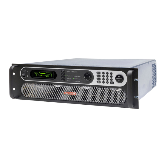
- Page 1 SGI Series DC Power Supplies Operation Manual M550221-01 Rev U www.programmablepower.com...
-
Page 3: Contact Information
About AMETEK AMETEK Programmable Power, Inc., part of the Programmable Power Division of AMETEK, Inc., is the new global leader in the design and manufacture of precision, programmable power supplies for R&D, test and measurement, process control, power bus simulation and power conditioning applications across diverse industrial segments. - Page 4 AMETEK will, at its expense, deliver the repaired or replaced Product or parts to the Buyer. Any warranty of AMETEK will not apply if the Buyer is in default under the Purchase Order Agreement or where the Product or any part thereof: ...
-
Page 5: Important Safety Instructions
Use safety glasses during open cover checks to avoid personal injury by any sudden component failure. Neither AMETEK Programmable Power Inc., San Diego, California, USA, nor any of the subsidiary sales organizations can accept any responsibility for personnel, material or inconsequential injury, loss or damage that results from improper use of the equipment and accessories. -
Page 6: Safety Symbols
SAFETY SYMBOLS WARNING: Electrical Shock Hazard HAZARD: Strong oxidizer GENERAL WARNING/CAUTION: Read the accompanying message for specific information. BURN HAZARD: Hot Surface Warning. Allow to cool before servicing. DO NOT TOUCH: Touching some parts of the instrument without protection or proper tools could result in damage to the part(s) and/or the instrument. -
Page 7: Fcc Notice
FCC NOTICE This equipment has been tested and found to comply with the limits for a Class A digital device, pursuant to part 15 of the FCC Rules. These limits are designed to provide reasonable protection against harmful interference when the equipment is operated in a commercial environment. -
Page 8: About This Manual
ABOUT THIS MANUAL This manual has been written expressly for the Sorensen SGI Series of power supplies that have been designed and certified to meet the Low Voltage and Electromagnetic Compatibility Directive Requirements of the European Community. These models have been designed and tested to meet the Electromagnetic Compatibility directive (European Council directive 2004/108/EC;... -
Page 9: Table Of Contents
CONTENTS SECTION 1 OVERVIEW .......... 1-1 General Description ..................1-1 Specifications ....................1-3 1.2.1 Environmental Characteristics ................ 1-3 1.2.2 Electrical Characteristics ................1-3 1.2.3 SGI Series Voltage and Current Specifications ..........1-7 1.2.4 Physical Characteristics ................. 1-8 SECTION 2 INSTALLATION ........2-1 Inspection ..................... - Page 10 Contents Sorensen SGI Series 3.2.2 Default Programming Menu ................3-9 3.2.3 Constant-Voltage Mode Operation ...............3-10 3.2.4 Constant-Current Mode Operation ...............3-11 3.2.5 Overvoltage Protection .................3-12 Initial Start-Up Displays ................3-13 Display Elements ..................3-14 Navigation ....................3-15 Editing ......................3-16 3.6.1 Aborting an Edit ....................3-17...
- Page 11 Sorensen SGI Series Contents 3.10.2 Remote Current Programming by Voltage Source ........3-44 3.11 Remote Voltage Programming ..............3-45 3.11.1 Remote Voltage Programming by Resistance ..........3-45 3.11.2 Remote Voltage Programming by Voltage Source ........3-46 3.12 Remote Overvoltage Programming ............3-47 3.13 Remote Output On/Off Control ..............3-48 3.13.1...
- Page 12 Contents Sorensen SGI Series LIST OF TABLES Table 2–1. Maximum AC Current Ratings, PFC Models ..........2-5 Table 2–2. Maximum AC Current Ratings, Non-PFC Models ........2-5 Table 2–3. Input/Output Connectors ................2-5 Table 2–4. Input Terminal Connections ............... 2-6 Table 2–5.
- Page 13 Sorensen SGI Series Contents LIST OF FIGURES Figure 1-1. Model Number Decoding ................1-2 Figure 2-1. Diode Connection ................... 2-10 Figure 2-2. Installation Drawing, 3U Models 10V-30V ..........2-12 Figure 2-3. Installation Drawing, 3U Models 40V-600V ..........2-13 Figure 2-4. Installation Drawing, 3U Models 800V and 1000V ......... 2-14 Figure 2-5.
- Page 14 Contents Sorensen SGI Series Figure 3-24. Remote Sense Connection at the Load, 10V-800V Models ....3-51 Figure 3-25. Remote Sense Connection at the Load, 1000V Model ......3-52 Figure 3-26. Parallel Connection and Remote Sense ..........3-55 Figure 4-1. Potentiometer Locations ................4-8...
-
Page 15: Section 1 Overview
SECTION 1 OVERVIEW General Description The Sorensen SGI Series are general purpose power supplies designed specifically for laboratory test and systems applications requiring programmable DC sources with good performance characteristics, such as accuracy, regulation, and ripple/noise. These power supplies are constant- current/constant-voltage supplies with an automatic crossover feature. -
Page 16: Figure 1-1. Model Number Decoding
Overview Sorensen SGI Series SG I 100 X 100 C - 1A AA AJ Control Designation Modifications A = Analog I = Intelligent Voltage Process Options 4-15 kW = "X" Remote Control Options 20-30 kW = "/" Input Voltage Options Current For units up to 999 V/999 A, voltage and current are represented in numeric format, e.g., “100”... -
Page 17: Specifications
Sorensen SGI Series Overview Specifications The following subsections provide environmental, electrical, and physical characteristics for the SGI Series power supplies. Note: Specifications are subject to change without notice. Note: The SGI Series power supplies are intended for indoor use only. Refer to Section 2.3 for use/location requirements. - Page 18 Overview Sorensen SGI Series Parameter Specification Power Factor (at full rated load; 50/60Hz); contact factory for power factor of specific models PFC models: 10V-30V, 50V, 0.90, typical, for all AC input ratings; with passive power factor 1000V, and models with optional correction (PFC) modification, “PF”...
- Page 19 Sorensen SGI Series Overview Parameter Specification 10 ms, maximum, from 90-10% of programming change from Output Voltage Fall Time rated output voltage to zero for 10V-30V models; (with rated load, resistive) contact factory for values of specific models 50 ms, maximum, from 90-10% of programming change from rated output voltage to zero for 10V-30V models;...
- Page 20 Overview Sorensen SGI Series Parameter Specification ±0.8%, maximum, of rated output current for 0-5 VDC range, and ±1.0%, maximum, for 0-10 VDC range for 40V-1000V models Overvoltage Protection (OVP) ±1%, maximum, of rated output voltage Readback Monitor Accuracy ±0.5%, maximum, of rated output voltage...
-
Page 21: Sgi Series Voltage And Current Specifications
Sorensen SGI Series Overview 1.2.3 SGI Series Voltage and Current Specifications The following tables present the specifications for rated voltage and current, and ripple/noise for the 10V-1000V models. Ripple/ Ripple/ Rated Current, ADC Rated Noise** Noise* Voltage, RMS, PK–PK, 4 kW... -
Page 22: Physical Characteristics
Overview Sorensen SGI Series 1.2.4 Physical Characteristics 3U Models, 3U Models, 6U Models, Dimensions 10V-30V 40V-1000V 60V-600V Width 19.00 in (48.26 cm) 19.00 in (48.26 cm) 19.00 in (48.26 cm) From inner surface of front panel to maximum protrusion of protective covers at rear panel;... -
Page 23: Section 2 Installation
Series power supply, the ship kit may include additional parts and accessories. Minimum items included in the ship kit: AMETEK manuals CD-ROM (P/N M550008-01) containing the SGI Series DC Power Supplies Operation Manual (this manual, P/N M550221-01), and the SG manual for the digital interface options, IEEE 488.2/RS232 and Ethernet Programming Manual (P/N M550129-03). -
Page 24: Location And Mounting
Installation Sorensen SGI Series Hardware for input/output terminal power connections: 3U, 4-15 kW, 10V-30V models: 1/2-13UNC-2B x 1.25" long, 4 ea, with nut, washer, and lockwasher; 3U, 5-15 kW, 40V-600V models: 3/8-16UNC-2B x 1.0”, 2 ea, with nut, washer, and lockwasher;... -
Page 25: Rack Mounting
Rack Mount Slide Kit: 5–15 kW units: AMETEK P/N K550212-01 20–30 kW units: AMETEK P/N K550213-01 Secure the front panel of the unit to the rack using the screws provided. 2.3.2 6U Chassis Removal from Rack... -
Page 26: Input/Output Connections
Installation Sorensen SGI Series Input/Output Connections Refer to Table 2–1 for AC input current requirements and Section 1.2.3 for output current specifications. Table 2–3 provides information on the external input and output connections for the SGI Series models. Table 2–4 provides input connections descriptions and Table 2–5 provides output connection... -
Page 27: Table 2-1. Maximum Ac Current Ratings, Pfc Models
Sorensen SGI Series Installation Model Ratings Input Line Current, A (RMS)* AC Input Input Voltage Option Voltage, 5 kW 10 kW 15 kW 20 kW 25 kW 30 kW Model Code 208/230 380/400 40V-1000V 440/480 4 kW 8 kW 12 kW 5 kW... -
Page 28: Table 2-4. Input Terminal Connections
Installation Sorensen SGI Series Power Supply Type Connections Connection Description AC Input Feed-Through terminal block with 4 kW to 15 kW, 3U compression terminals AC Input 20 kW to 30 kW, 6U Bus Bar with holes for 1/4"–20 bolts Chassis Safety Ground... -
Page 29: Wire Selection
Sorensen SGI Series Installation Wire Selection Care must be taken to properly size all conductors for the input and output of the power supply. This section provides guidance in the selection of wire size. CAUTION! Cables with Class B or C stranding should be used. Fine-stranded (flexible) cables should not be used unless crimp-on lugs or ferrules are used that are approved for fine-stranded cables. - Page 30 Installation Sorensen SGI Series When determining the optimum cable specification for your power applications, the same engineering rules apply whether at the input or output of an electrical device. Thus, this guide applies equally to the AC input cable and DC output cable for this power supply and application loads.
-
Page 31: Table 2-9. Wire Resistance And Voltage Drop, 20°C
Sorensen SGI Series Installation Column 1 Column 2 Column 3 Column 4 Ohms/100 Ft Voltage Drop/100 Ft Size, AWG A(RMS) (One Way) (Column 2 x Column 3) 0.253 5.06 0.156 3.90 0.999 3.00 0.063 2.52 0.040 2.20 0.025 1.75 0.020 1.70... -
Page 32: Load Considerations
Installation Sorensen SGI Series LOAD CONSIDERATIONS This section provides guidelines for incorporating protective diode networks at the output of the power supply to prevent damage while driving inductive loads or loads having stored energy that could be circulated back to the power supply. -
Page 33: Outline Drawings
Sorensen SGI Series Installation Outline Drawings Figure 2-2 through Figure 2-5 show the outlines and overall dimensions for installation of the 3U and 6U models of the SGI Series power supplies. Figure 2-6 through Figure 2-14 show locations of rear panel connectors. -
Page 34: Figure 2-2. Installation Drawing, 3U Models 10V-30V
Installation Sorensen SGI Series Figure 2-2. Installation Drawing, 3U Models 10V-30V 2-12 M550221-01 Rev U... -
Page 35: Figure 2-3. Installation Drawing, 3U Models 40V-600V
Sorensen SGI Series Installation Figure 2-3. Installation Drawing, 3U Models 40V-600V M550221-01 Rev U 2-13... -
Page 36: Figure 2-4. Installation Drawing, 3U Models 800V And 1000V
Installation Sorensen SGI Series Figure 2-4. Installation Drawing, 3U Models 800V and 1000V 2-14 M550221-01 Rev U... -
Page 37: Figure 2-5. Installation Drawing, 6U Models 20Kw-30Kw
Sorensen SGI Series Installation Figure 2-5. Installation Drawing, 6U Models 20kW-30kW M550221-01 Rev U 2-15... -
Page 38: Figure 2-6. Rear Panel, Standard, 3U Models 10V-30V
Installation Sorensen SGI Series Figure 2-6. Rear Panel, Standard, 3U Models 10V-30V 2-16 M550221-01 Rev U... -
Page 39: Figure 2-7. Rear Panel, Gpib Option, 3U Models 10V-30V
Sorensen SGI Series Installation Figure 2-7. Rear Panel, GPIB Option, 3U Models 10V-30V M550221-01 Rev U 2-17... -
Page 40: Figure 2-8. Rear Panel, Ethernet Option, 3U Models 10V-30V
Installation Sorensen SGI Series Figure 2-8. Rear Panel, Ethernet Option, 3U Models 10V-30V 2-18 M550221-01 Rev U... -
Page 41: Figure 2-9. Rear Panel, Standard, 3U Models 40V-600V
Sorensen SGI Series Installation Figure 2-9. Rear Panel, Standard, 3U Models 40V-600V M550221-01 Rev U 2-19... -
Page 42: Figure 2-10. Rear Panel, Gpib Option, 3U Models 40V-600V
Installation Sorensen SGI Series Figure 2-10. Rear Panel, GPIB Option, 3U Models 40V-600V 2-20 M550221-01 Rev U... -
Page 43: Figure 2-11. Rear Panel, Ethernet Option, 3U Models 800V And 1000V
Sorensen SGI Series Installation Figure 2-11. Rear Panel, Ethernet Option, 3U Models 800V and 1000V M550221-01 Rev U 2-21... -
Page 44: Figure 2-12. Rear Panel, Standard, 6U Models 20Kw-30 Kw
Installation Sorensen SGI Series Figure 2-12. Rear Panel, Standard, 6U Models 20kW-30 kW 2-22 M550221-01 Rev U... -
Page 45: Figure 2-13. Rear Panel, Gpib Option, 6U Models 20Kw-30 Kw
Sorensen SGI Series Installation Figure 2-13. Rear Panel, GPIB Option, 6U Models 20kW-30 kW M550221-01 Rev U 2-23... -
Page 46: Figure 2-14. Rear Panel, Ethernet Option, 6U Models 20Kw-30 Kw
Installation Sorensen SGI Series Figure 2-14. Rear Panel, Ethernet Option, 6U Models 20kW-30 kW 2-24 M550221-01 Rev U... -
Page 47: Figure 2-15. Instructions For Assembly Of Ac And Dc Covers
Sorensen SGI Series Installation Figure 2-15. Instructions for Assembly of AC and DC Covers M550221-01 Rev U 2-25... - Page 48 Installation Sorensen SGI Series This page intentionally left blank. 2-26 M550221-01 Rev U...
-
Page 49: Section 3 Operation
SECTION 3 OPERATION Introduction The SGI Series adds powerful functionality and sequence programming to the SG family of DC power supplies. The graphical display, front panel keyboard, and context sensitive keys make setup of the sophisticated functions simple and easy. The following sections provide detailed information on the controls and indicators, programming conventions, and the front panel menu structure of the SGI Series. -
Page 50: Table 3-1. Front Panel Controls And Indicators
Operation Sorensen SGI Series WARNING! The power-up factory default state is output enabled, where the output will be energized at the settings of voltage and current. Item Reference Functional Description Two–position switch turns the power supply on and off. WARNING! -
Page 51: Figure 3-2. Rear Panel Interface, Standard, 3U Models 10V-30V
Sorensen SGI Series Operation Figure 3-2. Rear Panel Interface, Standard, 3U Models 10V-30V Figure 3-3. Rear Panel Interface, GPIB Option, 3U Models 10V-30V Figure 3-4. Rear Panel Interface, Ethernet Option, 3U Models 10V-30V M550221-01 Rev U... -
Page 52: Figure 3-5. Rear Panel Interface, Standard, 3U Models 40V-600V
Operation Sorensen SGI Series Figure 3-5. Rear Panel Interface, Standard, 3U Models 40V-600V Figure 3-6. Rear Panel Interface, GPIB Option, 3U Models 40V-600V Figure 3-7. Rear Panel Interface, Ethernet Option, 3U Models 800V and 1000V M550221-01 Rev U... -
Page 53: Figure 3-8. Rear Panel Interface, Standard, 6U Models 20Kw-30Kw
Sorensen SGI Series Operation Figure 3-8. Rear Panel Interface, Standard, 6U Models 20kW-30kW Figure 3-9. Rear Panel Interface, GPIB Option, 6U Models 20kW-30kW Figure 3-10. Rear Panel Interface, Ethernet Option, 6U Models 20kW-30kW M550221-01 Rev U... -
Page 54: Table 3-2. Rear Panel Connectors And Controls, Standard
Operation Sorensen SGI Series Item Reference Functional Description AC Input Connectors Connection for 3-phase AC. Connection for safety ground wire. AC Input Safety Ground DC Output Bus Bars Positive (+) and negative (–) outputs. Positive (+) and negative (–) outputs for 800V and HV DC Output Studs 1000V models only. -
Page 55: Table 3-3. Rear Panel Connectors And Controls, Gpib Option
Sorensen SGI Series Operation Item Reference Functional Description AC Input Connectors Connection for 3-phase AC. Connection for safety ground wire. AC Input Safety Ground DC Output Bus Bars Positive (+) and negative (–) outputs. Positive (+) and negative (–) outputs for 800V and HV DC Output Studs 1000V models only. -
Page 56: Table 3-4. Rear Panel Connectors And Controls, Ethernet Option
Operation Sorensen SGI Series Item Reference Functional Description AC Input Connectors Connection for 3-phase AC. Connection for safety ground wire. AC Input Safety Ground DC Output Bus Bars Positive (+) and negative (–) outputs. Positive (+) and negative (–) outputs for 800V and HV DC Output Studs 1000V models only. -
Page 57: Basic Operation And Output Verification
Sorensen SGI Series Operation Basic Operation and Output Verification This section provides an overview and examples of front panel programming, Default Programming menu operation, and initial functional tests for the SGI Series power supply. The SGI Series power supply is shipped from the factory configured for front... -
Page 58: Constant-Voltage Mode Operation
Operation Sorensen SGI Series 3.2.3 Constant-Voltage Mode Operation In Constant-Voltage mode operation, the output voltage is regulated at the programmed value while the output current varies with the load requirements. The voltage could be programmed either through the front panel or by the remote analog voltage programming input;... -
Page 59: Constant-Current Mode Operation
Sorensen SGI Series Operation 3.2.4 Constant-Current Mode Operation In Constant-Current mode operation, the output current is regulated at the selected value while the output voltage varies with the load requirements. The current could be programmed either through the front panel or by the remote analog current programming input;... -
Page 60: Overvoltage Protection
Operation Sorensen SGI Series 11. If Constant-Current mode operation did not function as indicated above, verify the setup and perform the check again. If the function continues to fail, contact the factory for assistance. 3.2.5 Overvoltage Protection The Overvoltage Protection (OVP) function allows the supply to shutdown the output, if it were to exceed a preset voltage. -
Page 61: Initial Start-Up Displays
Sorensen SGI Series Operation 9. Enter the Default Programming menu by pressing either the voltage, current, or overvoltage front panel keys: 10. Program the OVP setting as appropriate for the application as shown above. If OVP will not be used, then “OVP set”... -
Page 62: Display Elements
Operation Sorensen SGI Series Menu pages 1 through 3 and their submenus. See Functions, Section 3.8, for access and program menu functions. IMEOUT Displays after 30 seconds of idle time in any of the three Home Menu pages; pressing the F4 key on the front panel returns the display to Home Menu Page 1. -
Page 63: Navigation
Sorensen SGI Series Operation Navigation The primary keys used to navigate are: the escape key, ESC, the function keys, F1-F4, the navigation pad, NavPad, the menu and enter key, Menu/Enter and voltage, current, overvoltage protection programming keys, V/I/OVP Prog. Their functions are as follows:... -
Page 64: Editing
Operation Sorensen SGI Series Editing WARNING! While Output is enabled, the editable item being programmed Voltage, Current, Overvoltage or Power is “Live Updated”, and takes effect on the output terminals immediately. The primary keys used to edit are: ESC, F1-F4, NavPad, Menu/Enter and Keypad 0-9. -
Page 65: Aborting An Edit
Sorensen SGI Series Operation memory and the Editing Arrow moves to the next editable item. If the output is enabled, the programmed value takes effect on the output terminals immediately after “Enter” is pressed. “Menu” is not used to edit. -
Page 66: Menu Map
Operation Sorensen SGI Series Menu Map 3.7.1 Home Menu Page 1 Home Menu is made up of three Toggle between pages pages from which the user may by pressing up or down navigate to the various function or on the NavPad. See command screens. -
Page 67: Navigating From Home Menu
Sorensen SGI Series Operation 3.7.4 Navigating from Home Menu Page 2 DISPLAY - See Section 3.8.7 for details. LOCK KEY - See Sections 3.7.12 for next screen, and 3.8.8 for details. LANGUAGE - See Section 3.8.9 for details. INFO - See Section 3.8.10 for details. -
Page 68: Sequence Menu
Operation Sorensen SGI Series 3.7.6 Sequence Menu Refer to Basic Sequence Operation under Section 3.8.4. 3.7.7 Sequence Programming Operation The screens in this section show the various operations available for programming a sequence. See details on Step Operations under Section 3.8.4. -
Page 69: Constant-Power Setup Menu
Sorensen SGI Series Operation 3.7.8 Constant-Power Setup Menu See Section 3.8.5 for details. 3.7.9 Remote Menu Remote menu is either GPIB or Ethernet option. The submenus for Ethernet are mapped here; there are no submenus for the GPIB Remote screen (see Section 3.8.11 for details). -
Page 70: 3.7.10 Remote Control Screen Examples
Operation Sorensen SGI Series 3.7.10 Remote Control Screen Examples Remote screens display when operation is controlled by computer. Pressing F4 from any Remote screen returns operation to Local Mode. 3.7.11 Warning Screens General hardware failure has Displays when a saved setting Overvoltage Protection was occurred. -
Page 71: Save
Sorensen SGI Series Operation ROGRAMMING URRENT Go directly to Current programming by pressing the current key. The Default Programming menu is displayed and the Editing Arrow is to the right of the "Set Curr" editable value. Edit the value by NavPad up/down or by entering the value with "Keypad 0-9". -
Page 72: Recall
Operation Sorensen SGI Series AVING A CONFIGURATION With the Editing Arrow adjacent to “Save Location” pressing NavPad up/down allows the user to scroll through the list of memory locations (PWR ON and 1-9). Select the appropriate location and press (F3) to save the configuration to that location. -
Page 73: Sequencing
Sorensen SGI Series Operation 3.8.4 Sequencing NTRODUCTION The SGI sequencing function allows the user to set up the supply to automatically run a series of voltage, current and power mode operations. This is especially useful for setting up the supply to test to compliance standards, or unburdening the test computer in automated testing applications. - Page 74 Operation Sorensen SGI Series Note: When creating test sequences, use the following guidelines to prevent damage to the unit: Estimate the AC frequency and peak-to-peak voltage, V(PK-PK) of the desired test sequence. Convert the estimated V(PK-PK) to a % of maximum output voltage (e.g., if V(PK-PK) is 10V and maximum voltage of the...
- Page 75 Sorensen SGI Series Operation step number. It will also indicate the current operation being executed and display voltage, current, OVP, power and time remaining for that step. User may start the sequence after any step causing it to run in continuous mode, by pressing F1 (Start).
- Page 76 Operation Sorensen SGI Series 2. After programming a step, navigate to the step-number location on the screen and scroll to the next step number to be programmed. 3. Once at the next step number to be programmed, start again by choosing an operation for that step and continue as described above.
- Page 77 Sorensen SGI Series Operation Repeat: This operation returns to the beginning of the test cycle (this could be a prior test sequence or the beginning of the current test sequence, depending on the number of branches and subcalls used in the affected sequences) and repeats all previously executed steps a single time.
-
Page 78: Figure 3-11. Burn-In Sequence Example
Operation Sorensen SGI Series Resume key to continue the sequence or the Stop key to end the sequence. EQUENCING XAMPLE The following provides an example of programming and running a test sequence. A typical burn-in sequence requires the voltage to the device-under-test (DUT) to ramp up to a nominal voltage, allow the unit to soak at that voltage for a period of time, then ‘bump’... - Page 79 Sorensen SGI Series Operation Sequence 2 – On/Off Loop Step 1 – Begin a loop and set the count to 5 Step 2 – Turn on the voltage to 40 V for 2 s Step 3 – Turn off the voltage for 2 s Step 4 –...
- Page 80 Operation Sorensen SGI Series Use the NavPad to change to the next step (TEST01-6). Select the V/I Mode operation and set the OVP to 60 V, voltage to 0 V, current to 10 A and time duration to 2 s.
-
Page 81: Constant-Power Mode
Sorensen SGI Series Operation 3.8.5 Constant-Power Mode The Constant-Power Mode allows the supply to regulate the output to a constant power setting as opposed to the more common constant voltage or Note: constant current modes of operation (see Section 3.2). (... -
Page 82: Home Timeout
Operation Sorensen SGI Series 3.8.6 Home Timeout The display jumps to this screen when the system has been idle for 30 seconds. Press Escape or F4 to return to Home Menu Page 1. 3.8.7 Display Brightness Navigate from Home Menu Page 2, F1; use NavPad to dim or increase the brightness. -
Page 83: 3.8.10 Info
Sorensen SGI Series Operation screen). Use the NavPad to scroll down to Home Menu Page 2 (there will be two inter-screen navigation arrows, one at the top and one at the bottom of the screen). Press F3, which jumps to the Language Menu, and then use the NavPad to scroll to the user's native language. - Page 84 Operation Sorensen SGI Series return to the Remote Menu screen, or press F4 to Save the changed setting. THERNET The Ethernet submenu (F4 from the Remote Menu) displays the Primary (Pri Config) and Secondary (Sec Config) Ethernet configurations, both of which are editable. It also provides further submenus to change the Server Listener Port (F3) and the Static IP address (F4).
- Page 85 Sorensen SGI Series Operation assign itself a link-local address. If no other device is using that link-local address, it will use it for 5 minutes minimum. At that time, if it is already in communication with some other device, it will hold onto the link-local address until the communication is finished and then retry DHCP.
-
Page 86: 3.8.12 System
Operation Sorensen SGI Series 2400 to 19200. Pressing F1 saves the new values in non- volatile memory so that they will be remembered after power down. Pressing F4 keeps the selected values only until the unit is power down; then, at next power up, the previously saved settings will be restored. -
Page 87: 3.8.13 Warning Screens
Sorensen SGI Series Operation 3.8.13 Warning Screens There are two warning screens that may appear during the course of operation: AULT Hard Fault warns that a hardware fault has occurred in a power module, such as an overtemperature, undervoltage of AC input, or converter failure. These conditions might clear themselves, however, if they continue to occur after pressing the F4 (ClrFault) key, contact the factory for service assistance. -
Page 88: Figure 3-13. Analog Control Connector (J1) Pin-Out
Operation Sorensen SGI Series CAUTION! If standard, Remote Non-Isolated Analog Interface programming is used, the programming return (J1-6 and J1-24) is at the same potential as the negative output terminal of the power supply (not isolated). Proper connection should be made to signal returns with respect to input programming equipment. - Page 89 Sorensen SGI Series Operation Electrical Reference Functional Description Parameters Isolated remote output on/off. Externally supplied AC/DC voltage source for on/off control. A positive (+) 12-240 VAC or 6-120 VDC voltage will enable the output, i.e., turn on the output of the supply.
-
Page 90: Table 3-5. Analog Control Connector (J1), Designations And Functions
Operation Sorensen SGI Series Electrical Reference Functional Description Parameters Shutdown fault. This terminal goes to high state in the event of converter, temperature, overvoltage or bias supply fault. A 7-13.3 VDC signal can be applied to this pin to shutdown the output Zout ~100 ... -
Page 91: Remote Current Programming
Sorensen SGI Series Operation Remote Current Programming 3.10 Remote current programming is summed with the front panel or digital setting; see Section 3.9. Remote current programming is used for applications that require the output current be programmed (controlled) from a remote instrument. -
Page 92: 3.10.2 Remote Current Programming By Voltage Source
Operation Sorensen SGI Series 3.10.2 Remote Current Programming by Voltage Source Two inputs are provided for remote voltage-programming of the output current: 5 VDC full-scale and 10 VDC full-scale. The DC voltage source is connected between Pin J1-10 (IP 5 V) for 5 VDC source, or Pin J1-16 (IP 10 V) for 10 VDC source, and the return Pin J1-23 (IP RTN). -
Page 93: Remote Voltage Programming
Sorensen SGI Series Operation Remote Voltage Programming 3.11 Remote voltage programming is summed with the front panel or digital setting; see Section 3.9. Remote voltage programming configuration is used for applications that require the output voltage be programmed (controlled) from a remote instrument. -
Page 94: 3.11.2 Remote Voltage Programming By Voltage Source
Operation Sorensen SGI Series 3.11.2 Remote Voltage Programming by Voltage Source Two inputs are provided for remote voltage-programming of the output voltage: 5 VDC full-scale and 10 VDC full-scale. The DC voltage source is connected between Pin J1-9 (VP 5 V) for 5 VDC source, or Pin J1-15 (VP 10 V) for 10 VDC source, and the return terminal J1-20 (VP RTN). -
Page 95: Remote Overvoltage Programming
Sorensen SGI Series Operation Remote Overvoltage Programming 3.12 CAUTION! Do not program the remote overvoltage setpoint greater than 10% above the power supply rated voltage (5.5 VDC programming voltage source), as internal power supply damage might occur (except reset, see note below). -
Page 96: Remote Output On/Off Control
Operation Sorensen SGI Series Remote Output On/Off Control 3.13 Remote output on/off control may be accomplished by contact closure, or through an opto-isolated interface with external voltage sources, AC/DC or TTL/CMOS. 3.13.1 Remote Output ON/OFF by Contact Closure Application of a contact closure between Pins J1-5 and J1-6 will enable the output. -
Page 97: Remote Shutdown(S/D)
Sorensen SGI Series Operation 14 ISO TTL/CMOS ISO RTN 2 Figure 3-21. Remote Output On/Off Using Isolated TTL/CMOS Source 3.13.3 Remote Shutdown(S/D) A remote +12 VDC voltage can be connected externally between Pin J1-18 (S/D Fault) and Pin J1-24 (COM) to disable, i.e., shut down the output of the power supply;... -
Page 98: Remote Sensing
Operation Sorensen SGI Series Remote Sensing 3.14 Remote voltage sensing is recommended at all times, whether the sense leads are connected to the load or to the output terminals. Remote sensing is required to meet the performance specifications of the power supply. It is... -
Page 99: Figure 3-24. Remote Sense Connection At The Load, 10V-800V Models
Sorensen SGI Series Operation CAUTION! If the power supply is operated with load power lines disconnected and remote sense lines connected, internal power supply damage might occur, since output load current could flow through the remote sense terminals. To use remote voltage sensing, connect the power supply as described below in Figure 3-24 for 10V-800V models, and Figure 3-25 for the 1000V model. -
Page 100: Figure 3-25. Remote Sense Connection At The Load, 1000V Model
Operation Sorensen SGI Series Load J3-1: Sense (+) J3-2: Not Used J3-3: Not Used J3-4: Sense (-) Power Supply Output Figure 3-25. Remote Sense Connection at the Load, 1000V Model 3-52 M550221-01 Rev U... -
Page 101: Floating And Polarized Output
Sorensen SGI Series Operation Floating and Polarized Output 3.15 The SGI Series supply can be set up for a Positive or Negative supply, as well as standard operation as a floating output supply. LOATING UTPUT The output terminals are normally floating from chassis ground. No extra steps or connections are required for a floating output. -
Page 102: Parallel And Series Operation
Operation Sorensen SGI Series Parallel and Series Operation 3.16 Parallel and series modes of operation are used for applications requiring more current or voltage than is available from a single power supply. To meet the requirements for greater output current or voltage, up to five supplies could be connected in parallel, or up to two supplies could be connected in series. -
Page 103: Figure 3-26. Parallel Connection And Remote Sense
Sorensen SGI Series Operation Figure 3-26. Parallel Connection and Remote Sense M550221-01 Rev U 3-55... -
Page 104: 3.16.2 Series Operation
Operation Sorensen SGI Series 3.16.2 Series Operation Series operation is used to obtain a higher aggregate output voltage using two units. Each supply is operated individually, and is set up as follows: Connect the negative terminal (–) of one supply to the positive terminal (+) of the next supply;... -
Page 105: Section 4 Calibration And Verification
SECTION 4 CALIBRATION AND VERIFICATION Introduction This section provides calibration and verification procedures for the SGI Series power supplies and the Remote Isolated Analog Interface control (option). Refer to the SG Programming Manual for calibration of display readback and remote digital programming option. 4.1.1 Calibration and Verification Cycle Annual calibration and verification is recommended. -
Page 106: Calibration And Verification Procedures
Calibration and Verification Sorensen SGI Series Calibration and Verification Procedures WARNING! Hazardous voltages might be present on the output, even after it is disabled, due to stored capacitive charge. Disconnect the AC mains input, and allow 5 minutes to drain the output capacitive charge to safe levels, before connecting or removing output wiring. -
Page 107: Constant-Current Mode
Sorensen SGI Series Calibration and Verification 4.2.1 Constant-Current Mode 1. Setup the SGI Series unit to operate in remote current programming mode using an external 0-5 VDC voltage source, as shown in Figure 3-15 in Section 3.10. Ensure that Pins J1-5 and J1-6 are jumpered to enable the output. -
Page 108: Resistive-Control Programming Current Sources
Calibration and Verification Sorensen SGI Series 8. Verify that the unit produces 10% ±0.25% of rated output voltage. If necessary adjust R90 for 10% of rated output voltage. 9. Repeat the steps above as required to obtain the required accuracy. -
Page 109: Change Calibration Date
Sorensen SGI Series Calibration and Verification 4.2.4 Change Calibration Date To change the calibration date stored in memory, issue the following SCPI commands (see SG Series Programming Manual for command details) through the remote digital interface, either RS-232, GPIB, or Ethernet:... -
Page 110: Constant-Voltage Mode
Calibration and Verification Sorensen SGI Series 4. Set the voltage source to 0.0 V 1mV. 5. Apply AC power, turn the unit on, and press “Output On” button to enable the output (see Section 3.1.1). 6. Program the voltage to 100% of rated output voltage. -
Page 111: Change Calibration Date
Sorensen SGI Series Calibration and Verification 11. Remove all connections to the remote analog control connector (J1), except the jumper between Pins J1-5 and J1-6; ensure that they are jumpered to enable the output, and allow front panel control. 4.3.3... -
Page 112: Figure 4-1. Potentiometer Locations
Calibration and Verification Sorensen SGI Series STANDARD CALIBRATION ADJUSTMENT R35 = VPRES (1 mA) Adjust R33 = IPRES (1 mA) Adjust R74 = 100% Voltage Adjust R90 = Zero Voltage Adjust R69 = 100% Current Adjust R55 = Zero Current Adjust... -
Page 113: Section 5 Maintenance
SECTION 5 MAINTENANCE Introduction This chapter contains preventive maintenance information for the SGI Series power supplies. WARNING! All maintenance that requires removal of the cover of the unit should only be done by properly trained and qualified personnel. Hazardous voltages exist inside the unit. Disconnect the supply from the AC mains input before performing any maintenance. - Page 114 Maintenance Sorensen SGI Series No routine maintenance on the SGI Series is required, aside from periodic cleaning of the unit and inspection, as required by the environmental operating conditions.: Once a unit is removed from service, vacuum all air vents, including the front panel grill.
-
Page 115: Fuses
Sorensen SGI Series Maintenance Fuses There are no user replaceable components in the power supply. Internal fuses are listed in Table 5–1. Fuses are sized for fault isolation, and, an open fuse might indicate that a circuit component has been damaged. Contact the factory for further assistance.. - Page 116 Maintenance Sorensen SGI Series This page intentionally left blank. M550221-01 Rev U...
- Page 117 INDEX Analog Control (J1), 3-39 Front Panel ON/OFF Switch, 3-2 AC Input Connector, 3U, 2-6 Screw Torque, 2-6 Agency Approvals, 1-3 Default Programming, 3-9 Analog Control Connector (J1), 3-39 Display Brightness, 3-34 Isolated Analog Voltage, 3-40 Display Elements, 3-14 J1 Connector Pin-Out, 3-40 Return Connection, 3-40 Editing, 3-16 Aborting an Edit, 3-17...
- Page 118 Index Sorensen SGI Series Maximum AC Current Ratings, 2-5 Remote Current Programming, 3-43 Output Terminal Connections, 2-6 Remote Output On/Off Control, 3-48 Safety Disconnect Device, 2-4 Remote Overvoltage Protection Safety Ground Wire, 2-4 Programming, 3-47 Sense Connector Tools, 2-6 Remote OVP Reset, 3-47...
- Page 119 Sorensen SGI Series Maintenance Contact Closure Control, 3-48 Series Operation, 3-56 External Source Control, 3-48 Specifications, 1-3 Shutdown (S/D), 3-49 Electrical Characteristics, 1-3 Remote Overvoltage Protection Environmental Characteristics, 1-3 Programming, 3-47 Parallel Operation, 1-6 Remote Sensing, 1-5, 3-50 Physical Characteristics, 1-8...
- Page 120 Index Sorensen SGI Series This page intentionally left blank. Index-4 M550221-01 Rev U...
Need help?
Do you have a question about the Sorensen SGI Series and is the answer not in the manual?
Questions and answers