Table of Contents
Advertisement
Quick Links
Advertisement
Chapters
Table of Contents

Related Manuals for Comtech EF Data DMD1050TS


Summary of Contents for Comtech EF Data DMD1050TS
- Page 1 DMD1050TS Satellite Modem Board Installation and Operation Manual Part No. MN-DMD1050TS Revision 1 IMPORTANT NOTE: The information contained in this document supersedes all previously published information regarding this product. Product specifications are subject to change without prior notice.
- Page 2 DMD1050TS Satellite Modem Board Revision 1 Copyright © 2018 Comtech EF Data. All rights reserved. Printed in the USA. Comtech EF Data, 2114 West 7th Street, Tempe, Arizona 85281 USA, 480.333.2200, FAX: 480.333.2161 Revision History Date Description Jan 2017 Initial Release.
-
Page 3: Table Of Contents
Removal from Container and Assembly ..................... 2–2 Installation Considerations ........................2–2 2.4.1 Tools Required ............................ 2–3 DMD1050TS Initial Configuration Check .................... 2–4 2.5.1 Standard DMD1050TS Factory Configuration Settings ..............2–4 Modulator Checkout ..........................2–5 2.6.1 Initial Power-Up ........................... 2–5 2.6.2 M&C Web Browser Setup ........................2–5 2.6.3... - Page 4 3.17.4 Actual Overhead Rate Calculation ....................3–34 3.17.5 SCC Overhead Channel Setup ......................3–35 3.18 EBEM Framing Unit ..........................3–37 3.18.1 EBEM Mode Set Up on the DMD1050TS ..................3–37 3.18.2 DMD1050TS Information Throughput Adpatation (ITA) ..............3–37 3.18.3 Embedded Channel .......................... 3–37 3.19 STANAG Turbo Coding ........................
- Page 5 DMD1050TS Satellite Modem Board Revision 1 BUC & LNB Power Input (J3) ....................... 4–5 Modem Connections (Standard) ......................4–5 4.5.1 EXT REF (J9) ............................4–5 4.5.2 TX L-Band IF (J1) ..........................4–6 4.5.3 RX L-Band IF (J2) ..........................4–6 4.5.4 ASYNC &...
- Page 6 Configuration Menu [C] ........................9–5 9.2.5 Module Status screen [M] ......................... 9–13 9.2.6 Event Log Menu [E] ........................... 9–14 9.2.7 Unit Info Menu [ I ] ..........................9–15 9.2.8 Comtech EF Data Information screen [Z] ..................9–16 Table of Contents TOC-4 MN-DMD1050TS...
- Page 7 Introduction ............................D–1 Required Items ............................. D–1 Web Interface Setup Guidelines ......................D–1 D.3.1 Prepare the DMD1050TS for Web Setup ..................D–1 IP Network Change from the Initial Web Setup ................. D–5 D.4.1 Configure the modem ......................... D–5 D.4.2 Configure the Computer ........................D–6 Web Users Setup and Configuration Control Options ..............
- Page 8 Monitor and Control ..........................H–4 APPENDIX I. INFORMATION THROUGHPUT ADAPTATION (ITA) OPERATION ... I–1 Information Throughput Adaptation (ITA) Operation ................. I–1 I.1.1 Properties of ITA on the DMD1050TS ....................I–1 I.1.2 Basic Setup (Example) ......................... I–2 Table of Contents TOC-6...
- Page 9 Figure 3-2. L-Band Assembly..........................3–2 Figure 3-3. DMD1050TS Baseband Processing Card Block Diagram ............... 3–3 Figure 3-4. DMD1050TS FIPS 140 Level 2 TRANSEC Processing Module Block Diagram ......3–5 Figure 3-5. DMD1050TS Universal Satellite Modem Functional Block Diagram ..........3–7 Figure 3-6.
- Page 10 Figure 9-11. Event Log Menu Example ......................9–14 Figure 9-12. Unit Info Menu Example ....................... 9–15 Figure 9-13. Comtech EF Data Information Screen Example ................9–16 Figure C-1. DMD1050TS Ethernet Network Connection ................... C–5 Figure C-2. Local Area Connection Status Box ....................C–6 Figure C-3.
- Page 11 Figure I-8. Initial Setup DMD1050TS, Demodulator ITA ..................I–13 Figure I-9. Initial Setup DMD1050TS, Modulator ITA (Enabled)................ I–14 Figure I-10. Initial Setup DMD1050TS, Demodulator ITA (Enabled) ..............I–14 Figure I-11. DMD1050TS I/Q for BPSK 2/3 ....................... I–15 Figure I-12. DMD1050TS ITA Status for QPSK 2/3 ................... I–15 Figure I-13.
- Page 12 DMD1050TS Satellite Modem Board Revision 1 List of Tables Table 3-1. DMD1050TS HDLC Interoperation ....................3–13 Table 3-2. R-S Codes ............................3–24 Table 3-3. Local AUPC Functions ........................3–27 Table 3-4. Remote AUPC Functions (EF AUPC Only) ..................3–28 Table 3-5. Pin Assignments ..........................3–30 Table 3-6.
- Page 13 DMD1050TS Satellite Modem Board Revision 1 Table I-3. ITA Setup ............................. I–7 Table I-4. Transmit ITA Functions ........................I–8 Table I-5. Receive ITA Functions ......................... I–8 Table I-6. ITA Waveform Masks (Modulator UUT)....................I–9 Table I-7. ITA Waveform Masks (Demodulator UUT) ..................I–10 Table I-8.
- Page 14 DMD1050TS Satellite Modem Board Revision 1 Acronym List Acronym Description Adaptive Coding and Modulation Advanced Encryption Standard Automatic Gain Control ASIC Application Specific Integrated Circuit AUPC Automatic Upling Power Control Bit Error Rate BERT Bit Error Rate Test BIST Built-In Self Test...
- Page 15 DMD1050TS Satellite Modem Board Revision 1 Acronym Description FPGA Field Programmable Gate Array File Transfer Protocol Graphic User Interface HDLC High-level Data Link Control HSSI High Speed Serial Interface Intelsat Business Service Intermediate Data Rate IESS Intelsat Earth Station Standards...
- Page 16 DMD1050TS Satellite Modem Board Revision 1 Acronym Description SCPC Single Carrier Per Channel Serial Clock Receive Serial Clock Transmission SCTE Serial Clock Transmission External Simple Key Loader SNMP Simple Network Management Protocol Secure Shell Send Timing Traffic Decryption Key Traffic Encryption Keys...
- Page 17 DMD1050TS Satellite Modem Board Revision 1 Units of Measurement Unit / Symbol Definition Ω Ampere bits per second ˚C Celsius (degrees) Hertz kiloHertz decibel Decibels relative t the carrier Decibel-milliwatts ˚F Fahrenheit (degrees) Kbps Kilobit per second kilogram ksps Kilosymbols per second lbs.
- Page 18 DMD1050TS Satellite Modem Board Revision 1 BLANK PAGE Table of Contents TOC-16 MN-DMD1050TS...
-
Page 19: Preface
Patents and Trademarks See all of Comtech EF Data's (CEFD) Patents and Patents Pending at: http://patents.comtechefdata.com. • Comtech EF Data acknowledges that all trademarks are the property of the trademark owners. • DoubleTalk® is licensed from "Raytheon Applied Signal Technology". -
Page 20: Related Documents
DMD1050TS Satellite Modem Board Revision 1 Related Documents The following documents are referenced in this manual: • Department of Defense (DOD) MIL-STD-188-114A, Electrical Characteristics of Digital Interface Circuits • Department of Defense (DOD) MIL-STD-188-165A, Interoperability and Performance Standards for SHF Satellite Communications PSK Modems (FDMA Operation) (dated November 2005) •... -
Page 21: Recommended Standard Designations
DMD1050TS Satellite Modem Board Revision 1 Recommended Standard Designations The Electronic Industries Association (EIA) designations supersede the Recommended Standard (RS) designations. References to the old designations may be shown when depicting actual text (e.g., RS-232) displayed on Web Server pages, serial remote interfaces, Telnet Command Line Interfaces (CLIs), or unit rear panels. -
Page 22: Warranty Policy
Comtech EF Data Corporation, would affect the reliability or detracts from the performance of any part of the product, or is damaged as the result of use in a way or with equipment that had not been previously approved by Comtech EF Data Corporation. -
Page 23: Exclusive Remedies
The buyer shall pass on to any purchaser, lessee, or other user of Comtech EF Data Corporation’s products, the aforementioned warranty, and shall indemnify and hold harmless Comtech EF... - Page 24 DMD1050TS Satellite Modem Board Revision 1 BLANK PAGE Preface MN-DMD1050TS...
-
Page 25: Chapter 1. Introduction
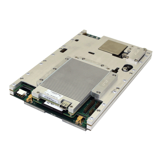
Data rates up to 37 Mbps Figure 1-1. DMD1050TS Satellite Board Modem (Top View) The DMD1050TS remote accessibility rivals all others in the field. Remote control is via Radyne Link Level Protocol (RLLP), Ethernet 100 Base-T SNMP and Web Browser. It includes control of all the modem's features, plus software maintenance. -
Page 26: Dmd1050Ts Configurations
DMD1050T, DMD2050, DMD50, DMD20 and the DISA-certified, MIL-188-165 compliant DMD15L, for seamless substitution and addition to existing systems. Compatibility with the Viasat MD1366 EBEM modem is also provided. The DMD1050TS offers built in standard interfaces that are selectable from MIL-188-114A and a Dual Port Ethernet Bridge. DMD1050TS Configurations You can configure the DMD1050TS in different ways: •... -
Page 27: Chapter 2. Installation
Save the packing material for storage or reshipment purposes. Inspect the equipment for any possible damage incurred during shipment. Note: If damage is evident, contact the carrier and Comtech EF Data immediately and submit a damage report. Check the contents against the packing list to verify completeness of the shipment. -
Page 28: Installation Requirements
Make sure that all of the shipped items are in the container. Installation Considerations The operating temperature range for the DMD1050TS is 0 to +60°C (+32 to +140°F). It is designed to be conduction cooled. Heat spreaders conduct from heat generating components to the edges of the assembly. -
Page 29: Tools Required
Do not put Modems immediately above or below a high electromagnetic field (EMF) generator, to prevent output signal corruption and incorrect receive operation. Do not install the DMD1050TS in an unprotected outdoor location, where there is direct contact with rain, snow, wind or sun. -
Page 30: Dmd1050Ts Initial Configuration Check
Data Interface) before you install the mating connectors. Failure to do this can cause damage to the Data Interface. The DMD1050TS is shipped from the factory with preset factory defaults. Upon initial power-up, do a user check to examine the shipped modem configuration. -
Page 31: Modulator Checkout
DMD1050TS Satellite Modem Board Revision 1 Modulator Checkout The Modulator checkout descriptions assume that the DMD1050TS is installed in a suitable location with clean, stable DC power. Make sure that DC spikes do not occur during initial power 2.6.1 Initial Power-Up CAUTION –... -
Page 32: M&C Terminal Setup
DMD1050TS Satellite Modem Board Revision 1 2.6.3 M&C Terminal Setup You can do the initial field checkout of the modem in Terminal Mode. The Terminal Mode gives you full screen access to the modem’s parameters. However, it requires a separate terminal or computer running a terminal program such as Hyper-terminal, and connection to the applicable pins on the Remote Port connector (J3). -
Page 33: Chapter 3. Theory Of Operation
DMD1050TS Satellite Modem Board Revision 1 Chapter 3. Theory of Operation DMD1050TS Hardware The DMD1050TS uses three printed circuit cards in its design. The standard configuration consists of: • L-Band Assembly • Digital Baseband Assembly • FIPs 140-2 TRANSEC Security module This configuration includes built in data interfaces and several software upgrade options. -
Page 34: L-Band Printed Circuit Card
DMD1050TS Satellite Modem Board Revision 1 3.1.1 L-Band Printed Circuit Card The L-Band/IF Printed Circuit Card consists of: • Analog modulation function • Analog complex down conversion • Two wide-band digital synthesizers The block diagram of the L-Band Assembly is shown in Figure 3-2. -
Page 35: Baseband Processing Printed Circuit Card
FPGA, aside from the amount of Flash memory available to the system microprocessor for storage of configuration files. The DMD1050TS Baseband Processing Printed Circuit Card provides a flexible architecture that allows many different modes of terrestrial and satellite framing, various Forward Error Correction (FEC) options, digital voice processing and several different modulation/demodulation formats. -
Page 36: Fips 140 Level 2 Transec Security Module
Security (TRANSEC) Security Module in standalone operation with the DMD1050TS Modem. The Federal Information Processing Standards (FIPS) Module is a standalone, independently- certified optional card that is secured to the DMD1050TS baseband processing card. It does bulk encryption and decryption of traffic over the satellite, using the AES-256 algorithm. -
Page 37: Figure 3-4. Dmd1050Ts Fips 140 Level 2 Transec Processing Module Block Diagram
DMD1050TS Satellite Modem Board Revision 1 Figure 3-4. DMD1050TS FIPS 140 Level 2 TRANSEC Processing Module Block Diagram Theory of Operation 3–5 MN-DMD1050TS... -
Page 38: Dmd1050Ts Functional Block Diagram
DMD1050TS Satellite Modem Board Revision 1 DMD1050TS Functional Block Diagram Figure 3-5 shows the DMD1050TS Functional Blocks. The modem is shown in a typical application with customer data, Tx/Rx RF equipment and an antenna. 3.2.1 Baseband Processing The Baseband Processor does all of the functions required for an Intelsat Buisiness Service (IBS) / Intermediate Data Rate (IDR) Framing Unit, a Reed-Solomon (R-S) Codec. -
Page 39: Rx Baseband Processing
DMD1050TS Satellite Modem Board Revision 1 Figure 3-5. DMD1050TS Universal Satellite Modem Functional Block Diagram 3.2.3 Rx Baseband Processing The Receive Processor performs the inverse function of the Transmit Processor. Data received from the satellite passes through the BB Loopback Circuit to the R-S decoder to the deframer. -
Page 40: Fips Module Processing
Revision 1 3.2.4 FIPs Module Processing The FIPs Module on the DMD1050TS does bulk encryption and decryption of traffic over the satellite using the AES-256 algorithm. When operating in Non-STANAG 4486 (Enhanced Bandwidth Efficient Modem (EBEM)) modes, the DMD1050TS AES encryption uses Code Block Chaining (CBC) mode to do the encryption and decryption of the user data. -
Page 41: Monitor & Control (M&C)
The baud rate and protocol can be selected from the Web Browser. 3.3.2 Terminal Mode Control The DMD1050TS Terminal Mode Control allows the use of an external terminal or computer to monitor and control the modem from a full screen, interactive presentation operated by the modem itself. -
Page 42: Modem Setup For Terminal Mode
Mode parameter to Terminal. Then, set the Modem Port, Term Baud and Emulation Parameters as desired. Next, connect a terminal to the J1connector. All operating software for the Terminal Mode is contained in the DMD1050TS modem internal control software. These actions initiate full screen terminal mode printing and redrawing of the full screen: a break signal on the communications line, pressing ESC on the terminal, or Power On of the modem. -
Page 43: Modem Remote Communications (Radyne Link Level Protocol)
This port is dedicated for Ethernet Communications supporting SNMP, FTP and Web Browser to the DMD1050TS base modem, and Secure HTTP (HTTPS) independently to the FIPs module. The port is configured for 100 Base-T communications protocols. The Ethernet M&C interface uses a standard RJ45 Male connector. -
Page 44: Ethernet Data Interface - (J10)
Select Ethernet as the terrestrial interface, and connect the LAN into any of the two RJ-45 connectors on the unit. The DMD1050TS Ethernet Interface maintains backward compatibility with all of these products: • DMD20/DMD20 LBST/DMD50/DMD2050/DMD2050E and the OM20 with High-level Data Link Control (HDLC) selection RADYNE •... -
Page 45: Table 3-1. Dmd1050Ts Hdlc Interoperation
DMD1050TS Satellite Modem Board Revision 1 Table 3-1. DMD1050TS HDLC Interoperation Modem Model Ethernet Interface HDLC DMD20 PLR5171 10/100 Radyne DMD20 LBST PLR5171 10/100 Radyne DMD20 PLR5497 10/100 Radyne DMD1050 Legacy Radyne DMD1050T Radyne DMD20 PLR5584 10/100/1000 Radyne DMD20 LBST... - Page 46 DMD1050TS Satellite Modem Board Revision 1 3.7.1.3 Half-Duplex Flow Control In half-duplex mode, the unit uses industry standard backpressure to support flow control: • When available buffer space is almost gone, the modem causes a collision on the input port when it senses an incoming packet. This collision causes the transmitting station to back off, and retry the transmission.
-
Page 47: Figure 3-6. Point-To-Multipoint With Daisy Chaining
Revision 1 3.7.1.8 Set Up the DMD1050TS Ethernet Bridge to Operate Like a FIFO In certain circumstances, it can be desirable to have the Ethernet interface operate in a FIFO-like manner, with no reordering of packets. This can be established by using a single port on the Ethernet interface, and setting the Ethernet QoS Type to Port Based, and the Ethernet QoS Queue to Strict Priority. - Page 48 DMD1050TS Satellite Modem Board Revision 1 3.7.1.9 Packet Statistics These statistics are available from the Monitor Menu, when the Ethernet Data Interface is selected. • Total Packets: shows the total number of Ethernet packets received from the satellite • Error Packets: shows the total number of Ethernet packets received from the satellite that had errors •...
-
Page 49: Internal Clock
DMD1050TS Satellite Modem Board Revision 1 Internal Clock The time and date are used to time-stamp system events. You can change the time and date via the Web Browser. Loopback Features (Terrestrial & IF) CAUTION: DATA LOSS POSSIBLE To run any type of data test with an Ethernet interface, you must use two modems connected back-to-back. -
Page 50: Figure 3-7. Loopback Functional Block Diagram
DMD1050TS Satellite Modem Board Revision 1 Figure 3-7. Loopback Functional Block Diagram Theory of Operation 3–18 MN-DMD1050TS... -
Page 51: Figure 3-8. Loopback Functional Block Diagram
DMD1050TS Satellite Modem Board Revision 1 Figure 3-8. Loopback Functional Block Diagram Figure 3-9. Loopback Functional Block Diagram Theory of Operation 3–19 MN-DMD1050TS... -
Page 52: Dmd1050Ts Clocking Options
Revision 1 3.10 DMD1050TS Clocking Options The DMD1050TS supports several clocking options that can be recovered from the satellite or the terrestrial links. The clocking options allow you to decide which clock best fits the application. Figure 3-10 shows a diagram on how the modem processes the clocks for the Tx Clock source and the Rx Buffer Clock source. -
Page 53: Rx Buffer Clock Options
3.10.2 Rx Buffer Clock Options The DMD1050TS supports several Rx Buffer clock options that can be recovered from the satellite, from terrestrial links or internally. The clocking options allow you to decide which clock best fits the application. Figure 3-10 shows how the modem processes the clocks for the Tx Clock and the Rx Buffer Clock. -
Page 54: Ethernet Data Interface
This is not actually a clock, but does have some clocking implications. When the external reference is used, the master oscillator in the DMD1050TS is locked to the external reference, and the internal accuracy and stability of the DMD1050TS assumes that of the External Reference. -
Page 55: Reed-Solomon (R-S) Codec
3.12.1 R-S Operation in the DMD1050TS When the R-S Codec is enabled, data is fed to the R-S Encoding Section of the DMD1050TS, where it is scrambled, formed into blocks, R-S encoded and interleaved. Unique words are added so that the blocks can be reformed in the Receiving Modem (See Figure 3-11 and Figure 3-12). -
Page 56: Table 3-2. R-S Codes
DMD1050TS Satellite Modem Board Revision 1 Table 3-2. R-S Codes Maximum Data Rate R-S Code Bandwidth Expansion Interleaving Service Type R-S Codec (Kbps) (n, k, t) [(n/k) -1 ] Depth Delay (ms) (126, 112, 7) 0.125 (126, 112, 7) 0.125 (126, 112, 7) 0.125... -
Page 57: Dmd1050Ts Automatic Uplink Power Control (Aupc) Operation
DMD1050TS Satellite Modem Board Revision 1 3.13 DMD1050TS Automatic Uplink Power Control (AUPC) Operation The modem has an optional, built-in provision for AUPC. AUPC is useful when operating power levels are affected by environmental changes in the atmosphere. AUPC attempts to adjust local power output to maintain a constant Eb/No at the receiver location. -
Page 58: Ef Aupc
DMD1050TS Satellite Modem Board Revision 1 3.13.2 EF AUPC In this case, Target Eb/No indicates the local unit wants the remote unit to maintain a power level sufficient to provide the local Eb/No value. The EF AUPC can be set to operate on either or both directions of a link, but always requires a bi-directional channel. -
Page 59: Table 3-3. Local Aupc Functions
DMD1050TS Satellite Modem Board Revision 1 EF AUPC also gives some control over the rate of power change; while Radyne and Near Side AUPC use optimized rates for rain fade compensation. Table 3-3. Local AUPC Functions Function AUPC Available Options... -
Page 60: Table 3-4. Remote Aupc Functions (Ef Aupc Only)
DMD1050TS Satellite Modem Board Revision 1 Table 3-4. Remote AUPC Functions (EF AUPC Only) Function AUPC Available Options Description AUPC MODE Disable, EFDATA Enables/Disables the AUPC to function remotely LOOPBACK Enabled/Disabled Loop back test over satellite link Tx 2047 TEST... -
Page 61: Asynchronous Overhead Operation (J3)
DMD1050TS Satellite Modem Board Revision 1 3.14 Asynchronous Overhead Operation (J3) This port is dedicated for ES-ES Communications as well. You can configure the port for several Asyncronous communications protocols. Protocols supported are Standard IBS ES-ES, Enhancd Asyncronous and SCC. Overhead data to/from the UIM is routed to/from the framer/deframer. -
Page 62: Table 3-5. Pin Assignments
DMD1050TS Satellite Modem Board Revision 1 Table 3-5. Pin Assignments Kbps Baud Rate Example for Standard IBS Kbps Baud Rate Example for Enhanced Mode 19.2 1200 2400 4800 4800 1024 9600 1152 9600 1280 9600 1408 9600 1536 9600 1664... -
Page 63: Standard Ibs Es-To-Es Mode
Because this mode changes the use of many of the framed non-data bits, this mode is usable only when the DMD1050TS is at both ends of a link. In this mode, the overhead signaling bytes 16 and 48 can be used to implement a significantly higher speed ES-to-ES Data Channel under software control. -
Page 64: Satellite Control Channel (Scc) - J3
DMD1050TS Satellite Modem Board Revision 1 3.17 Satellite Control Channel (SCC) – J3 The SCC format uses a variable overhead rate to transmit an asynchronous data channel, in addition to the normal data channel. The SCC asynchronous mode implemented on the DMD20 is Pass Thru Mode. -
Page 65: Aggregate Data Rate
DMD1050TS Satellite Modem Board Revision 1 Example 2: 1 to 1 Control Ratio The Control Ratio of the receiving units must match the Control Ratio of the transmitting unit. 3.17.2 Aggregate Data Rate Aggregate Data Rate = User Data Rate + In-Band Rate + Synchronizing Overhead Rate Because SCC must adjust the overhead so that there are an equal number of user data bits in each slot, the synchronizing overhead cannot be calculated easily. -
Page 66: Overhead Rate Comparison
DMD1050TS Satellite Modem Board Revision 1 3.17.3 Overhead Rate Comparison The SCC Overhead Ratio varies, depending on the User Data Rate, the In-Band Rate and the Control Ratio. This gives SCC the advantage of lower overhead rates when compared to IBS, which has a fixed overhead ratio of 16/15 or 1.067. -
Page 67: Scc Overhead Channel Setup
DMD1050TS Satellite Modem Board Revision 1 3.17.5 SCC Overhead Channel Setup Set the Framing Mode (located under Mod and Demod Data Menus) to SCC. After doing this, two new menus show to the right of the Framing Menu, for both the Mod... -
Page 68: Table 3-8. Scc Overhead Chart Examples (Viterbi 3/4 W/V.35 Scrambler)
DMD1050TS Satellite Modem Board Revision 1 Table 3-8. SCC Overhead Chart Examples (Viterbi 3/4 w/V.35 Scrambler) Modem Data Rate SCC Control Channel In-Band Overhead Rate Symbol Rate Kbps Rate Setting 6800 6700 6667 6650 6641 6634 6629 9600 19200 9600... -
Page 69: Ebem Framing Unit
Revision 1 3.18 EBEM Framing Unit The DMD1050TS EBEM framing Unit provides the ability to multiplex both Serial (MIL-STD-188- 114A or High Speed Serial Interface (HSSI)) with Bridged Ethernet payload, overhead and embedded channel data within the over-the-air transport stream. -
Page 70: Stanag Turbo Coding
3.19 STANAG Turbo Coding The DMD1050TS provides STANAG Turbo coding FEC for all specified baseband data rates (64 kbps to 20.0 Mbps) and modulation formats (BPSK, QPSK, 8-PSK, and 16-APSK) with the following code rates: None, 1/2, 2/3, 3/4, 7/8, or 19/20. A decoding function for all Turbo encoded data is also provided. -
Page 71: Fips Transec Module
3.20 FIPS TRANSEC Module The DMD1050TS FIPS Security Module provides bulk encryption and decryption of traffic over the satellite that conforms to Security Level 2 as defined in FIPS PUB 140-2 using National Institute of Standards and Technology (NIST) approved 256-bit Advanced Encryption Standard (AES) encryption. -
Page 72: Figure 3-13. Traffic Encryption Key Negotiation
DMD1050TS Satellite Modem Board Revision 1 Figure 3-13. Traffic Encryption Key Negotiation Theory of Operation 3–40 MN-DMD1050TS... -
Page 73: Figure 3-14. Traffic Decryption Key Negotiation
DMD1050TS Satellite Modem Board Revision 1 Figure 3-14. Traffic Decryption Key Negotiation 3.20.1.2 Key Agreement Algorithm The key agreement algorithm used to negotiate a shared secret is the Ephemeral Unified Model, Elliptic Curve Cryptography Cofactor Diffie-Hellman C(2,0,ECC CDH) as specified in the elliptic curve parameters section of NIST SP 800-56A(3). - Page 74 DMD1050TS Satellite Modem Board Revision 1 3.20.1.3 Accessing Encryption/Decryption Features The DMD2050E enables the Crypto Officer to administer the FIPs module through authentication. The Crypto Officer Administrator can: • Load software • Load key material • Configure operating parameters •...
-
Page 75: Dmd1050Ts Id Codes (Feature Upgrades)
The Strap Code is a quick set key that sets many of the modem parameters. For quick setup of the DMD1050TS, Strap Codes are very helpful. When a Strap Code is entered, the modem is configured automatically for the code’s corresponding data rate, overhead, code rate, framing, scrambler type and modulation. - Page 76 DMD1050TS Satellite Modem Board Revision 1 BLANK PAGE Theory of Operation 3–44 MN-DMD1050TS...
-
Page 77: Chapter 4. Rear Panel Interface
All DMD1050TS connections are made to labeled connectors located on the Modem Board. See Figure 4-1, Figure 4-2, Figure 4-3, and Figure 4-4. You must use the correct connector to make any connection to the DMD1050TS. See Appendix E for information about the connectors that are used with the DMD1050TS. -
Page 78: Figure 4-1. Dmd1050Ts Front View
DMD1050TS Satellite Modem Board Revision 1 Pin 1 BUC & LNB COMPACT INPUT POWER OPT (F) FLASH CARD OPT (F) RX L-BAND TX L-BAND Figure 4-1. DMD1050TS Front View Figure 4-2. DMD1050TS Rear View Rear Panel Interface 4–2 MN-DMD1050TS... -
Page 79: Figure 4-3. Rf Board (Pl-0021834)
DMD1050TS Satellite Modem Board Revision 1 J2 SMA J1 SMA OPT (F) COMPACT OPT (F) RX L-BAND FLASH CARD TX L-BAND HIGH TWIN RJ45 RJ45 STABILITY INPUT POWER ETHERNET M&C OSCILLATOR FEMALE DATA Figure 4-3. RF Board (PL-0021834) Rear Panel Interface 4–3... -
Page 80: Figure 4-4. Baseband Modem Board (Pl-0022534)
DMD1050TS Satellite Modem Board Revision 1 Figure 4-4. Baseband Modem Board (PL-0022534) Rear Panel Interface 4–4 MN-DMD1050TS... -
Page 81: Compact Flash (J6)
DMD1050TS Satellite Modem Board Revision 1 Compact Flash (J6) A minimum 256 Mbit flash memory card stores all the modem M&C and operational data. It must be installed when the modem is operating. Power Input (J16) The Input DC Power for the modem board requires: •... -
Page 82: Tx L-Band If (J1)
DMD1050TS Satellite Modem Board Revision 1 4.5.2 TX L-Band IF (J1) The Transmit IF Output Port is a 50 Ohm SMA Female Connector that is used for L-Band IF. The power level is programmable from 0 to -25 dBm, in 0.1 dBm steps. -
Page 83: Figure 4-5. Default/Shorting Plug (Jp1 And Jp2)
DMD1050TS Satellite Modem Board Revision 1 Table 4-4. Default/Reset connections: 3-Pin male Connector (JP1 & JP2) Install Shunt/Jumper Between Pins No. Pin 1 & 2 Figure 4-5. Default/Shorting Plug (JP1 and JP2) Rear Panel Interface 4–7 MN-DMD1050TS... -
Page 84: Mil-188-114A (J4)
RJ-45 connector. 4.5.8 Ethernet Data Interface (J10) The DMD1050TS Ethernet Data Interface provides two RJ-45, Auto-Crossover and Auto- Sensing, 10/100 Ethernet Data Ports. The physical interfaces are twin female RJ-45 connectors. Rear Panel Interface 4–8... -
Page 85: Simple Key Loader (J17)
Revision 1 4.5.9 DS-101 Simple Key Loader (J17) The DMD1050TS Simple Key Loader (SKL) Interface J17 can be used to connect an SKL AN/PYQ-10 Electronic Key Management System (EKMS) key management device. The physical interface is a 3-Pin Male Header Mfg (FCI) P/N: 68771-203HLF. - Page 86 DMD1050TS Satellite Modem Board Revision 1 BLANK PAGE Rear Panel Interface 4–10 MN-DMD1050TS...
-
Page 87: Chapter 5. Maintenance And Troubleshooting
Troubleshooting First, examine all interface signals for correct operation. If a unit is suspected of a defect in field operations after that, replace the unit with another known working DMD1050TS. If a problem still exists, examine the wiring or power. -
Page 88: Alarm Faults
DMD1050TS Satellite Modem Board Revision 1 5.2.1 Alarm Faults 5.2.1.1 Major Tx Alarms Alarm Possible Cause FPGA CFG Shows a transmit FPGA hardware failure DSP CFG Shows a transmit FPGA failure SCT Clock PLL Shows that the Tx SCT Clock PLL is not locked. This alarm flashes during certain parameter changes. - Page 89 DMD1050TS Satellite Modem Board Revision 1 5.2.1.4 Minor Rx Alarms Alarm Possible Cause BUFF UNDERFLOW Shows that a Doppler Buffer underflow has occurred BUFF NEAR EMPTY Shows that the Doppler Buffer is about to underflow BUFF NEAR FULL Shows that the Doppler Buffer is about to overflow...
-
Page 90: Alarm Masks
Revision 1 5.2.2 Alarm Masks CAUTION: DATA LOSS POSSIBLE Masked alarms can cause undesirable modem performance. The DMD1050TS does a high degree of self-monitoring and fault isolation. The alarms for these faults are separated into categories: • Active Alarms •... -
Page 91: Chapter 6. Technical Specifications
DMD1050TS Satellite Modem Board Revision 1 Chapter 6. Technical Specifications Data Rates Limits 6.1.1 Non-EBEM Modes Non-EBEM Modes Modulation Code Rate Min Data Rate (Kbps) Max Data Rate (Mbps) BPSK Uncoded 10.0 BPSK 5/16 3.125 BPSK 21/44 4.773 BPSK BPSK BPSK 8.75... -
Page 92: Ebem Modes
DMD1050TS Satellite Modem Board Revision 1 6.1.2 EBEM Modes EBEM Modes Modulation Code Rate Min Data Rate (Kbps) Max Data Rate (Mbps) BPSK 4.965 BPSK 6.614 BPSK 7.436 BPSK 8.673 BPSK 19/20 9.412 QPSK 9.905 QPSK 13.180 QPSK 14.811 QPSK 17.253... - Page 93 DMD1050TS Satellite Modem Board Revision 1 Non-DVB Modes Modulation Code Rate Min Data Rate Max Data Rate BPSK EBEM TURBO 3/4 64000 7436434 BPSK EBEM TURBO 7/8 64000 8673111 BPSK EBEM TURBO 19/20 64000 9412035 QPSK NONE 9600 20000000 QPSK...
-
Page 94: Dvb Modes
DMD1050TS Satellite Modem Board Revision 1 Non-DVB Modes Modulation Code Rate Min Data Rate Max Data Rate 8QAM TPC 3/4 10800 20000000 8QAM TPC 7/8 12600 20000000 8QAM LDPC 2/3 9600 20000000 8QAM LDPC 3/4 10800 20000000 16QAM VIT 3/4... - Page 95 DMD1050TS Satellite Modem Board Revision 1 188 Mode Modulation Code Rate Min Data Rate Max Data Rate BPSK VIT 1/2 2400 4607843 BPSK VIT 2/3 2950 6143790 BPSK VIT 3/4 3318 6911764 BPSK VIT 5/6 3687 7679738 BPSK VIT 7/8...
-
Page 96: Modulator
DMD1050TS Satellite Modem Board Revision 1 Modulator Modulation BPSK, QPSK, and OQPSK, 8PSK, 8QAM, 16QAM,16APSK L-Band Tuning 950 to 2050 MHz in 1 Hz Steps Range Impedance SMA, 50 Ohm or F-Type 75 Ohm (Optional) Connector SMA, or F-Type (Optional) Return Loss SMA 2.0:1... -
Page 97: Demodulator
DMD1050TS Satellite Modem Board Revision 1 Demodulator Demodulation BPSK, QPSK, and OQPSK, 8PSK, 8QAM, 16QAM, 16APSK IF Tuning L-Band Tuning Range 950 to 2050 MHz in 1 Hz Steps Range Impedance SMA, 50 Ohm, F-Type 75 Ohm (Optional) Connector SMA, F-Type (Optional) Return Loss SMA 2.0:1... -
Page 98: Plesiochronous Buffer
DMD1050TS Satellite Modem Board Revision 1 Plesiochronous Buffer Size 0 msec to 64 msec Centering Automatic on Underflow/Overflow Centering Modes IBS: Integral Number of Frames IDR: Integral Number of Multi-Frames Clock External, Rx Recovered or SCT (Internal) Monitor and Control Ethernet 10/100 Base-T/Web Browser/SNMP, Remote RS-485/Terminal RS-232. -
Page 99: Ber Specifications
DMD1050TS Satellite Modem Board Revision 1 BER Specifications 6.9.1 BER Performance (Viterbi) 1E-1 B/O/QPSK Uncoded Theory 1E-2 Viterbi Decoder 1E-3 Typical Performance 1E-4 1E-5 1E-6 Specification 1/2 Rate Specification 3/4 1E-7 Rate Specification 7/8 1E-8 Rate 1E-9 Eb/No in dB Figure 6-1. -
Page 100: Ber Performance (Sequential)
DMD1050TS Satellite Modem Board Revision 1 6.9.2 BER Performance (Sequential) 1E-1 B/O/QPSK Uncoded Theory 1E-2 Sequential Decoder Typical Performance 1E-3 1E-4 1E-5 1E-6 Specification 1/2 Rate 1E-7 Specification 3/4 Rate 1E-8 Specification 7/8 Rate 1E-9 Eb/No in dB Figure 6-2. B/0/QPSK BER Performance (Sequential) Note: Eb/No values include the effect of using differential decoding and v.35 descrambling. -
Page 101: Ber Performance (Viterbi - W/Reed-Solomon)
DMD1050TS Satellite Modem Board Revision 1 6.9.3 BER Performance (Viterbi - w/Reed-Solomon) 1E-1 B/O/QPSK Uncoded Theory 1E-2 Typical Viterbi Decoder Reed Performance Solomon 1E-3 1E-4 1E-5 1E-6 Specification 1/2 Rate 1E-7 Specification 7/8 Rate Specification 3/4 Rate 1E-8 1E-9 Eb/No in dB Figure 6-3. -
Page 102: Ber Performance (8Psk Trellis)
DMD1050TS Satellite Modem Board Revision 1 6.9.4 BER Performance (8PSK Trellis) 1E-1 8PSK Uncoded Theory Trellis 1E-2 Decoder 1E-3 Typical Performance 1E-4 1E-5 1E-6 Specification 2/3 Rate 1E-7 Specification 2/3 Rate w/RS 1E-8 1E-9 Eb/No in dB Figure 6-4. 8PSK BER Performance (Trellis) Note: Eb/No values include the effect of using differential decoding and v.35 descrambling. -
Page 103: Ber Performance (16Qam Viterbi)
DMD1050TS Satellite Modem Board Revision 1 6.9.5 BER Performance (16QAM Viterbi) 1E-1 16QAM Uncoded Theory Viterbi 1E-2 Decoder 1E-3 Typical Performance 1E-4 1E-5 1E-6 Specification 3/4 Rate 1E-7 Specification 7/8 Rate 1E-8 1E-9 Eb/No in dB Figure 6-5. 16QAM BER Performance (Viterbi) Note: Eb/No values include the effect of using differential decoding and v.35 descrambling. -
Page 104: Ber Performance (16Qam Viterbi W/Reed-Solomon)
DMD1050TS Satellite Modem Board Revision 1 6.9.6 BER Performance (16QAM Viterbi w/Reed-Solomon) 1E-1 16QAM Uncoded Theory 1E-2 Viterbi Decoder - Reed Solomon Typical 1E-3 Performance 1E-4 1E-5 1E-6 Specification 1E-7 3/4 Rate w/RS Specification 7/8 Rate w/RS 1E-8 1E-9 Eb/No in dB Figure 6-6. -
Page 105: Ber Performance ((O)Qpsk Turbo)
DMD1050TS Satellite Modem Board Revision 1 6.9.7 BER Performance ((O)QPSK Turbo) 1E-1 B/O/QPSK Uncoded Theory 1E-2 Turbo Decoder Specification 3/4 Rate 1E-3 1E-4 Specification Specification 1/2 Rate 7/8 Rate 1E-5 1E-6 1E-7 Typical Performance 1E-8 1E-9 Eb/No in dB Figure 6-7. (O)QPSK BER Performance (Turbo) Technical Specifications 6–15... -
Page 106: Ber Performance (Bpsk Turbo)
DMD1050TS Satellite Modem Board Revision 1 6.9.8 BER Performance (BPSK Turbo) 1E-1 B/O/QPSK Uncoded Theory 1E-2 Turbo Decoder 1E-3 1E-4 Specification 21/44 Rate 1E-5 Specification 1E-6 5/16 Rate 1E-7 Typical Performance 1E-8 1E-9 Eb/No in dB Figure 6-8. BPSK BER Performance (Turbo) Technical Specifications 6–16... -
Page 107: Ber Performance (8Psk Turbo)
DMD1050TS Satellite Modem Board Revision 1 6.9.9 BER Performance (8PSK Turbo) 1E-1 8PSK Uncoded Theory 1E-2 Turbo Decoder Specification 3/4 Rate 1E-3 Specification 7/8 Rate 1E-4 Typical Performance 1E-5 1E-6 1E-7 1E-8 1E-9 Eb/No in dB Figure 6-9. 8PSK BER Performance (Turbo) Technical Specifications 6–17... -
Page 108: Ber Performance (16Qam Turbo)
DMD1050TS Satellite Modem Board Revision 1 6.9.10 BER Performance (16QAM Turbo) 1E-1 16QAM Uncoded Theory Turbo Decoder 1E-2 Specification 3/4 Rate Specification 7/8 1E-3 Rate 1E-4 Typical Performance 1E-5 1E-6 1E-7 1E-8 1E-9 Eb/No in dB Figure 6-10. 16QAM BER Performance (Turbo) Technical Specifications 6–18... -
Page 109: B/O/Qpsk Ber Performance (Ldpc)
DMD1050TS Satellite Modem Board Revision 1 6.9.11 B/O/QPSK BER Performance (LDPC) 1E-1 B/O/QPSK Uncoded Theory 1E-2 LDPC Decoder 1E-3 Specification 1/2 Rate Specification 2/3 Rate 1E-4 Specification 3/4 Rate 1E-5 Typical Performance 1E-6 1E-7 1E-8 1E-9 Eb/No in dB Figure 6-11. B/O/QPSK BER Performance (LDPC) Technical Specifications 6–19... -
Page 110: 8Psk/8Qam Ber Performance (Ldpc)
DMD1050TS Satellite Modem Board Revision 1 6.9.12 8PSK/8QAM BER Performance (LDPC) 1E-1 8PSK Uncoded Theory 1E-2 LDPC Decoder 1E-3 1E-4 Typical Performance 8QAM Rate 2/3 Specification 1E-5 8PSK Rate 2/3 Specification 1E-6 8PSK/8QAM Rate 3/4 Specification 1E-7 1E-8 1E-9 Eb/No in dB Figure 6-12. -
Page 111: 16Qam Ber Performance (Ldpc)
DMD1050TS Satellite Modem Board Revision 1 6.9.13 16QAM BER Performance (LDPC) 1E-1 16QAM Uncoded Theory 1E-2 LDPC Decoder 1E-3 1E-4 Typical Performance Specification 1E-5 3/4 Rate 1E-6 1E-7 1E-8 1E-9 Eb/No in dB Figure 6-13. 16QAM BER Performance (LDPC) Technical Specifications 6–21... -
Page 112: Ber Performance B/O/Qpsk (Milstd 188-165B Or Stanag) Turbo
DMD1050TS Satellite Modem Board Revision 1 6.9.14 BER Performance B/O/QPSK (MILSTD 188-165B or STANAG) Turbo 1E-1 B/O/QPSK Uncoded Theory Specification 1/2 Rate 1E-2 Specification MILSTD 188-165B 2/3 Rate or STANAG Decoder 1E-3 Specification 3/4 Rate Specification 1E-4 7/8 Rate Specification... -
Page 113: Ber Performance 8-Psk (Milstd 188-165B Or Stanag) Turbo
DMD1050TS Satellite Modem Board Revision 1 6.9.15 BER Performance 8-PSK (MILSTD 188-165B or STANAG) Turbo 1E-1 Specification 8PSK Uncoded Theory 1/2 Rate MILSTD 188-165B Specification 1E-2 2/3 Rate or STANAG Decoder Specification 3/4 Rate Specification 7/8 Rate 1E-3 Specification 19/20 Rate... -
Page 114: Ber Performance 16Apsk (Milstd 188-165B Or Stanag) Turbo
DMD1050TS Satellite Modem Board Revision 1 6.9.16 BER Performance 16APSK (MILSTD 188-165B or STANAG) Turbo 1E-1 Specification 16QAM Uncoded Theory 1/2 Rate Specification MILSTD 188-165B 2/3 Rate or STANAG Specification 1E-2 Decoder 3/4 Rate Specification Specification 7/8 Rate 19/20 Rate... -
Page 115: Table 6-1. B/O/Qpsk Ber Performance (Viterbi)
DMD1050TS Satellite Modem Board Revision 1 Table 6-1. B/O/QPSK BER Performance (Viterbi) Specification (dB) Typical (dB) 1/2 Rate 3/4 Rate 7/8 Rate 1/2 Rate 3/4 Rate 7/8 Rate 1E-5 1E-6 1E-7 1E-8 10.2 Table 6-2. B/O/QPSK BER Performance (Sequential) Specification (dB) -
Page 116: Table 6-6. 16Qam Ber Performance (Viterbi W/Rs)
DMD1050TS Satellite Modem Board Revision 1 Table 6-6. 16QAM BER Performance (Viterbi w/RS) Specification (dB) Typical (dB) 3/4 Rate 7/8 Rate 3/4 Rate 7/8 Rate 1E-5 1E-6 10.2 1E-7 10.4 1E-8 10.7 Table 6-7. (O)QPSK BER Performancfe (Turbo) Specification (dB) -
Page 117: Table 6-11. B/O/Qpsk Ber Performance (Ldpc)
DMD1050TS Satellite Modem Board Revision 1 Table 6-11. B/O/QPSK BER Performance (LDPC) Specification (dB) Typical (dB) 1/2 Rate 2/3 Rate 3/4 Rate 1/2 Rate 2/3 Rate 3/4 Rate 1E-5 1E-6 1E-7 1E-8 Table 6-12. 8PSK / 8-QAM Rate BER Performance (LDPC) -
Page 118: Table 6-15. B/O/Qpsk Ber Performance (Mil Std 188-165B Or Stanag) Turbo
DMD1050TS Satellite Modem Board Revision 1 Table 6-15. B/O/QPSK BER Performance (MIL STD 188-165B or STANAG) Turbo 16 K Block Specification (dB) Typical (dB) 19/20 19/20 Rate Rate Rate Rate Rate Rate Rate Rate Rate Rate 1E-5 1E-6 2.65 3.15 2.25... -
Page 119: Table 6-17. 16Apsk Ber Performance (Mil Std 188-165B Or Stanag) Turbo
DMD1050TS Satellite Modem Board Revision 1 Table 6-17. 16APSK BER Performance (MIL STD 188-165B or STANAG) Turbo 16 K Block Specification (dB) Typical (dB) 19/20 19/20 Rate Rate Rate Rate Rate Rate Rate Rate Rate Rate 1E-5 10.5 10.2 1E-6 10.7... -
Page 120: Acg Output Voltage
DMD1050TS Satellite Modem Board Revision 1 6.10 ACG Output Voltage The AGC Output Voltage is a function of the Input Power Level in dBm. The AGC Output Voltage is found on the Alarm connector Pin 24 of J2. Figure 6-17. AGC Voltage Monitor Technical Specifications 6–30... -
Page 121: Dmd Input Level Specification
DMD Input Level User Selectable Carrier Input Level Limit Minimum Receive Level (Minor RX Alarm) -100 1,000 10,000 Symbol Rate (kSPS) Lower Input Limit Upper Input Limit Carrier Input Level Limit (Setable) Figure 6-18. DMD1050TS Input Level Specification Technical Specifications 6–31 MN-DMD1050TS... - Page 122 DMD1050TS Satellite Modem Board Revision 1 BLANK PAGE Technical Specifications 6–32 MN-DMD1050TS...
-
Page 123: Chapter 7. Web Browser
FIPS TRANSEC module. The Web applications are described as well. Configuring Your PC Get access to the Web Browser interface through the RJ45 (J11), MagJack on the DMD1050TS. You must use Microsoft Internet Explorer 6 or greater to use the Web Browser menus. -
Page 124: Screen Areas
A content page shows under the navigation menus. At the top of the page, breadcrumb links remind you how to get to the page. 7.3.3 Light Emitting Diode (LED) Indicators LEDs show the operational status of the DMD1050TS. The LED colors have these meanings: • Green means operations are normal •... -
Page 125: Table 7-1. Led Indicators
DMD1050TS Satellite Modem Board Revision 1 Table 7-1. LED Indicators Color Function Modem LED Lights Power Green The unit is on. Fault A hardware fault exists in the unit. A condition or event occurred, and is stored in memory. See the events from the GUI or in... -
Page 126: Introduction Page
DMD1050TS Satellite Modem Board Revision 1 Introduction Page Figure 7-5. Introduction Page Example This page shows when the web browser starts. The bottom of the page has links for Technical Specifications, Product Options, Troubleshooting, About Us, and Contact us. The Introduction page gives an overview of the product. It has no configurable items. The main menus and submenus are: •... -
Page 127: Login Screen
Figure 7-6. Login Screen Example The Login screen shows when you click any of these tabs: Password Setup, IP Administration or Monitor & Control. Log in, using the correct User Name and Password. The DMD1050TS is configured initially with these defaults: User Name:... -
Page 128: Password Setup
DMD1050TS Satellite Modem Board Revision 1 Password Setup Click Password Setup for the Access page to automatically open. Use the Access page to set up access to the system for multiple operators. 7.5.1 Password Setup | Access Page Figure 7-7. Password Setup | Access Page Example... -
Page 129: Password Setup | Preferences Page
DMD1050TS Satellite Modem Board Revision 1 7.5.2 Password Setup | Preferences Page Figure 7-8. Password Setup | Preferences Page Example Password Setup | Preferences Page User Confirmation DISABLED Enable or disable change confirmation to appear for all • changes made in the Web interface. Bandwidth changes ENABLED •... -
Page 130: Ip Administration
DMD1050TS Satellite Modem Board Revision 1 IP Administration The IP Administration tab offers the following pages to select: • Modem Addressing • Configure Apps • Configure PC 7.6.1 IP Administration | Modem Addressing Page The Modem Addressing page provides instructions to configure the modem. - Page 131 DMD1050TS Satellite Modem Board Revision 1 IP Administration | Modem Addressing Boot Mode DEFAULT: During initialization (boot up), the modem will restore the DEFAULT web setting to the standard IP Mask and addresses supplied by the NON-VOL modem. The modem will be taken off the network and will not be BOOTP accessible.
-
Page 132: Ip Administration | Configure Apps Page
DMD1050TS Satellite Modem Board Revision 1 7.6.2 IP Administration | Configure Apps Page The Configure Apps page provides instructions to configure applications. Figure 7-10. IP Administration | Configure Apps Page Example Web Browser 7–10 MN-DMD1050TS... - Page 133 DMD1050TS Satellite Modem Board Revision 1 IP Administration | Configure Applications SNMP Setup SNMP Version V1 & V2 (default) This selection controls the Simple Network Management • Protocol (SNMP) Version that will be used in messaging • between the equipment and its host.
-
Page 134: Table 7-2. Snmp Parameters
DMD1050TS Satellite Modem Board Revision 1 Table 7-2. SNMP Parameters SNMP VERSION: V1 & V2 TRAP VERSION: V1 AUTHORIZATION: TRAPS OFF RD COMMUNITY: PUBLIC RDWR COMMUNITY: PUBLIC USER 1 USER 2 USER 3 USER 4 Viewer-md5 Viewer-sha Oper-md5 Oper-sha ACCESS GROUP... -
Page 135: Table 7-4. Terminal And Remote Port Parameters
DMD1050TS Satellite Modem Board Revision 1 Table 7-4. Terminal and Remote Port Parameters Type VT100 Baud rate 19200 Interface RS232 Remote control Terminal Web Browser 7–13 MN-DMD1050TS... -
Page 136: Ip Administration | Configure Pc Page
DMD1050TS Satellite Modem Board Revision 1 7.6.3 IP Administration | Configure PC Page The Configure PC page provides instructions to configure the PC. Figure 7-11. IP Administration | Configure PC Page Example Web Browser 7–14 MN-DMD1050TS... -
Page 137: Monitor And Control Menu
DMD1050TS Satellite Modem Board Revision 1 Monitor and Control Menu Use this menu to access all modem functions that are monitored and/or controlled. The Monitor and Control menu has the following submenus: • Transmit • Receive • Interface • Monitor •... - Page 138 DMD1050TS Satellite Modem Board Revision 1 Transmit / General / IF Page Network Specs CLOSED NET Supports IDR and IBS Framing Modes in Closed Net. • IDR (optional) The Network Spec Command sets parameters in the modem • IBS (optional) to meet a set specification.
-
Page 139: Table 7-5. Network Specifications
DMD1050TS Satellite Modem Board Revision 1 Transmit / General / IF Page Spread Factor DISABLED Use to select the Tx spreading factor. This is only selectable • FACTOR x2 if the modem is set to output BPSK+LDPC. • FACTOR, x4 •... -
Page 140: Figure 7-13. Transmit | Data Page Example
DMD1050TS Satellite Modem Board Revision 1 7.7.1.2 Transmit | Data Page Figure 7-13. Transmit | Data Page Example Transmit | Data Page Data Rate (bps) Set the Data Rate in bps steps. See the technical specifications for data rates. Symbol Rate (sps) Use to view the Symbol Rate. - Page 141 • ENABLE This is valid only for Radyne turbo codes TPC.495 and • TPC.793. It is available only for Radyne Legacy Turbo. Contact Comtech EF Data for availability. Differential Coding DISABLE Enable or disable the Differential Encoder. An enabled •...
- Page 142 DMD1050TS Satellite Modem Board Revision 1 Transmit | Data Page Satellite Framing NONE Use to select the framing type. • IDR 96K This is used only with IDR, IBS or Asynchronous Interface. • IBS 1/15 • ASYNC 1/15 • EF AUPC •...
- Page 143 Future option. • Option ENABLE Enable or disable the program to encrypt the transmit • data. This is available when a FIPs Module is installed on the DMD1050TS and the transit FEC is either TPC or LDPC. Web Browser 7–21 MN-DMD1050TS...
-
Page 144: Figure 7-14. Transmit | Reed-Solomon Page Example
DMD1050TS Satellite Modem Board Revision 1 7.7.1.3 Transmit | Reed-Solomon Page These selections are active only when the Reed-Solomon option is installed. Figure 7-14. Transmit | Reed-Solomon Page Example Transmit | Reed-Solomon Page Reed-Solomon DISABLED Enable or disable the R-S Encoder. - Page 145 (Amps) current. BUC Voltage DISABLED Enable or disable the BUC supply voltage. • ENABLED • FSK Comms Not Available on the DMD1050TS. FSK Test Not Available on the DMD1050TS. BUC Address Not Available on the DMD1050TS. Web Browser 7–23 MN-DMD1050TS...
- Page 146 DMD1050TS Satellite Modem Board Revision 1 Transmit | ODU-BUC Page Test Status Not Available on the DMD1050TS. Pass Thru Not Available on the DMD1050TS. Command BUC Output DISABLED Enable or disable the BUC output. • ENABLED • Web Browser 7–24...
- Page 147 DMD1050TS Satellite Modem Board Revision 1 7.7.1.5 Transmit | AUPC Page When modems are configured for Radyne AUPC, the remote Eb/No is displayed in the Monitor Menus. Figure 7-16. Transmit | AUPC Page Example Transmit | AUPC Page LOCAL The LOCAL page section contains the local configuration parameters for the AUPC function.
- Page 148 DMD1050TS Satellite Modem Board Revision 1 Transmit | AUPC Page Nominal Power Use to set the nominal Transmit Power. The nominal 0 to -25 dB • (dBm) transmit power is the default output power level. 0 to -45 dB •...
- Page 149 DMD1050TS Satellite Modem Board Revision 1 Transmit | AUPC Page Tracking Rate 0.5 to 6.0 Read only. • Set the rate at which the commands to increase or decrease Transmit Power are sent. Each command will result in a 0.5 dB increase or decrease in Transmit Power from the remote transmitter.
- Page 150 DMD1050TS Satellite Modem Board Revision 1 Transmit | AUPC Page Remote BER Reports the BER measurement of the receiver 2047 Pattern Test Mode of the remote modem. BER is reported from the 1x10 to 1x10 in tenth decade steps. If the pattern does not synchronize or is out of range, ‘NO DATA’...
- Page 151 DMD1050TS Satellite Modem Board Revision 1 7.7.1.6 Transmit | ITA Page Figure 7-17. Transmit | ITA Page Example Transmit | ITA Page ITA Control DISABLED Enable or disable the ITA function. • ENABLED • Waveform Mask Use to select the mod/code rate.
-
Page 152: Receive Menu
DMD1050TS Satellite Modem Board Revision 1 7.7.2 Receive Menu The Receive menu has the following submenus: • General/IF • Data • Reed Solomon • • ODU-LNB • 7.7.2.1 Receive | General / IF Page Figure 7-18. Receive | General | IF Page Example... - Page 153 Input Level indicator. This is most applicable to the DMD1050 and DMD1050TS card based modems. Eb/No Alarm Thrsh 0.0 to 9.9 dB Use to select an Eb/No level that will trigger an alarm when •...
-
Page 154: Table 7-6. Network Specifications
DMD1050TS Satellite Modem Board Revision 1 Receive | General | IF Page RFM AGC Time Not Applicable. • Constant (msec) Table 7-6. Network Specifications Network Specs Data Rates Framing Scrambler Spectrum MIL 188 165A 9.6 K – 20.0 Mbps None... - Page 155 DMD1050TS Satellite Modem Board Revision 1 7.7.2.2 Receive | Data Page Figure 7-19. Receive | Data Page Example Receive | Data Page Data Rate (bps) Refer to Technical Use the keypad to set the Data Rate in bps steps. See the Specifications.
- Page 156 DMD1050TS Satellite Modem Board Revision 1 Receive | Data Page (B/O/QPSK) LDPC • • • (8PSK / 8QAM) LDPC • • (16QAM) LDPC • (B/Q/8/16APSK) Turbo • • • • 19/20 • None • Rot. Ambiguity 0 (0,0,0) Allows the user to manually resolve the rotational ambiguity •...
- Page 157 DMD1050TS Satellite Modem Board Revision 1 Receive | Data Page Scrambler Control DISABLED Enable or disable the descrambler operation. • ENABLED • Satellite Framing NONE Use to select the Framing Type. This is used only with IDR, • IDR 96K IBS, or Asynchronous Interface.
- Page 158 • EBEM Encryption DISABLE Future option. • ENABLE Use to encrypt the transmit data. This is available when a • FIPs Module is installed on the DMD1050TS and the transit FEC is either TPC or LDPC. Web Browser 7–36 MN-DMD1050TS...
- Page 159 DMD1050TS Satellite Modem Board Revision 1 7.7.2.3 Receive | Reed-Solomon Page Figure 7-20. Receive | Reed-Solomon Page Example Receive | Reed-Solomon Page Reed-Solomon DISABLED Enable or Disable the Reed-Solomon Encoder. • Control ENABLED • Reed-Solomon N Refer to AN177 for Shows the N value in use of the Reed-Solomon codes.
- Page 160 DMD1050TS Satellite Modem Board Revision 1 7.7.2.4 Receive | CNC Page The DMD1050TS does not support CNC. Figure 7-21. Receive | CNC Page Example Receive | CNC Page CnC Mode DISABLED This will always show DISABLED. • Min Search Delay •...
- Page 161 DMD1050TS Satellite Modem Board Revision 1 7.7.2.5 Receive |ODU-LNB Page Figure 7-22. Receive | ODU-LNB Page Example Receive | ODU-LNB Page LO Frequency (MHz) Frequency in MHz Use to enter the Local Oscillator frequency in MHz to cause • the downlink frequency to show correctly.
- Page 162 DMD1050TS Satellite Modem Board Revision 1 7.7.2.6 Receive | ITA Page Figure 7-23. Receive | ITA Page Example Receive | ITA Page ITA Control DISABLED Enable or disable the ITA Control. • ENABLED • Margin (dBm) 0 to 2.00 dB Sets link margin when operating in ITA mode.
- Page 163 DMD1050TS Satellite Modem Board Revision 1 Receive | ITA Page Highlighted Displays the status of each waveform when ITA is engaged. Unattainable • Waveform Mask Only available in EBEM mode. Attainable • Indicate the Current • Following Web Browser 7–41...
-
Page 164: Interface Menu
DMD1050TS Satellite Modem Board Revision 1 7.7.3 Interface Menu The Interface Menu has the following submenus: • TX Setup • RX Setup • General 7.7.3.1 Interface | TX Setup Page Figure 7-24. Interface | TX Setup Page Example Interface | TX Setup Page Circuit ID Use to enter a Tx Circuit Identifier. - Page 165 Read only; shows the ES baud rate in Enhanced Async 150 - 19200 • Mode. ES Bits/Char Read only; shows the 7- or 8-bit data. • • Drop Map Section – Not available on the DMD1050TS Drop Mode Sat Channel Terr TSlot Web Browser 7–43 MN-DMD1050TS...
- Page 166 DMD1050TS Satellite Modem Board Revision 1 7.7.3.2 Interface | RX Setup Page Figure 7-25. Interface | RX Setup Page Example Interface | RX Setup Page Circuit ID Use to enter a Rx Circuit Identifier. Circuits can have an identifier of up to 11 alphanumeric characters, such as DLINK1.
- Page 167 Read only; shows the baud rate in Enhanced Async Mode. • ES Bits/Char Read only: shows 7- or 8-bit data. • • INSERT MAP Section – Not available on the DMD1050TS Insert Mode T1 / E1 Frame Scr Sat Channel Terr TSlot Web Browser 7–45...
- Page 168 DMD1050TS Satellite Modem Board Revision 1 7.7.3.3 Interface | General Page Figure 7-26. Interface | General Page Example Interface | General Page External Frequency Variable through Data Use to enter the external clock frequency in MHz. • (MHz) Rate Reference INTERNAL Use to select the Frequency Reference Source.
-
Page 169: Monitor Menu
DMD1050TS Satellite Modem Board Revision 1 7.7.4 Monitor Menu The Monitor Menu has the following submenus: • VOLTAGES • ETH LINK STATUS • EVENT • 7.7.4.1 Monitor | Voltages Page Figure 7-27. Monitor | Voltages Page Example Monitor | Voltages Page... - Page 170 DMD1050TS Satellite Modem Board Revision 1 Monitor | Voltages Page Es/No (dB) Read only, this shows the estimated Es/No as seen by the demodulator. RX Buffer Reset Use the button to re-center the Doppler Buffer each time button the ENTER key is pressed while a Web browser page is open.
- Page 171 DMD1050TS Satellite Modem Board Revision 1 7.7.4.2 Monitor | ETH Link Status Page Figure 7-28. Monitor | ETH Link Status Page Example Monitor | ETH Link Status Page Total Packets Read only; this shows the total number of Ethernet packets received from the satellite.
- Page 172 DMD1050TS Satellite Modem Board Revision 1 Monitor | ETH Link Status Page JS2 Port Down Read only; this shows the status of the LAN Port 1. • Unresolved Down - the link is down. • • 10 Mbps Half Unresolved – cannot agree on connection speed.
- Page 173 DMD1050TS Satellite Modem Board Revision 1 7.7.4.3 Monitor | Event Page Figure 7-29. Monitor | Event Page Example Monitor | Event Page Delete All Use to delete all events in the buffer. Event Type I - Informational Use to sort the Event Buffer by warning level, time, date, or •...
- Page 174 DMD1050TS Satellite Modem Board Revision 1 7.7.4.4 Monitor | CNC Page Figure 7-30. Monitor | CNC Page Example Monitor | CNC Page – Not available on the DMD1050TS CnC Delay (usec) CnC Freq Offset (KHz) CnC Ration (dB) Web Browser 7–52...
- Page 175 DMD1050TS Satellite Modem Board Revision 1 7.7.4.5 Alarms Menu The Alarms menu has the following submenus: • TRANSMIT • RECEIVE • COMMON • BACKWARD 7.7.4.6 Alarms | Transmit Page Figure 7-31. Alarms | Transmit Page Example Alarms | Transmit Page...
- Page 176 DMD1050TS Satellite Modem Board Revision 1 Alarms | Transmit Page LB Synth PLL This shows if the Tx L-Band Synthesizer is not locked. This Current • alarm flashes during certain modem parameter changes. A Latched • steady glow means a configuration problem exists in the Masked (checkmark) •...
- Page 177 DMD1050TS Satellite Modem Board Revision 1 Alarms | Transmit Page TPC Conflict Chk Indicates that the TPC parameters are not configured Current • correctly. Latched • Masked (checkmark) • Unmasked (no check) • FORCE ALARM Use to force alarms. TEST RESET LATCHED Use to reset (clear) all Latched Alarms.
- Page 178 DMD1050TS Satellite Modem Board Revision 1 7.7.4.7 Alarms | Receive Page Figure 7-32. Alarms | Receive Page Example Alarms | Receive Page MAJOR ALARMS FPGA Config Current This shows if a receive FPGA hardware failure exists. • Latched • Masked (checkmark) •...
- Page 179 DMD1050TS Satellite Modem Board Revision 1 Alarms | Receive Page Frame Lock This shows if the Framing Unit cannot find the expected Current • framing pattern. Latched • Masked (checkmark) • Unmasked (no check) • MFramelock Current This alarm flashes during certain modem parameter •...
- Page 180 DMD1050TS Satellite Modem Board Revision 1 Alarms | Receive Page Dnl Frame Lock Current Drop/insert data is frame locked. • Latched • Masked (checkmark) • Unmasked (no check) • Dnl MFrame Lock Current Drop/insert data has multiframe lock. • Latched •...
- Page 181 DMD1050TS Satellite Modem Board Revision 1 Alarms | Receive Page DVB Frame Lock This shows if the Rx Satellite Data Stream Framing is not Current • DVB. Latched • Masked (checkmark) • Unmasked (no check) • Ebem Embedded Current Indicated that the embedded channel is enabled but not in •...
- Page 182 DMD1050TS Satellite Modem Board Revision 1 7.7.4.8 Alarms | Common Page Figure 7-33. Alarms | Common Page Example Alarms | Common Page COMMON Terr FPGA Cfg Current This shows if there is an Interface Card FPGA configuration • failure. Latched •...
- Page 183 DMD1050TS Satellite Modem Board Revision 1 Alarms | Common Page TransecPwrTest Displays the results of the Power On Self Test (POST) Current • done by the TRANSEC module when installed. Latched • Masked (checkmark) • Unmasked (no check) • VOLTAGE +1.5V RX Supply...
- Page 184 DMD1050TS Satellite Modem Board Revision 1 7.7.4.9 Alarms | Backward Page Figure 7-34. Alarms | Backward Page Example IBS and IDR Backward Alarms are only available through a user interface, such as Web Browser, SNMP, Terminal Screens and RLLP. Physical contacts are not available for the backward alarms.
- Page 185 DMD1050TS Satellite Modem Board Revision 1 Alarms | Common Page IBS/D&I ALARMS IBS Backward SAT Xmitted • Alarm Received • SAT Control Standard • Force On • Force Off • T1E1 Backward Xmitted • SATTERR Alarm Received • Terr Control Standard •...
-
Page 186: System Menu
DMD1050TS Satellite Modem Board Revision 1 7.7.5 System Menu The System Menu has the following submenus: • TERMINAL / REMOTE • HW/FW CONFIG • FEATURES 7.7.5.1 System | Terminal / Remote Page Figure 7-35. System | Terminal / Remote Page Example... - Page 187 DMD1050TS Satellite Modem Board Revision 1 System | Terminal / Remote Page Remote Baud Rate Use to enter the Remote Port Baud Rate. • • • 1200 • 2400 • 4800 • 9600 • 19200 • 38400 • 57600 •...
- Page 188 This shows the Date and Time the Modem firmware was built. IF Board This shows the Radyne part number for the IF Board Assembly. Codec Board This shows the Radyne part number for the Codec Board. CnC Board Not applicable in the DMD1050TS. Web Browser 7–66 MN-DMD1050TS...
- Page 189 DMD1050TS Satellite Modem Board Revision 1 7.7.5.3 System | Features Page Figure 7-37. System | Features Page Example Web Browser 7–67 MN-DMD1050TS...
- Page 190 DMD1050TS Satellite Modem Board Revision 1 The Web Browser menu lets you see actively enabled features. Adjacent to each feature is a series of symbols that show feature status. Installed No hardware available; requires hardware for upgrade Feature is in Demo Mode and will expire Key Code Required Call customer service.
-
Page 191: Test Menu
DMD1050TS Satellite Modem Board Revision 1 7.7.6 Test Menu The Test Menu has the following submenus: • PATTERN/CARRIER • I/Q PLOT • SPECTRUM PLOT 7.7.6.1 Test | Pattern / Carrier Page Figure 7-38. Test | Pattern / Carrier Page Example CAUTION You can cause undesirable network loops by using the modem’s loopback... - Page 192 DMD1050TS Satellite Modem Board Revision 1 Test | Pattern / Carrier Page Loopback Type NONE • TERR RX • BASEBAND RX • TERR TX • BASEBAND TX • IFEC TX • • TERR TX/RX • BASEBAND TX/RX • Pattern Ber...
- Page 193 DMD1050TS Satellite Modem Board Revision 1 7.7.6.2 Test | I/Q Plot Page The I/Q Plot page shows the RX I/Q sampled data as seen by the receiver. Figure 7-39. Test | I/Q Plot Page Example Test | I/Q Plot Page PICK A COLOR •...
- Page 194 DMD1050TS Satellite Modem Board Revision 1 7.7.6.3 Test | Spectrum Plot Page The Spectrum Plot page shows the RX Input spectrum sampled data as seen by the receiver, with a center frequency of the receiver’s tuned frequency. Figure 7-40. Test | Spectrum Plot Page Example...
-
Page 195: Transec Module Http Interface
DMD1050TS Satellite Modem Board Revision 1 TRANSEC Module HTTP Interface Refer to Chapter 8 for detailed information on the TRANSEC Module HTTP Interface. Web Browser 7–73 MN-DMD1050TS... - Page 196 DMD1050TS Satellite Modem Board Revision 1 BLANK PAGE Web Browser 7–74 MN-DMD1050TS...
-
Page 197: Chapter 8. Transec Module Https Interface
Firefox Ver. 2.0 or higher. The examples use Internet Explorer Ver. 7.0. Open the TRANSEC Module HTTPS Interface From the PC, type the IP address of the DMD1050TS TRANSEC Module into the Address area of the Web browser. In the example, www.xxx.yyy.zzz represents the IP address of TRANSEC Module. - Page 198 DMD1050TS Satellite Modem Board Revision 1 If a Security Alert shows, click Continue to this website to proceed. From the login page in the TRANSEC Module HTTPS interface, use the Interface Navigator to select one of three modes of operation.
-
Page 199: Interface Instructions For Older Browsers
Revision 1 8.3.1 Interface Instructions for Older Browsers While legacy IE browser versions (e.g., Internet Explorer 6.0), can be used, Comtech EF Data Technical Support does not support services for these older browsers. If you have problems connecting to the secure web interface using an older browser, try this troubleshooting tip: From the browser tool bar, go to the Tools | Internet Options | Advanced tab. -
Page 200: Transec Module Https Interface
DMD1050TS Satellite Modem Board Revision 1 TRANSEC Module HTTPS Interface Page Descriptions 8.4.1 Configure The Configure page provides configuration and management functions. Figure 8-2. Configure Page TRANSEC Module HTTPS Interface 8–4 MN-DMD1050TS... - Page 201 DMD1050TS Satellite Modem Board Revision 1 8.4.1.1 Active Key Item Description Key Signature This is a signature, or fingerprint, of the Transmission Encryption Keys (TEKs) generated by the Seed Key and Passphrase. The user can compare signatures on (read-only) different modems to ensure that each has the same Seed Key and Passphrase.
- Page 202 DMD1050TS Satellite Modem Board Revision 1 8.4.1.2 Future Key Item Description Future Key Signature The user can program a second seed key and passphrase to generate a second set of TEKs. These keys will lie dormant until the user activates them by clicking Activate Future Key.
- Page 203 DMD1050TS Satellite Modem Board Revision 1 8.4.1.3 Encryption Parameters Item Description Operating Mode Set encryption in the TRANSEC Module as Primary or Secondary. Note the following: If Primary is selected, the TRANSEC Module will allow the user to advance the •...
- Page 204 DMD1050TS Satellite Modem Board Revision 1 8.4.1.4 Network Parameters Item Description Allows users to change the IP address of the TRANSEC Module to suit their own operational environment. Secure Management IP NOTE: If this text box changes, it will be necessary to repeat the process in Section 8.3 using the newly-designated IP address, to regain access to the TRANSEC Web Interface.
- Page 205 DMD1050TS Satellite Modem Board Revision 1 8.4.1.6 SSH (Secure Shell) Console Item Description Host Key Signature This key signature, or fingerprint, helps to identify the TRANSEC Module when connecting through SSH. SSH clients typically show the host key signature when they connect to a system for the first time.
-
Page 206: Monitor
DMD1050TS Satellite Modem Board Revision 1 8.4.2 Monitor Figure 8-3. Monitor Page 8.4.2.1 Encryption Parameters Item Description AES256 Firmware Identifies the version of the AES 256 core. Version Encryption Frame Displays the currently configured AES 256 frame length. Length Board Temp... - Page 207 DMD1050TS Satellite Modem Board Revision 1 8.4.2.2 Transmit Status Item Description TX Frame Count Displays the number of transmitted AES 256 frames. TX Status Describes the value of the Tx Status register. DCM Lock Displays the state of the Tx DCM lock.
-
Page 208: Log
DMD1050TS Satellite Modem Board Revision 1 8.4.3 Log Use this page to see the events log specific to the TRANSEC Module, and to monitor and troubleshoot the health of the TRANSEC Module. Figure 8-4. Log Page 8.4.3.1 Event Log Control... -
Page 209: Table 8-1. Event Log Message Types
Moderate. User should report issues when Minor software ‘bug’, etc. convenient to Comtech EF Data Customer Support. Such events are not recorded into the Events Log. A more severe error that may indicate a Maximum. -
Page 210: Firmware
DMD1050TS Satellite Modem Board Revision 1 8.4.4 Firmware The firmware page provides firmware status and management capabilities for the TRANSEC module. Figure 8-6 Firmware Unit Info Page 8.4.4.1 Firmware Information Description Item Security Module Boot Loader version information. Bootrom Info Image 1 Info Slot 1 firmware image version information. -
Page 211: Upload
DMD1050TS Satellite Modem Board Revision 1 8.4.5 Upload Figure 8-7. Upload Page 8.4.5.1 Firmware Use this area to select a file, and then upload updated firmware. See Section 8.5 for detailed information on the procedures associated with the TRANSEC Module firmware update process. -
Page 212: Transec Module Update Procedure
This is the same as creating a new folder from Windows Explorer. There should now be a "c:\temp" subdirectory created. Download the correct firmware file that was obtained from Comtech EF Data Customer Support to this temporary folder. The DMD1050TS TRANSEC Module firmware is FW-0020567x, where "x" denotes the firmware revision letter. - Page 213 ‘xxx.xxx.xxx.xxx’ is the TRANSEC Module’s IP address). The results should confirm whether or not the module is connected and communicating. Initiate a secure Web session with the DMD1050TS TRANSEC Module via its HTTPS Interface. The example uses Internet Explorer Version 7.0.
- Page 214 DMD1050TS Satellite Modem Board Revision 1 Step Task Update the TRANSEC Module bulk firmware: Open the Upload page: In the Firmware section of the page, locate the update file downloaded to the PC during Steps 2 through 4 : Click Browse. The Choose File dialog box will open.
- Page 215 Click Reboot to boot the TRANSEC Module with the new firmware. The modem will reboot with the new firmware. It will be necessary to restart the DMD1050TS TRANSEC Module HTTPS Interface session once the modem has returned online. To load the second image, repeat Steps 9 through 11.
- Page 216 DMD1050TS Satellite Modem Board Revision 1 BLANK PAGE TRANSEC Module HTTPS Interface 8–20 MN-DMD1050TS...
-
Page 217: Chapter 9. Transec Module Ssh Cli Operation
DMD1050TS Satellite Modem Board Revision 1 Chapter 9. TRANSEC Module SSH CLI Operation Overview This chapter describes the Command Line Interface (CLI) user menu system provided with the DMD1050-T Satellite Modem’s optional TRANSEC Module via a SSH (Secure Shell) interface. - Page 218 DMD1050TS Satellite Modem Board Revision 1 Figure 9-1. Login screen and Main Menu Examples TRANSEC Module SSH CLI Operation 9–2 MN-DMD1050TS...
-
Page 219: Command Line Interface (Cli)
DMD1050TS Satellite Modem Board Revision 1 Command Line Interface (CLI) 9.2.1 CLI Menu System – Parallel Functionality The CLI allows you to change operating parameters in a manner similar to that of monitor, configure and control functions using the Web browser menus. See Chapter 8. -
Page 220: Main Menu
DMD1050TS Satellite Modem Board Revision 1 9.2.2.1 Save Before you end the CLI session, make sure to save changes to permanent storage. Unsaved changes remain active as long as the modem remains in operation; however, unsaved changes are lost if, for example, the unit loses power. -
Page 221: Configuration Menu [C]
Opens the Unit Info screen. Use it to to change the firmware bootup settings and Unit Info system reboot controls. Comtech EF Data Opens the Comtech EF Data Information screen. It has no other menus. This read- Information only screen gives customer support contact information. 9.2.4 Configuration Menu [C] Figure 9-3. -
Page 222: Table 9-2. Configuration Menu Options
DMD1050TS Satellite Modem Board Revision 1 Table 9-2. Configuration Menu Options Menu Entry Description Options/Fields [Operating [RO] Identifies the modem’s active Encryption Mode as Primary or Secondary mode:] Active Opens the Active Encryption Key Menu Encryption Key Future Opens the Future Encryption Key Menu... -
Page 223: Table 9-3. Active Encryption Key Menu Options
DMD1050TS Satellite Modem Board Revision 1 9.2.4.1 Configuration | Active Encryption Key Menu [A] Figure 9-4. Active Encryption Key Menu Example Table 9-3. Active Encryption Key Menu Options Menu Options/Fields Entry Description/User Prompt The active Key Signature is shown here. -
Page 224: Table 9-4. Future Encryption Key Menu Options
DMD1050TS Satellite Modem Board Revision 1 9.2.4.2 Configuration | Future Encryption Key Menu [F] Figure 9-5. Future Encryption Key Menu Example The Future Encryption Key Menu has options or fields that are identical to those on the Active Encryption Key Menu. However, all commands are applicable to Future Encryption Keys only. -
Page 225: Table 9-5. Encryption Menu Options
DMD1050TS Satellite Modem Board Revision 1 9.2.4.3 Configuration | Encryption Menu [E] Figure 9-6. Encryption Menu Example Table 9-5. Encryption Menu Options Menu Entry Description Options/Fields Prompts you to set the Encryption Mode operation: Encryption 0: Disabled 1: Enabled Prompts you to set the Operating Mode operation:... -
Page 226: Table 9-6. Network Menu Options
DMD1050TS Satellite Modem Board Revision 1 9.2.4.4 Configuration | Network Menu [N] Figure 9-7. Network Menu Example Table 9-6. Network Menu Options Menu Options/Fields Entry Description Change the TRANSEC Module IP address as necessary. Note: If this address is changed, you must repeat the login process for the SSH... -
Page 227: Table 9-7. Credentials Menu Options
DMD1050TS Satellite Modem Board Revision 1 9.2.4.5 Configuration | Credentials Menu [C] Figure 9-8. Credentials Menu Example Table 9-7. Credentials Menu Options Menu Entry Description Options/Fields Crypto Officer Enter the desired User Name. User Name Crypto Officer Enter the desired Password. -
Page 228: Table 9-8. Ssh Console Menu Options
DMD1050TS Satellite Modem Board Revision 1 9.2.4.6 Configuration | SSH Console Menu [S] Figure 9-9. SSH Console Menu Example Table 9-8. SSH Console Menu Options Menu Options/Fields Entry Description Shows the key signature, or fingerprint, which helps to identify the TRANSEC... -
Page 229: Module Status Screen [M]
DMD1050TS Satellite Modem Board Revision 1 9.2.5 Module Status screen [M] Figure 9-10. Module Status Screen Example The read-only Module Status screen, shows the operating parameters for the TRANSEC Module Interface: • AES 256 Version • Encryption Frame Length •... -
Page 230: Event Log Menu [E]
DMD1050TS Satellite Modem Board Revision 1 9.2.6 Event Log Menu [E] Figure 9-11. Event Log Menu Example Table 9-9. Event Log Menu Options Menu Entry Description Options/Fields Sets recording of events and alarms: Logging 0: Off 1: On Sets the level of information collected for the Events Log:... -
Page 231: Unit Info Menu [ I ]
DMD1050TS Satellite Modem Board Revision 1 9.2.7 Unit Info Menu [ I ] See Appendix H for information about the TRANSEC Module firmware update process. Figure 9-12. Unit Info Menu Example The Unit Information Menu shows information so that you can make sure the correct firmware is loaded. -
Page 232: Comtech Ef Data Information Screen [Z]
9.2.8 Comtech EF Data Information screen [Z] Figure 9-13. Comtech EF Data Information Screen Example The read-only Comtech EF Data Information screen shows basic contact information for Comtech EF Data Sales and Customer Support. Press any key to return to the Main Menu. -
Page 233: Appendix A. Product Options
These are examples of the customization types available: • Customized Data Rates • Customized Scrambler/Descramblers • Customized Overhead Framing Structures • Customized Modulation Formats Contact the Comtech EF Data Customer Service or Sales Department for all customization requests. Appendix A A–1... - Page 234 DMD1050TS Satellite Modem Board Revision 1 BLANK PAGE Appendix A A–2...
-
Page 235: Appendix B. Carrier Control
Appendix B. Carrier Control States The DMD1050TS transmitter turns off the carrier output automatically when the modem finds there is a major alarm. This prevents the carrier from outputting an unknown spectrum and disturbing adjacent carriers. To override this automatic drop of the carrier, mask the alarm that is causing the fault. -
Page 236: Carrier Request To Send (Rts
DMD1050TS Satellite Modem Board Revision 1 Carrier Request to Send (RTS) Use the interface to turn Modulator output off before reprogramming modulator functions that can change the output spectrum. After the change, you must enter Yes to re-enable output. When using the terminal, turn the modulator off while reprogramming modulator functions that can change the output spectrum. -
Page 237: Appendix C. Tcp/Ip Ethernet Setup
When configuring the modem for the Web Browser, you must set Boot Mode to NON-VOL. The DMD1050TS is set with the Boot Mode configured as Default when shipped from the factory. Verify that the Boot Mode is Default. To access the unit via the Ethernet port, set the Boot Mode to IP TEST. This sets the IP parameter to an accessible address. -
Page 238: Boot Server Tag Submenu
DMD1050TS Satellite Modem Board Revision 1 C.2.1.1 Default Selection If the Ethernet interface is not used, select the Default mode. IP Address or mask changes are not permitted while in this mode of operation. The IP addresses are not accessible. These parameters are set, and cannot change, until the Boot Mode is changed. -
Page 239: Modem Ip Address Submenu
DMD1050TS Satellite Modem Board Revision 1 C.2.5 Modem IP Address Submenu This allows you to enter the Modem‘s individual network IP Address. Each device on the network must have a unique address. Contact the IP Administrator for the correct address setting. -
Page 240: Network Configuration Summary
DMD1050TS Satellite Modem Board Revision 1 Network Configuration Summary If the example information was entered for all the submenus, then here is the TCP/IP configuration summary for a no router specified setup: 1. Boot Mode = NON-VOL 2. Bootp Server Tag = 3. -
Page 241: Ethernet Test
Connect the Network Switch (Hub) to the Modem Ethernet port (J11) using standard RJ-45 to RJ- 45 10BaseT (CAT-5) Cables as shown: Figure C-1. DMD1050TS Ethernet Network Connection C.4.2 Connect the Modem Ethernet Cable Directly to a Computer (without a Network) Make sure the Computer TCP/IP is configured correctly. - Page 242 DMD1050TS Satellite Modem Board Revision 1 Figure C-2. Local Area Connection Status Box Make sure that the box adjacent to Internet Protocol (TCP/IP) is checked Select Interconnect Protocol (TCP/IP) Click the Properties button Figure C-3. Local Area Connection Properties Box Select Use the following IP Address Enter an IP Address that is offset by five or so numbers from the equipment address.
- Page 243 DMD1050TS Satellite Modem Board Revision 1 Some computers require the computer to be restarted for the changes to take effect. Figure C-4. Internet Protocol (TCP/IP) Properties Box To reconnect the computer to a network, select Obtain an IP address automatically.
-
Page 244: Test The Ethernet Connection Using The Ping Command (Optional
DMD1050TS Satellite Modem Board Revision 1 Test the Ethernet Connection using the Ping Command (Optional) To make sure that connectivity and settings are correct, use the ping command. The results of the ping command will show if the Host (Equipment) is responding correctly. - Page 245 DMD1050TS Satellite Modem Board Revision 1 If the ping is unsuccessful, the screen shows: C:\>ping 172.18.100.215 Pinging 172.18.100.215 with 32 bytes of data: Request timed out. Request timed out. Request timed out. Request timed out. Ping statistics for 172.18.100.215: Packets: Sent = 4, Received = 0, Lost = 4 (100%...
- Page 246 DMD1050TS Satellite Modem Board Revision 1 BLANK PAGE Appendix C C–10 MN-DMD1050TS...
-
Page 247: Appendix D. Web Browser Setup Guide
• Default Plug/Jumper if necessary for JP1 and JP2 Web Interface Setup Guidelines D.3.1 Prepare the DMD1050TS for Web Setup The unit leaves the factory with the IP addresses pre-configured to an accessible IP address, known as IP TEST MODE. - Page 248 The IP Address Mask is 255.255.255.000. Contact the network administrator to confirm IP addresses and masks. 1. Turn power on to the unit. 2. Connect the RJ45 cable from the DMD1050TS to the computer/router/bridge, as shown in Figure D-1. Figure D-1. Ethernet Connection 3.
- Page 249 DMD1050TS Satellite Modem Board Revision 1 See Figure D-3. The Introduction page shows general information about the modem, features, capabilities and available options. Technical specifications and product options are available in a PDF format. Figure D-3. Web Browser - Modem Introduction Page Appendix D D–3...
- Page 250 DMD1050TS Satellite Modem Board Revision 1 Select any tab, and the modem requests authentication via a User Name and Password. The DMD1050TS is configured initially with these defaults: User Name: admin Password: admin The modem allows for specific administrative privileges for different users. See Section D.5.
-
Page 251: Ip Network Change From The Initial Web Setup
DMD1050TS Satellite Modem Board Revision 1 IP Network Change from the Initial Web Setup D.4.1 Configure the modem The modem must be configured with the correct network settings. Contact your network administrator for an IP address mask, and modem, server and router IP addresses that are valid for your network. -
Page 252: Configure The Computer
DMD1050TS Satellite Modem Board Revision 1 D.4.2 Configure the Computer The computer must be configured with the correct network settings that were used for the Modem. Contact your network administrator for an IP address mask and modem, server and router IP addresses valid for your network. -
Page 253: Web Users Setup And Configuration Control Options
DMD1050TS Satellite Modem Board Revision 1 Web Users Setup and Configuration Control Options Authentication and authorization, together with a User database and a security realm, are used to create a secure site. Users are people that need to have access to the system, and Groups contain users. Often, Groups represent category of users. -
Page 254: Change The Password
DMD1050TS Satellite Modem Board Revision 1 Figure D-6. User Settings/Access Screen 1. On the modem introduction page, click the ADMINISTRATION tab. 2. If necessary, enter your User Name and Password on the logon popup. 3. Press Enter. 4. Select USER1, USER2 or USER3 from the drop-down Edit User menu. -
Page 255: Boot Mode Options (Reference Only
DMD1050TS Satellite Modem Board Revision 1 D.5.2 Boot Mode Options (Reference only) Boot Mode selections are based on the network’s requirements for setting up the Web browser. Boot Mode options include: DEFAULT During initialization (boot up), the modem restores the web settings to the standard IP Mask and addresses supplied by the modem. - Page 256 DMD1050TS Satellite Modem Board Revision 1 BLANK PAGE Appendix D D–10 MN-DMD1050TS...
-
Page 257: Appendix E. User Interface Connections
DMD1050TS Satellite Modem Board Revision 1 Appendix E. User Interface Connections User Interface Connections Supplied mating connectors can be used, but are not required. Connector Kit part numbers CEFD P/N Description Connector Location 1. CA/3446-9 MIL-STD-188-114A 2. CONN0003-040 Shorting/default plug JP1 &... -
Page 258: J3 & J16 Information On Supplied Interface Connectors For Dc & Buc Power
DMD1050TS Satellite Modem Board Revision 1 E.2.3 J3 & J16 Information on Supplied Interface Connectors for DC & BUC Power DC input Power 4 Pin Crimp Terminal Hsg Mfg (Molex) P/N: 09-50-3041 BUC/LNB input 4 Pin Crimp Terminal Hsg Mfg (Molex) P/N: 09-50-3041 Part Number Active08-56-0106 3.96 mm (.156") Pitch KK®... -
Page 259: Appendix F. Ethernet Data Interface
FIFO-like mode. The full duplex capability of the standard 10/100 EEI allows it to pass up to 20 Mbps for DMD1050TS, and when installed in a DMD50 or DMD2050, 52 Mbps in each direction over the satellite. -
Page 260: Transparent Operation
DMD1050TS Satellite Modem Board Revision 1 Transparent Operation In some situations, the remote site may be simply PCs that need to be connected to a central office for e-mail, file transfers or Internet access. In these cases, it is often best to have all of the network IP addresses assigned dynamically by a Dynamic Host Configuration Protocol (DHCP) server. -
Page 261: Point-To-Multipoint Applications
DMD1050TS Satellite Modem Board Revision 1 Point-to-Multipoint Applications In many instances, customers need to connect multiple remote sites to a central hub. Because of the EEI’s multi-port interface and daisy chain capability, the hub router does not need to know that there are multiple return paths. -
Page 262: High Speed Mesh Applications
DMD1050TS Satellite Modem Board Revision 1 High Speed Mesh Applications As shown in Figure F-4, the unique daisy chain capability of the EEI also lends itself to mesh networks. You can add more nodes to the mesh system without additional router blades or disruption of the existing traffic. -
Page 263: Low Speed Mesh Applications
DMD1050TS Satellite Modem Board Revision 1 Low Speed Mesh Applications For mesh applications with data rates lower than 5 Mbps, the combination of a DMD20 and an MD2401 Multi-Demodulator can provide a simple 8PSK with Turbo solution that requires no IP configuration or network setup. -
Page 264: Remote Monitor And Control Via Snmp
DMD1050TS Satellite Modem Board Revision 1 Remote Monitor and Control via SNMP SNMP is the most widely used protocol for network management available today. It provides a secure, open network standard, whereby you can use a PC with an MIB Browser to monitor and control almost any Cisco router, gateway or Radyne modem. -
Page 265: Enhanced Quality Of Service (Qos
DMD1050TS Satellite Modem Board Revision 1 Enhanced Quality of Service (QoS) Most networks are comprised of various types of real-time and non real-time services. With its four prioritized output queues, the EEI can insure that higher priority traffic, like voice and network controls, do not wait behind low priority traffic, such as bulk transfers and games. -
Page 266: Fair Weighted Queuing
DMD1050TS Satellite Modem Board Revision 1 F.8.3 Fair Weighted Queuing A fair weighted priority scheme allows higher priority traffic to move quickly through the system, while making sure lower priority traffic does not stall indefinitely. Fair weighted queues are the default on the original Ethernet Bridge. -
Page 267: Internal Buffer And Throttle
DMD1050TS Satellite Modem Board Revision 1 F.8.7 Internal Buffer and Throttle The EEI provides 120 Kb of internal data storage for Ethernet traffic buffering. When this buffer is almost full, industry standard backpressure, or an IEEE 802.3x Pause Frame, prevents the buffer from overrun. - Page 268 DMD1050TS Satellite Modem Board Revision 1 BLANK PAGE Appendix F F–10 MN-DMD1050TS...
-
Page 269: Appendix G. Strap Codes
DMD1050TS Satellite Modem Board Revision 1 Appendix G. Strap Codes Introduction The Strap Code is a key that quickly sets many of the modem parameters. For quick setup, the Strap Codes are very helpful. Use Table G-1. Strap Codes (Dis = Disable), for a list of available strap codes. - Page 270 DMD1050TS Satellite Modem Board Revision 1 1536 NONE V.35 (IESS) QPSK 1536 NONE V.35 (IESS) QPSK 1544 NONE V.35 (IESS) QPSK 1544 NONE V.35 (IESS) QPSK 1920 NONE V.35 (IESS) QPSK 1920 NONE V.35 (IESS) QPSK 2048 NONE V.35 (IESS)
- Page 271 DMD1050TS Satellite Modem Board Revision 1 1088 16/15 QPSK 1088 16/15 QPSK 1152 16/15 QPSK 1152 16/15 QPSK 1216 16/15 QPSK 1216 16/15 QPSK 1280 16/15 QPSK 1280 16/15 QPSK 1344 16/15 QPSK 1408 16/15 QPSK 1408 16/15 QPSK 1472...
- Page 272 DMD1050TS Satellite Modem Board Revision 1 BLANK PAGE Appendix G G–4 MN-DMD1050TS...
-
Page 273: Appendix H. Software Upgrade Procedure
DMD1050TS Satellite Modem Board Revision 1 Appendix H. Software Upgrade Procedure Software Upgrade Procedure Use the terminal or the web interface to upgrade the board modem software. Terminal Software Upgrade You can do field upgrades to the modem’s feature set quickly and easily from the Terminal Port. -
Page 274: Enter The Upgrade Code
DMD1050TS Satellite Modem Board Revision 1 H.4.4 Enter the Upgrade Code CAUTION Make sure to enter the code correctly. After three unsuccessful attempts to enter a code, the modem locks out the upgrade and demonstration capability. To continue after the lock out, you must cycle power on the modem. -
Page 275: Demonstration Procedure
DMD1050TS Satellite Modem Board Revision 1 Demonstration Procedure The procedure for enabling a 30-day demonstration of the options is similar to the procedure used for permanently upgrading the features. However, at the end of 30 days, the demonstration features are disabled automatically. -
Page 276: Cancel Demonstration Mode
DMD1050TS Satellite Modem Board Revision 1 Cancel Demonstration Mode You can cancel demonstration mode at any time. The modem then returns to normal operation. You cannot restart a canceled demonstration. You must get a new demonstration code and start a new demonstration. - Page 277 DMD1050TS Satellite Modem Board Revision 1 Figure H-1. Web Browser Menu Example Each feature has symbols that show its status. The symbols include: Installed No hardware available; Requires hardware for upgrade Feature is in Demo Mode and will expire Key Code Required...
- Page 278 DMD1050TS Satellite Modem Board Revision 1 BLANK PAGE Appendix H H–6 MN-DMD1050TS...
-
Page 279: Appendix I. Information Throughput Adaptation (Ita) Operation
ITA keeps the link up (with lower information throughput) – and can yield much higher system availability. ITA in the DMD1050TS used in conjunction with the EBEM framing unit adjusting the IP traffic in either IP Only or mixed serial IP mode. -
Page 280: Basic Setup (Example
DMD1050TS Satellite Modem Board Revision 1 I.1.2 Basic Setup (Example) The modems will be initially configured in the lowest modulation and coding rate for the characteristic of the link. ITA uses a combination or composite data rate (serial + Ethernet) that will allow selection of any ITA waveforms. -
Page 281: Table I-2. Initial Modem Setup
DMD1050TS Satellite Modem Board Revision 1 I.1.2.1 Initial DMD1050TS Modem Setup Table I-2. Initial Modem Setup FW: F05280-AH28 REV 4.4.28 (7/06 9:47) DMD2050E MENU SETTINGS (UUT) DMD2050E MENU SETTINGS (Reference) MAIN MENU MENU OPTION PARAMENTER VALUE PARAMENTER VALUE INTERFACE TX SETUP... - Page 282 DMD1050TS Satellite Modem Board Revision 1 Figure I-1. Initial Setup DMD1050TS, Modulator IF Figure I-2. Initial Setup DMD1050TS, Modulator Data Appendix I I–4 MN-DMD1050TS...
- Page 283 DMD1050TS Satellite Modem Board Revision 1 Figure I-3. Initial Setup DMD1050TS, Modulator ITA Figure I-4. Initial Setup DMD1050TS, Demodulator IF Appendix I I–5 MN-DMD1050TS...
- Page 284 DMD1050TS Satellite Modem Board Revision 1 Figure I-5. Initial Setup DMD1050TS, Demodulator Data Figure I-6. Initial Setup DMD1050TS, Demodulator ITA At this point, verify that both serial traffic and Ethernet traffic is properly passing through the system. Enable and setup the ITA function of the modems as shown in Table I-3. Once the ITA Option...
- Page 285 DMD1050TS Satellite Modem Board Revision 1 Table I-3. ITA Setup FW: F05280-AH28 REV 4.4.28 (7/06 9:47) DMD2050E MENU SETTINGS (UUT) DMD2050E MENU SETTINGS (Reference) MAIN MENU MENU OPTION PARAMENTER VALUE PARAMENTER VALUE INTERFACE TX SETUP TERR INTERFACE MIL-188-114A TERR INTERFACE...
- Page 286 DMD1050TS Satellite Modem Board Revision 1 The ITA Menu Functions and their descriptions are shown in Table I-4 and Table I-5. Table I-4. Transmit ITA Functions Function ITA Available Options Description ITA Option {DISABLED, ENABLED} Enable or disable the ITA Function.
- Page 287 DMD1050TS Satellite Modem Board Revision 1 Table I-6. ITA Waveform Masks (Modulator UUT) DMD1050TS Menu Settings (UUT) Main Menu Menu Option Parameter Value MODULATOR BPSK 1/2 NOT SELECTSED MODULATOR BPSK 2/3 SELECTED MODULATOR BPSK 3/4 NOT SELECTSED MODULATOR BPSK 7/8...
- Page 288 DMD1050TS Satellite Modem Board Revision 1 Table I-7. ITA Waveform Masks (Demodulator UUT) DMD1050TS Menu Settings (UUT) Main Menu Menu Option Parameter Value DEMODULATOR BPSK 1/2 NOT SELECTSED DEMODULATOR BPSK 2/3 SELECTED DEMODULATOR BPSK 3/4 NOT SELECTSED DEMODULATOR BPSK 7/8...
- Page 289 DMD1050TS Satellite Modem Board Revision 1 Table I-8. ITA Waveform Masks (Reference Modulator) DMD1050TS Menu Settings (Reference) Main Menu Menu Option Parameter Value MODULATOR BPSK 1/2 NOT SELECTSED MODULATOR BPSK 2/3 SELECTED MODULATOR BPSK 3/4 NOT SELECTSED MODULATOR BPSK 7/8...
- Page 290 DMD1050TS Satellite Modem Board Revision 1 Table I-9. ITA Waveform Masks (Reference Demodulator) DMD1050TS Menu Settings (Reference) Main Menu Menu Option Parameter Value MODULATOR BPSK 1/2 NOT SELECTSED MODULATOR BPSK 2/3 SELECTED MODULATOR BPSK 3/4 NOT SELECTSED MODULATOR BPSK 7/8...
- Page 291 DMD1050TS Satellite Modem Board Revision 1 Figure I-7. Initial Setup DMD1050TS, Modulator ITA Figure I-8. Initial Setup DMD1050TS, Demodulator ITA Appendix I I–13 MN-DMD1050TS...
- Page 292 This will start the process of adaptation. At 16 dB Es/No, the mod/cod will ramp up every thirty seconds until the threshold value is reached. Figure I-9. Initial Setup DMD1050TS, Modulator ITA (Enabled) Figure I-10. Initial Setup DMD1050TS, Demodulator ITA (Enabled) Appendix I I–14...
- Page 293 DMD1050TS Satellite Modem Board Revision 1 Figure I-11. DMD1050TS I/Q for BPSK 2/3 Figure I-12. DMD1050TS ITA Status for QPSK 2/3 Appendix I I–15 MN-DMD1050TS...
- Page 294 DMD1050TS Satellite Modem Board Revision 1 Figure I-13. DMD1050TS I/Q for QPSK 2/3 Figure I-14. DMD1050TS ITA Status for 16APSK 1/2 Appendix I I–16 MN-DMD1050TS...
- Page 295 DMD1050TS Satellite Modem Board Revision 1 Figure I-15. DMD1050TS I/Q for 16APSK 1/2 Figure I-16. DMD1050TS ITA Status for 8PSK 3/4 Appendix I I–17 MN-DMD1050TS...
- Page 296 DMD1050TS Satellite Modem Board Revision 1 Figure I-17. DMD1050TS I/Q for 8PSK 3/4 Figure I-18. DMD1050TS ITA Status for 16APSK 7/8 Appendix I I–18 MN-DMD1050TS...
- Page 297 DMD1050TS Satellite Modem Board Revision 1 Figure I-19. DMD1050TS I/Q for 16APSK 7/8 At this point, changing the noise source level will dynamically change the selected waveforms. You can simulate fades by attenuating the receive signal to the system. Appendix I I–19...
- Page 298 DMD1050TS Satellite Modem Board Revision 1 BLANK PAGE Appendix I I–20 MN-DMD1050TS...
- Page 299 DMD1050TS Satellite Modem Board Revision 1 Appendix J. Compatibility with Other DMD Modems Compatibility with Other DMD Modems Appendix J J–1 MN-DMD1050TS...
- Page 300 DMD1050TS Satellite Modem Board Revision 1 BLANK PAGE Appendix J J–2 MN-DMD1050TS...
- Page 301 DMD1050TS Satellite Modem Board Revision 1 Table J-1. Compatibility with Other DMD Modems DMD1050 / DMD20 / DMD50 / DMD2050E / Data Rate Range DMD1050T / OM20 Data Rate Range Modulation Code Rate DMD20 LBST DMD2050 DMD2050EU (kbps) DMD1050TS HW1 + HW6...
- Page 302 DMD1050TS Satellite Modem Board Revision 1 DMD1050 / DMD20 / DMD50 / DMD2050E / Data Rate Range DMD1050T / OM20 Data Rate Range Modulation Code Rate DMD20 LBST DMD2050 DMD2050EU (kbps) DMD1050TS HW1 + HW6 (kbps) HW1 + HW6 HW2 + HW7...
- Page 303 DMD1050TS Satellite Modem Board Revision 1 DMD1050 / DMD20 / DMD50 / DMD2050E / Data Rate Range DMD1050T / OM20 Data Rate Range Modulation Code Rate DMD20 LBST DMD2050 DMD2050EU (kbps) DMD1050TS HW1 + HW6 (kbps) HW1 + HW6 HW2 + HW7...
- Page 304 DMD1050TS Satellite Modem Board Revision 1 DMD1050 / DMD20 / DMD50 / DMD2050E / Data Rate Range DMD1050T / OM20 Data Rate Range Modulation Code Rate DMD20 LBST DMD2050 DMD2050EU (kbps) DMD1050TS HW1 + HW6 (kbps) HW1 + HW6 HW2 + HW7...
- Page 305 DMD1050TS Satellite Modem Board Revision 1 DMD1050 / DMD20 / DMD50 / DMD2050E / Data Rate Range DMD1050T / OM20 Data Rate Range Modulation Code Rate DMD20 LBST DMD2050 DMD2050EU (kbps) DMD1050TS HW1 + HW6 (kbps) HW1 + HW6 HW2 + HW7...
- Page 306 DMD1050TS Satellite Modem Board Revision 1 DMD1050 / DMD20 / DMD50 / DMD2050E / Data Rate Range DMD1050T / OM20 Data Rate Range Modulation Code Rate DMD20 LBST DMD2050 DMD2050EU (kbps) DMD1050TS HW1 + HW6 (kbps) HW1 + HW6 HW2 + HW7...
- Page 307 DMD1050TS Satellite Modem Board Revision 1 DMD1050 / DMD20 / DMD50 / DMD2050E / Data Rate Range DMD1050T / OM20 Data Rate Range Modulation Code Rate DMD20 LBST DMD2050 DMD2050EU (kbps) DMD1050TS HW1 + HW6 (kbps) HW1 + HW6 HW2 + HW7...
- Page 308 DMD1050TS Satellite Modem Board Revision 1 DMD1050 / DMD20 / DMD50 / DMD2050E / Data Rate Range DMD1050T / OM20 Data Rate Range Modulation Code Rate DMD20 LBST DMD2050 DMD2050EU (kbps) DMD1050TS HW1 + HW6 (kbps) HW1 + HW6 HW2 + HW7...
- Page 309 DMD1050TS Satellite Modem Board Revision 1 DMD1050 / DMD20 / DMD50 / DMD2050E / Data Rate Range DMD1050T / OM20 Data Rate Range Modulation Code Rate DMD20 LBST DMD2050 DMD2050EU (kbps) DMD1050TS HW1 + HW6 (kbps) HW1 + HW6 HW2 + HW7...
- Page 310 DMD1050TS Satellite Modem Board Revision 1 DMD1050 / DMD20 / DMD50 / DMD2050E / Data Rate Range DMD1050T / OM20 Data Rate Range Modulation Code Rate DMD20 LBST DMD2050 DMD2050EU (kbps) DMD1050TS HW1 + HW6 (kbps) HW1 + HW6 HW2 + HW7...
- Page 311 DMD1050TS Satellite Modem Board Revision 1 DMD1050 / DMD20 / DMD50 / DMD2050E / Data Rate Range DMD1050T / OM20 Data Rate Range Modulation Code Rate DMD20 LBST DMD2050 DMD2050EU (kbps) DMD1050TS HW1 + HW6 (kbps) HW1 + HW6 HW2 + HW7...
- Page 312 DMD1050TS Satellite Modem Board Revision 1 DMD1050 / DMD20 / DMD50 / DMD2050E / Data Rate Range DMD1050T / OM20 Data Rate Range Modulation Code Rate DMD20 LBST DMD2050 DMD2050EU (kbps) DMD1050TS HW1 + HW6 (kbps) HW1 + HW6 HW2 + HW7...
- Page 313 DMD1050TS Satellite Modem Board Revision 1 DMD1050 / DMD20 / DMD50 / DMD2050E / Data Rate Range DMD1050T / OM20 Data Rate Range Modulation Code Rate DMD20 LBST DMD2050 DMD2050EU (kbps) DMD1050TS HW1 + HW6 (kbps) HW1 + HW6 HW2 + HW7...
- Page 314 DMD1050TS Satellite Modem Board Revision 1 DMD1050 / DMD20 / DMD50 / DMD2050E / Data Rate Range DMD1050T / OM20 Data Rate Range Modulation Code Rate DMD20 LBST DMD2050 DMD2050EU (kbps) DMD1050TS HW1 + HW6 (kbps) HW1 + HW6 HW2 + HW7...
- Page 316 2114 85281 WEST TH STREET TEMPE ARIZONA 480 • 333 • 2200 PHONE 480 • 333 • 2161...
Need help?
Do you have a question about the DMD1050TS and is the answer not in the manual?
Questions and answers