Extreme Networks Summit X150 Series Hardware Installation Manual
Summit x150 series summit x250e series summit x350 series summit x450 series summit x450a series summit x450e series summit x460 series summit x480 series summit x650 series
Hide thumbs
Also See for Summit X150 Series:
- Hardware installation manual (512 pages) ,
- Installation manual (210 pages) ,
- Installation note (4 pages)
Table of Contents
Advertisement
®
Summit
Family Switches
Hardware Installation Guide
Summit X150 Series
Summit X250e Series
Summit X350 Series
Summit X450 Series
Summit X450a Series
Summit X450e Series
Summit X460 Series
Summit X480 Series
Summit X650 Series
Extreme Networks, Inc.
3585 Monroe Street
Santa Clara, California 95051
(888) 257-3000
(408) 579-2800
http://www.extremenetworks.com
Published: December 2010
Part Number: 100286-00 Rev. 10
Advertisement
Table of Contents

Related Manuals for Extreme Networks Summit X150 Series


Summary of Contents for Extreme Networks Summit X150 Series
-
Page 1: Summit Family Switches Hardware Installation Guide
Summit X350 Series Summit X450 Series Summit X450a Series Summit X450e Series Summit X460 Series Summit X480 Series Summit X650 Series Extreme Networks, Inc. 3585 Monroe Street Santa Clara, California 95051 (888) 257-3000 (408) 579-2800 http://www.extremenetworks.com Published: December 2010 Part Number: 100286-00 Rev. 10... - Page 2 Unified Access Architecture, Unified Access RF Manager, UniStack, XNV, the Extreme Networks logo, the Alpine logo, the BlackDiamond logo, the Extreme Turbodrive logo, the Summit logos, and the Powered by ExtremeXOS logo are trademarks or registered trademarks of Extreme Networks, Inc. or its subsidiaries in the United States and/or other countries.
-
Page 3: Table Of Contents
Contents Preface...............................11 Audience ................................11 Conventions ................................12 Related Publications...............................12 PART 1: ABOUT THE SUMMIT FAMILY SWITCHES Chapter 1: Summit Family Switches....................... 17 Overview of the Summit Switches ..........................17 Combination Ports and Failover ........................21 Summit X150 Series Switches ..........................22 Summit X150-24t Switch ..........................23 Summit X150-24p Switch ..........................24 Summit X150-48t Switch ..........................25 Summit X150 Series Switch LEDs ........................26... - Page 4 Summit X450e-48p Power Supplies ......................66 Summit X450, X450a, and X450e Series Switch LEDs ..................67 Summit X460 Series Switches ..........................69 Summit X460-24t Switch ..........................70 Summit X460-48t Switch ..........................71 Summit X460-24x Switch ..........................72 Summit X460-48x Switch ..........................73 Summit X460-24p Switch ..........................74 Summit X460-48p Switch ..........................76 Summit X460 Series Switch LEDs ........................77 Summit X480 Series Switches ..........................78 Summit X480-24x Switch ..........................79...
- Page 5 XGM3-2sf Port Option Card ..........................115 Summit X460 Series Stacking Modules ......................115 PART 2: INSTALLING THE HARDWARE Chapter 4: Site Preparation ........................119 Planning Your Site..............................120 Meeting Site Requirements ..........................120 Operating Environment Requirements ......................120 Building and Electrical Codes ........................120 Wiring Closet Considerations.........................121 Temperature ............................122 Humidity ..............................122 Spacing Requirements and Airflow ......................122...
- Page 6 Connecting Stacking Cables ..........................151 Connecting a SummitStack 40G Cable to a Stacking Port ................151 Connecting a SummitStack 128G Cable.......................152 Port Covers on the VIM1-SummitStack512 Module................153 Connecting the Cable ..........................154 Connecting a SummitStack 128G/20G Stacking Cable ................154 Connecting a SummitStack 128G/64G Stacking Cable ................156 Connecting a SummitStack 64G Stacking Cable ..................158 Connecting a SummitStack 64G/20G Stacking Cable ..................159 Connecting Active or Passive QSFP+ Cables ....................161...
- Page 7 Installing the Switch in a Cabinet or Four-Post Rack ..................207 Installing Summit X650 Power Supplies.......................209 AC Power Supply Cords ..........................209 Installing a Summit X650 AC Power Supply ....................209 Installing a Summit X650 DC Power Supply ....................211 Required Tools and Materials ........................211 Preparing the Cables ..........................212 Installing the Power Supply........................212 Connecting the Ground Cable .......................214...
- Page 8 Removing an EPS-LD Power Supply ........................253 Removing an EPS-500 Power Supply........................254 Removing an EPS-150DC Power Module......................254 Removing an EPS-600LS Power Module......................255 Chapter 10: Maintenance Procedures for Summit X460 Series Switches ........257 Replacing a Summit X460 AC PSU........................257 Connecting Power to the 300 W AC PSU .....................260 Connecting Power to the 750 W AC PSU .....................260 Replacing a Summit X460 DC Power Supply.......................262 Removing the PSU............................262...
- Page 9 PART 4: APPENDICES Appendix A: Safety Information......................307 Considerations Before Installing...........................308 Installing Power Supply Units ..........................308 Maintenance Safety..............................309 General Safety Precautions ..........................310 Cable Routing for LAN Systems...........................310 PoE Devices .................................310 Selecting Power Supply Cords ..........................311 Battery Replacement and Disposal ........................312 Fiber Optic Ports—Optical Safety.........................312 SFP (Mini-GBIC), XENPAK, and XFP Regulatory Compliance ..............313 Appendix B: Technical Specifications ....................321 Summit X150 Series Switches ..........................322...
- Page 10 Summit Family Switches Hardware Installation Guide...
-
Page 11: Preface
Extreme Networks Summit family switches. NOTE If the information in the installation note or release note shipped with your Extreme Networks switch differs from the information in this guide, follow the installation or release note. Summit Family Switches Hardware Installation Guide... -
Page 12: Conventions
● Extreme Networks Pluggable Interface Modules Installation Guide ● Hardware and software documentation for Extreme Networks products is available from the Extreme Networks website at the following location: http://www.extremenetworks.com/go/documentation You can download software concepts guides and reference guides, hardware installation guides, and other documents. - Page 13 You must have an active support agreement or a product registered to you in order to receive an eSupport login and access to Extreme Networks software release notes. To request an eSupport user name and password, select the Request Web Login link on the eSupport home page at: https://esupport.extremenetworks.com...
- Page 14 Summit Family Switches Hardware Installation Guide...
-
Page 15: Part 1: About The Summit Family Switches
About the Summit Family Switches P A R T... -
Page 17: Chapter 1: Summit Family Switches
Summit Family Switches C H A P T E R This chapter describes the Summit family switches and includes the following sections: Overview of the Summit Switches on page 17 ● Summit X150 Series Switches on page 22 ● Summit X250e Series Switches on page 27 ●... - Page 18 Summit Family Switches Table 3: Summit Switch Features—Summit X150, X250e, and 350 Series Summit X150 Summit X250e Summit 350 Feature Series Series Series Maximum autonegotiating 26 or 50 26 or 50 — 10/100BASE-TX ports Maximum autonegotiating 24 or 48 24 or 48 10/100/1000-BASE-TX ports Maximum 1-Gbps Ethernet ports (SFP)
- Page 19 Table 5: Summit Switch Features—Summit X460, X480 and X650 Series Feature Summit X460 Series Summit X480 Series Summit X650 Series Maximum autonegotiating — — — 10/100BASE-TX ports Maximum autonegotiating — 10/100/1000-BASE-TX ports Maximum 1-Gbps Ethernet ports 24 or 48 24 or 48 (SFP) Maximum 10-Gbps Ethernet 2 (with XGM3-2sf)
- Page 20 Summit Family Switches Table 6: Summit Family Switches Series Available Models Summit Summit Summit Summit X150-24t X150-24p X150-48t X150 Summit Summit Summit Summit Summit X250e-24t X250e-24p X250e-24x X250e-48t X250e-48p Summit Summit Summit X250e X250e-24tDC X250e-24xD Summit Summit Summit X350-24t X350-48t X350 Summit Summit...
-
Page 21: Combination Ports And Failover
10/100/1000BASE-T port. The optical port allows Gigabit Ethernet uplink connections through Extreme Networks small form factor pluggable (SFP) interface modules. See the individual switch descriptions for the port numbers of the combination ports on each switch model. -
Page 22: Summit X150 Series Switches
Summit Family Switches Summit X150 Series Switches The Summit X150 series switches provide 24 or 48 fixed 10/100BASE-T Ethernet ports that deliver high-density copper connectivity at 2.4 Gbps or 4.8 Gbps. Models are available with PoE and without PoE. Each Summit X150 series switch has two combination ports that provide 10/100/1000 BASE-T or SFP connectivity for 2 Gbps of copper or fiber connectivity. -
Page 23: Summit X150-24T Switch
For more information about combination ports, see “Combination Ports and Failover” on page For information about SFPs, see the Extreme Networks Pluggable Interface Modules Installation Guide. LEDs to indicate port status and switch operating conditions ● For a description of the LEDs and their operation, see “Summit X150 Series Switch LEDs”... -
Page 24: Summit X150-24P Switch
For more information about combination ports, see “Combination Ports and Failover” on page For information about SFPs, see the Extreme Networks Pluggable Interface Modules Installation Guide. LEDs to indicate port status and switch operating conditions. ● For a description of the LEDs and their operation, see “Summit X150 Series Switch LEDs”... -
Page 25: Summit X150-48T Switch
For more information about combination ports, see “Combination Ports and Failover” on page For information about SFPs, see the Extreme Networks Pluggable Interface Modules Installation Guide. LEDs to indicate port status and switch operating conditions ● For a description of the LEDs and their operation, see “Summit X150 Series Switch LEDs”... -
Page 26: Summit X150 Series Switch Leds
Summit Family Switches Summit X150 Series Switch LEDs Table 7 describes the meanings of the LEDs on the Summit X150 switches. Table 7: LEDs on the Summit X150 Series Switches Label or Type Color/State Meaning Front Panel MGMT Blinking green (fast) Power-on self-test (POST) in progress. -
Page 27: Summit X250E Series Switches
Summit X250e Series Switches The Summit X250e series switches provide 24 or 48 Ethernet ports that deliver high-density fast Ethernet connectivity using fixed 10/100/1000BASE-T ports or installable small form pluggable (SFP) optical modules. Fixed-port models are available either with or without PoE. Each Summit X250e series switch has two combination ports that provide 10/100/1000 BASE-T or SFP connectivity for 2 Gbps of copper or fiber connectivity. -
Page 28: Summit X250E-24T Switch
For more information about combination ports, see “Combination Ports and Failover” on page For information about SFPs, see the Extreme Networks Pluggable Interface Modules Installation Guide. LEDs to indicate port status and switch operating conditions ● For a description of the LEDs and their operation, see “Summit X250e Series Switch LEDs”... -
Page 29: Summit X250E-24Tdc Switch
For more information about combination ports, see “Combination Ports and Failover” on page For information about SFPs, see the Extreme Networks Pluggable Interface Modules Installation Guide. LEDs to indicate port status and switch operating conditions ● For a description of the LEDs and their operation, see “Summit X250e Series Switch LEDs”... - Page 30 Summit Family Switches Figure 10: Summit X250e-24tDC Switch Rear Panel External power Management port supply connection Redundant Power Input -48 V 1 . 5 A M a x ! See Manual 10 Gigabit DC power Grounding stacking ports socket SH_058_rear_x250e-24t-xdc Summit Family Switches Hardware Installation Guide...
-
Page 31: Summit X250E-24P Switch
For more information about combination ports, see “Combination Ports and Failover” on page For information about SFPs, see the Extreme Networks Pluggable Interface Modules Installation Guide. LEDs to indicate port status and switch operating conditions ● For a description of the LEDs and their operation, see “Summit X250e Series Switch LEDs”... -
Page 32: Summit X250E-24X Switch
For more information about combination ports, see “Combination Ports and Failover” on page For information about SFPs, see the Extreme Networks Pluggable Interface Modules Installation Guide. LEDs to indicate port status and switch operating conditions ● For a description of the LEDs and their operation, see “Summit X250e Series Switch LEDs”... -
Page 33: Summit X250E-24Xdc Switch
For more information about combination ports, see “Combination Ports and Failover” on page For information about SFPs, see the Extreme Networks Pluggable Interface Modules Installation Guide. LEDs to indicate port status and switch operating conditions ● For a description of the LEDs and their operation, see “Summit X250e Series Switch LEDs”... - Page 34 Summit Family Switches Figure 16: Summit X250e-24xDC Switch Rear Panel External power Management port supply connection Redundant Power Input -48 V 1 . 5 A M a x ! See Manual 10 Gigabit DC power Grounding stacking ports socket SH_058_rear_x250e-24t-xdc Summit Family Switches Hardware Installation Guide...
-
Page 35: Summit X250E-48T Switch
For more information about combination ports, see “Combination Ports and Failover” on page For information about SFPs, see the Extreme Networks Pluggable Interface Modules Installation Guide. LEDs to indicate port status and switch operating conditions ● For a description of the LEDs and their operation, see “Summit X250e Series Switch LEDs”... -
Page 36: Summit X250E-48Tdc Switch
For more information about combination ports, see “Combination Ports and Failover” on page For information about SFPs, see the Extreme Networks Pluggable Interface Modules Installation Guide. LEDs to indicate port status and switch operating conditions ● For a description of the LEDs and their operation, see “Summit X250e Series Switch LEDs”... - Page 37 Figure 20: Summit X250e-48tDC Switch Rear Panel External power Management port supply connection Redundant Power Input -48 V 2.0 A Max ! See Manual 10 Gigabit DC power stacking ports socket SH_063_rear_x250e-48tdc Summit Family Switches Hardware Installation Guide...
-
Page 38: Summit X250E-48P Switch
For more information about combination ports, see “Combination Ports and Failover” on page For information about SFPs, see the Extreme Networks Pluggable Interface Modules Installation Guide. LEDs to indicate port status and switch operating conditions ● For a description of the LEDs and their operation, see “Summit X250e Series Switch LEDs”... -
Page 39: Summit X250E-48P Power Supplies
Summit X250e-48p Power Supplies The Summit X250e-48p switch is powered by both an internal power supply and an optional external redundant power supply system. Internal Power Supply The Summit X250e-48p internal power supply can provide 370 W of PoE power, as follows: In a 24-port configuration, it provides 15.4 W to each port. -
Page 40: Summit X250E Series Switch Leds
Summit Family Switches Summit X250e Series Switch LEDs Table 9 describes the meanings of the LEDs on the Summit X250e switches. Table 9: LEDs on the Summit X250e Series Switches Label or Type Color/State Meaning Front Panel MGMT Blinking green (fast) Power-on self-test (POST) in progress Steady green POST passed. - Page 41 Table 9: LEDs on the Summit X250e Series Switches (Continued) Label or Type Color/State Meaning Additional Port LED Meanings for PoE Switches: Summit X250e-24p & Summit X250e-48p All front-panel Steady green Link OK. port not powered. ports Steady amber Link OK, port is powered, no traffic Blinking green Link OK, transmitting packets, port not powered.
-
Page 42: Summit X350 Series Switches
For more information about combination ports, see “Combination Ports and Failover” on page For information about SFPS, see the Extreme Networks Pluggable Interface Modules Installation Guide. LEDs to indicate port status and switch operating conditions ● Summit Family Switches Hardware Installation Guide... - Page 43 For a description of the LEDs and their operation, see “Summit X350 Series Switch LEDs” on page Serial console port used to connect a terminal and perform local management ● Figure 23: Summit X350-24t Switch Front Panel Console 10/100/1000 Mbps ports port Combination ports SH_064...
-
Page 44: Summit X350-48T Switch
For more information about combination ports, see “Combination Ports and Failover” on page For information about SFPs, see the Extreme Networks Pluggable Interface Modules Installation Guide. LEDs to indicate port status and switch operating conditions ● For a description of the LEDs and their operation, see “Summit X350 Series Switch LEDs”... - Page 45 Figure 26: Summit X350-48t Switch Rear Panel External power Management port supply connection 10 Gigabit Power socket uplink option SH_067_rear_X350-48t Summit Family Switches Hardware Installation Guide...
-
Page 46: Summit X350 Series Switch Leds
Summit Family Switches Summit X350 Series Switch LEDs Table 24 describes the meanings of the LEDs on the Summit X350 series switches. Table 12: LEDs on the Summit X350 Series Switches Label or Type Color/State Meaning Front Panel MGMT Blinking green (fast) Power-on self-test (POST) in progress. -
Page 47: Summit X450, X450A, And X450E Series Switches
Summit X450, X450a, and X450e Series Switches The Summit X450 series, Summit X450a series, and Summit X450e series switches provide 24 or 48 Ethernet ports. These switches deliver high-density fast Ethernet connectivity using fixed 10/100/1000BASE-T ports or installable small form pluggable (SFP) optical modules. Models in different series are available both with and without PoE and in AC or DC power versions. -
Page 48: Summit X450 Series Switches
For more information about combination ports, see “Combination Ports and Failover” on page For information about SFPS, see the Extreme Networks Pluggable Interface Modules Installation Guide. LEDs to indicate port status and switch operating conditions ● For a description of the LEDs and their operation, see “Summit X450, X450a, and X450e Series... -
Page 49: Summit X450-24X Switch
Twenty fixed SFP ports (ports 5–24) that provide 20 Gbps of high-density fiber connectivity ● For information about SFPS, see the Extreme Networks Pluggable Interface Modules Installation Guide. Four combination ports (ports 1–4) using RJ-45 connectors and SFPs to provide 4 Gbps of copper or ●... -
Page 50: Summit X450A Series Switches
Summit Family Switches Two high-performance stacking ports with associated LEDs ● Redundant power input connector for optional connection to the EPS-160 External Power Module ● (Model No. 10907). The connecting redundant power supply cable is shipped with the EPS-160 unit. See “EPS-160 External Power Module (with EPS-T)”... -
Page 51: Summit X450A-24T Switch
For more information about combination ports, see “Combination Ports and Failover” on page For information about SFPs, see the Extreme Networks Pluggable Interface Modules Installation Guide. LEDs to indicate port status and switch operating conditions ● For a description of the LEDs and their operation, see “Summit X450, X450a, and X450e Series... -
Page 52: Summit X450A-24Tdc Switch
For more information about combination ports, see “Combination Ports and Failover” on page For information about SFPs, see the Extreme Networks Pluggable Interface Modules Installation Guide. LEDs to indicate port status and switch operating conditions ● For a description of the LEDs and their operation, see “Summit X450, X450a, and X450e Series... -
Page 53: Summit X450A-24X Switch
The rear panel of the Summit X450a-24tDC switch (Figure 34) includes: Slot for one of the Summit option cards listed in Table 14. These port option cards allow you to add ● one or two high-speed uplink ports to the switch. Table 14: Port Option Cards for Summit X450a Series Switches Option Card Model Type of Added Ports... - Page 54 Summit Family Switches For more information about combination ports, see “Combination Ports and Failover” on page For information about SFPs, see the Extreme Networks Pluggable Interface Modules Installation Guide. LEDs to indicate port status and switch operating conditions ● For a description of the LEDs and their operation, see “Summit X450, X450a, and X450e Series...
-
Page 55: Summit X450A-24Xdc Switch
For more information about combination ports, see “Combination Ports and Failover” on page For information about SFPs, see the Extreme Networks Pluggable Interface Modules Installation Guide. LEDs to indicate port status and switch operating conditions ● For a description of the LEDs and their operation, see “Summit X450, X450a, and X450e Series... -
Page 56: Summit X450A-48T Switch
Four combination ports (ports 45–48) using RJ-45 connectors and SFPs to provide 4 Gbps of fiber or ● copper connectivity For more information about combination ports, see “Combination Ports and Failover” on page For information about SFPs, see the Extreme Networks Pluggable Interface Modules Installation Guide. Summit Family Switches Hardware Installation Guide... - Page 57 LEDs to indicate port status and switch operating conditions ● For a description of the LEDs and their operation, see “Summit X450, X450a, and X450e Series Switch LEDs” on page Stack number indicator showing the position of this switch in a stacked configuration ●...
-
Page 58: Summit X450A-48Tdc Switch
For more information about combination ports, see “Combination Ports and Failover” on page For information about SFPs, see the Extreme Networks Pluggable Interface Modules Installation Guide. LEDs to indicate port status and switch operating conditions ● For a description of the LEDs and their operation, see “Summit X450, X450a, and X450e Series... -
Page 59: Summit X450E Series Switches
Table 18: Port Option Cards for Summit X450a Series Switches Option Card Model Type of Added Ports For More Information, see . . . XGM2-2xf option card 10-gigabit XFP modules “Summit XGM2-2xf Option Card” on page 109 XGM2-2sf option card 10-gigabit SFP+ modules “Summit XGM2-2sf Option Card”... -
Page 60: Summit X450E-24T Switch
For more information about combination ports, see “Combination Ports and Failover” on page For information about SFPS, see the Extreme Networks Pluggable Interface Modules Installation Guide. LEDs to indicate port status and switch operating conditions ● For a description of the LEDs and their operation, see... -
Page 61: Summit X450E-48T Switch
For more information about combination ports, see “Combination Ports and Failover” on page For information about SFPs, see the Extreme Networks Pluggable Interface Modules Installation Guide. LEDs to indicate port status and switch operating conditions ● For a description of the LEDs and their operation, see “Summit X450, X450a, and X450e Series... -
Page 62: Summit X450E-24P Switch
Summit Family Switches Figure 45: Summit X450e-48t Switch Front Panel Combination ports Band On = Link Stack 10G Blinking = Activity MGMT STACK NO. PSU-1 PSU-E Shared Ports SH_180 The rear panel of the Summit X450e-48t switch (Figure 40) includes: Slot for one of the Summit option cards listed in Table 20. - Page 63 For more information about combination ports, see “Combination Ports and Failover” on page For information about SFPs, see the Extreme Networks Pluggable Interface Modules Installation Guide. NOTE All 24 ports can provide PoE power. LEDs to indicate port status and switch operating conditions ●...
-
Page 64: Summit X450E-48P Switch
For more information about combination ports, see “Combination Ports and Failover” on page For information about SFPs, see the Extreme Networks Pluggable Interface Modules Installation Guide. NOTE All 48 ports can provide PoE power LEDs to indicate port status and switch operating conditions ●... - Page 65 Figure 49: Summit X450e-48p Switch Front Panel Combination ports Stack 10G Solid ON = Link Blinking = Activity MGMT STACK NO. PSU-1 PSU-E Shared Ports Console Stack number port 10/100/1000 Mbps ports indicator SH_030B The rear panel of the Summit X450e-48p switch (Figure 50) includes: Slot for one of the Summit option cards listed in...
-
Page 66: Summit X450E-48P Power Supplies
Summit Family Switches Summit X450e-48p Power Supplies The Summit X450e-48p switch is powered by both an internal power supply and an optional external redundant power supply system. The internal Summit X450e-48p power supply can provide 370 W of PoE Internal Power Supply. power, as follows: In a 24-port configuration, it provides 15.4 W to each port. -
Page 67: Summit X450, X450A, And X450E Series Switch Leds
Summit X450, X450a, and X450e Series Switch LEDs Table 24 describes the meanings of the LEDs on the Summit X450, X450a, and X450e series switches. Table 24: LEDs on the Summit X450, X450a, and X450e Switches Label or Type Color/State Meaning Front Panel MGMT... - Page 68 Summit Family Switches Table 24: LEDs on the Summit X450, X450a, and X450e Switches (Continued) Label or Type Color/State Meaning Additional Port LED meanings for PoE switches: Summit X450e-24p & Summit X450e-48p All front-panel ports Steady amber Port is powered with link, no traffic. Blinking amber Port is powered with link, traffic.
-
Page 69: Summit X460 Series Switches
Summit X460 Series Switches The Summit X460 series switches are 24-port or 48-port switches that provide Ethernet connectivity using fixed 10/100/1000BASE-T RJ-45 ports, installable SFP optical modules, or installable SFP+ optical modules. Two Summit X460 models support the PoE+ IEEE 802.3at standard and provide up to 30 Watts of power per port. -
Page 70: Summit X460-24T Switch
Ports 21 through 24 are implemented as shared ports that pair a copper port with a fiber port. For more information about combination ports, see “Combination Ports and Failover” on page For information about SFPs, see the Extreme Networks Pluggable Interface Modules Installation Guide. 10/100/1000 Mbps management port ●... -
Page 71: Summit X460-48T Switch
Four unpopulated SFP ports (ports 49–52) that provide 4 Gbps of fiber connectivity. The SFP ports ● support both 100BASE-FX and 1000BASE-X optical modules. For information about SFPs, see the Extreme Networks Pluggable Interface Modules Installation Guide. 10/100/1000 Mbps management port ●... -
Page 72: Summit X460-24X Switch
Ports 21 through 24 are implemented as shared ports that pair a copper port with a fiber port. For more information about combination ports, see “Combination Ports and Failover” on page For information about SFPs, see the Extreme Networks Pluggable Interface Modules Installation Guide. 10/100/1000 Mbps management port ●... -
Page 73: Summit X460-48X Switch
All the front-panel ports on the Summit X460-48x switch support Synchronous Ethernet. For information about this feature, see the ExtremeXOS Concepts Guide. For information about SFPs, see the Extreme Networks Pluggable Interface Modules Installation Guide. 10/100/1000 Mbps management port ●... -
Page 74: Summit X460-24P Switch
Ports 21 through 24 are implemented as shared ports that pair a copper port with a fiber port. For more information about combination ports, see “Combination Ports and Failover” on page For information about SFPs, see the Extreme Networks Pluggable Interface Modules Installation Guide. 10/100/1000 Mbps management port ●... - Page 75 The rear panel of the Summit X460-24p switch (Figure 60) includes: Slot for an XGM3-2sf port option card (see page 115) ● Slot for a SummitStack or SummitStack-V80 stacking module (see page 115) ● Replaceable fan tray ● Two power supply bays for the Summit X460 750 W AC power supply (see “Summit X460 Power ●...
-
Page 76: Summit X460-48P Switch
Four unpopulated SFP ports (ports 49–52) that provide 4 Gbps of fiber connectivity. The SFP ports ● support both 100BASE-FX and 1000BASE-X optical modules. For information about SFPs, see the Extreme Networks Pluggable Interface Modules Installation Guide. 10/100/1000 Mbps management port ●... -
Page 77: Summit X460 Series Switch Leds
Summit X460 Series Switch LEDs Table 26 describes the LEDs on the Summit X460 series switches. Table 25: LEDs on the Summit X460 Series Switches Label or Type Color/State Meaning Front Panel LEDs MGMT Steady green Power-on self test (POST) completed successfully; normal operation. -
Page 78: Summit X480 Series Switches
Summit Family Switches Summit X480 Series Switches The Summit X480 series switches are 24-port or 48-port switches that provide Ethernet connectivity using fixed 10/100/1000BASE-T RJ-45 ports, installable SFP optical modules, or installable XFP optical modules. The Summit X480 series switches include the following base models: Summit X480-24x switch (page ●... -
Page 79: Summit X480-24X Switch
The SFP ports support both 100BASE-X and 1000BASE-X optical modules. For more information about combination ports, see “Combination Ports and Failover” on page For information about SFPs, see the Extreme Networks Pluggable Interface Modules Installation Guide. Two unpopulated 10-Gbps XFP-based ports ●... -
Page 80: Summit X480-48X Switch
65) includes: Forty-eight 100/1000BASE-X SFP ports that provide 48 Gbps of high-density fiber connectivity ● For information about SFPs, see the Extreme Networks Pluggable Interface Modules Installation Guide. 10/100/1000 Mbps management port ● Serial console port used to connect a terminal and perform local management ●... -
Page 81: Summit X480-48T Switch
The SFP ports support both 100BASE-X and 1000BASE-X optical modules. For more information about combination ports, see “Combination Ports and Failover” on page For information about SFPs, see the Extreme Networks Pluggable Interface Modules Installation Guide. 10/100/1000 Mbps management port ●... -
Page 82: Summit X480 Series Switch Leds
Summit Family Switches Summit X480 Series Switch LEDs Table 26 describes the LEDs on the Summit X480 series switches. Table 26: LEDs on the Summit X480 Series Switches Label or Type Color/State Meaning Front Panel LEDs MGMT Blinking Green (slow) Normal operation Blinking Green (rapid) Switch is booting;... - Page 83 Table 26: LEDs on the Summit X480 Series Switches (Continued) Label or Type Color/State Meaning XFP Port LED Steady Green Link OK (on installed VIM) Blinking Green Activity Port is disabled. Summit Family Switches Hardware Installation Guide...
-
Page 84: Summit X650 Series Switches
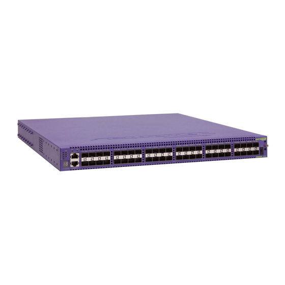
Summit Family Switches Summit X650 Series Switches The Summit X650 series switches provide 24 front-panel Ethernet ports that provide 10-gigabit Ethernet connectivity using fixed 10GBASE-T RJ-45 ports or installable SFP+ optical modules. The Summit X650 series switches include the following base models: Summit X650-24t switch (page ●... -
Page 85: Summit X650-24T Switch
Summit X650-24t Switch The front panel of the Summit X650-24t switch (Figure 69) includes: Twenty-four fixed autosensing 1000/10000 BASE-T ports (ports 1–24) that provide high-density ● copper connectivity 10/100/1000 Mbps management port ● Serial console port used to connect a terminal and perform local management ●... -
Page 86: Summit X650-24X Switch
Summit Family Switches Summit X650-24x Switch The front panel of the Summit X450-24x switch (Figure 71) includes: Twenty-four ports that can use 10GBASE-X SFP+ optical modules. (Ports 1–24 can also be populated ● with 1000BASE-X SFP modules.) For information about supported optical modules, see the latest version of the ExtremeXOS Release Notes. -
Page 87: Summit X650 Series Switch Leds
Summit X650 Series Switch LEDs Table 27 describes the LEDs on the Summit X650 series switches. Table 27: LEDs on the Summit X650 Series Switches Label or Type Color/State Meaning Front Panel LEDs MGMT Blinking Green Normal operation Blinking Amber Power-on self test (POST) failed;... - Page 88 Summit Family Switches Summit Family Switches Hardware Installation Guide...
-
Page 89: Chapter 2: Summit Power Supplies
Summit Power Supplies C H A P T E R This chapter describes Extreme Networks power supplies available for use with the Summit family switches. The Summit X460, X480, and X650 series switches have replaceable power supplies; redundant external power supplies are available for the other Summit series. - Page 90 Summit Power Supplies Table 28: Summit Switch and EPS Compatibility Switch Model Compatible EPS Model Number Summit X150 Series Switches Summit X150-24t EPS-160 External Power Module with EPS-T EPS-160: 10907 EPS-T: 10906 Summit X150-24x EPS-160 External Power Module with EPS-T EPS-160: 10907 EPS-T: 10906 Summit X150-24p...
- Page 91 Table 28: Summit Switch and EPS Compatibility (Continued) Switch Model Compatible EPS Model Number Summit X450e Series Switches Summit X450e-24p EPS-LD External Power Supply Unit 45019 EPS-500 External Power Supply Unit 10911 Summit X450e-48p EPS-600LS External Power Module with EPS-600LS: 10913 EPS C Chassis EPS-C: 10912 Summit X450e-24t...
-
Page 92: External Power Module (With Eps-T)
The external power supply is not connected. NOTE An AC power input cord is not provided; you can order an appropriate cord from Extreme Networks or from your local supplier. The power cord must meet the requirements listed in “Selecting Power Supply Cords”... -
Page 93: Eps-Ld External Power Supply Unit
The external power supply is not connected. NOTE An AC power input cord is not provided; you can order an appropriate cord from Extreme Networks or from your local supplier. The power cord must meet the requirements listed in “Selecting Power Supply Cords”... -
Page 94: External Power Supply Unit
The external power supply is not connected. NOTE An AC power input cord is not provided; you can order an appropriate cord from Extreme Networks or from your local supplier. The power cord must meet the requirements listed in “Selecting Power Supply Cords”... -
Page 95: Eps-150Dc External Power Module (With Eps-T2)
The EPS-150DC External Power Module (Model 10909) is a modular power supply for use in the EPS-T2 External Power System Tray. You can use the EPS-150DC as a redundant power supply with the following Extreme Networks switches: Summit X250e-24tDC switch ●... -
Page 96: Eps-600Ls External Power Module
NOTE An AC power input cord is not provided with the EPS-600LS power module. You can order an appropriate cord from Extreme Networks or from your local supplier. The power cord must meet the requirements listed in “Selecting Power Supply Cords” on page 311. -
Page 97: Poe Redundant Power Configurations
PoE Redundant Power Configurations The PoE capability of the Summit X450e-48p or X250e-48p varies depending on the number of external power modules in use. Table 34 summarizes the PoE power behavior for the Summit X450e-48p or X250e-48p switch based on the number of power modules in use. Table 34: External Power Modules and Corresponding PoE Behavior External Internal PSU... -
Page 98: External-To-Internal Psu Transfer
Summit Power Supplies Two or Three EPS-600LS Modules. When the Summit X450e-48p or X250e-48p switch detects that an EPS-C is connected and providing stable power from two or three EPS-600LS power modules, the PoE power budget is automatically recalculated to enable 740 W of PoE power. The internal PSU is disabled to prevent damage from excessive current demands beyond the capabilities of the internal PSU. -
Page 99: Summit X460 Power Supplies
NOTE An AC power input cord is not provided with an Summit X460 AC power supply. You can order an appropriate cord from Extreme Networks or from your local supplier. The power cord must meet the requirements listed in “Selecting Power Supply Cords” on page 311. - Page 100 Summit Power Supplies Table 36: Summit X460 300 W AC PSU LED Meanings LED Label and Color DC OK Green/red Green bicolor Meaning No AC input power Steady red No AC input power; receiving standby output from system. AC input good; 12 V output is disabled. Standby output is ON. Steady red AC input good;...
- Page 101 The Summit X460 750 W AC power supply has the status LEDs listed in Table Table 38: Summit X460 750 W AC PSU LED Meanings Label and Color State Meaning AC OK No AC input Green AC input is good. DC OK Both DC outputs (55 V and 12 V) are bad or not enabled.
-
Page 102: Summit X480 Power Supplies
An AC power input cord is not provided with the Summit X480 AC power supply. You can order an appropriate cord from Extreme Networks or from your local supplier. The power cord must meet the requirements listed in “Selecting Power Supply Cords”... -
Page 103: Summit X650 Power Supplies
An AC power input cord is not provided with the Summit X650 AC power supply. You can order an appropriate cord from Extreme Networks or from your local supplier. The power cord must meet the requirements listed in “Selecting Power Supply Cords”... - Page 104 Summit Power Supplies Summit Family Switches Hardware Installation Guide...
-
Page 105: Chapter 3: Summit Option Cards And Versatile Interface Modules
Summit Option Cards and Versatile Interface Modules C H A P T E R This chapter describes port option cards, versatile interface modules (VIMs), and stacking modules that are available for use with Summit family switches. These option cards add 10-Gbps copper or fiber I/O ports or high-performance stacking ports to the back panel of compatible switches. - Page 106 Summit Option Cards and Versatile Interface Modules Table 41: Optional Port Cards and Modules for Summit Switches Card or Module No. of Type Name Ports Type of Ports Compatible Switch Series 10-Gbps XGM-2xn XENPAK optical I/O ports Summit X450 I/O Port XGM2-2xn XENPAK optical I/O ports Summit X450a, X450e...
-
Page 107: Summit Xgm-2Xn Option Card
For current information about compatible XENPAK modules and the minimum required software, refer to the most recent version of the ExtremeXOS Release Notes. For more information about XENPAK modules, refer to the Extreme Networks Pluggable Interface Modules Installation Guide. NOTE The ExtremeXOS software also recognizes standards-based CX-4 XENPAKs;... -
Page 108: Summit Xgm2-2Xn Option Card
SH_010 For current information about compatible XENPAK modules and the minimum required software, refer to the most recent version of the ExtremeXOS Release Notes. For information about XENPAK modules, refer to the Extreme Networks Pluggable Interface Modules Installation Guide. NOTE Standards-based CX-4 XENPAKs are also recognized by ExtremeXOS;... -
Page 109: Summit Xgm2-2Xf Option Card
For current information about compatible XFP modules and the minimum required software, refer to the most recent version of the ExtremeXOS Release Notes. For more information about XFP modules, refer to the Extreme Networks Pluggable Interface Modules Installation Guide. Summit Family Switches Hardware Installation Guide... -
Page 110: Summit Xgm2-2Sf Option Card
For current information about compatible SFP+ modules and the minimum required software, refer to the most recent version of the ExtremeXOS Release Notes. For more information about SFP+ modules, refer to the Extreme Networks Pluggable Interface Modules Installation Guide. Summit XGM2-2bt Option Card The XGM2-2bt option card allows you to add two fixed 10GBASE-T ports to the following switches: Summit X350 series switch, running ExtremeXOS 12.2.1 or later... -
Page 111: Vim1 Versatile Interface Modules
VIM1 Versatile Interface Modules The back panel of the Summit X650 series switch has a replaceable VIM1 versatile interface module. These modules provide dedicated high-speed stacking ports or Ethernet ports. For more information about using the stacking ports, see Chapter VIM1-SummitStack Versatile Interface Module The VIM1-SummitStack versatile interface module (Figure... -
Page 112: Vim1-10G8X Versatile Interface Module
Summit X650 series switches. Each switch must have an installed VIM1-SummitStack512 module. To connect these ports, you must use stacking cables with compatible connectors, available from Extreme Networks. The VIM1-SummitStack512 module requires ExtremeXOS 12.3.3 software (or later) installed on the Summit X650 series switch. -
Page 113: Vim1-Summitstack256 Versatile Interface Module
(Figure 82) provides two 128-Gbps SummitStack stacking ports. To connect these ports, you must use stacking cables with compatible connectors, available from Extreme Networks. The VIM1-SummitStack256 module requires ExtremeXOS 12.4.1 software (or later) installed on the Summit X650 series switch. -
Page 114: Vim2-10G4X Versatile Interface Module
The VIM2-SummitStack128 versatile interface module (Figure 85) provides two 64-Gbps SummitStack stacking ports. To connect these ports, you must use stacking cables with compatible connectors, available from Extreme Networks. Figure 85: VIM2-SummitStack128 Versatile Interface Module Stack port 1 LEDs Stack port 2... -
Page 115: Optional Ports For The Summit X460 Series Switches
For current information about compatible SFP+ modules and the minimum required software, refer to the most recent version of the ExtremeXOS Release Notes. For more information about SFP+ modules, refer to the Extreme Networks Pluggable Interfaces Hardware Installation Guide. Figure 86: XGM3-2sf Option Card... - Page 116 Summit Option Cards and Versatile Interface Modules Summit Family Switches Hardware Installation Guide...
-
Page 117: Part 2: Installing The Hardware
Installing the Hardware P A R T... -
Page 119: Chapter 4: Site Preparation
Site Preparation C H A P T E R This chapter includes the following sections: Planning Your Site on page 120 ● Meeting Site Requirements on page 120 ● Evaluating and Meeting Cable Requirements on page 125 ● Meeting Power Requirements on page 130 ●... -
Page 120: Planning Your Site
● After examining your physical site and verifying that all environment requirements are met, evaluate and compare your existing cable plant with the requirements of the Extreme Networks equipment to determine if you need to install new cables. Meeting power requirements ●... -
Page 121: Wiring Closet Considerations
The organizations listed in Table 45 are authorities on electrical codes. Table 45: Authorities on Electrical Codes Organization Address Web Site URL National Electrical Code (NEC) Classification (USA only) NFPA http://www.nfpa.org 1 Batterymarch Park Recognized authority on safe electrical wiring. Federal, Quincy, Massachusetts state, and local governments use NEC standards to 02169... -
Page 122: Temperature
Spacing Requirements and Airflow Be sure that cables and other equipment do not block the air intake or outflow on an Extreme Networks switch. It is best to have at least 3 inches (8 cm) of clear space in front of the air intake and outflow vents on the sides of the switch;... -
Page 123: Electrostatic Discharge
This will ensure good grounding between the chassis, rack, and earth ground. NOTE Because building codes vary worldwide, Extreme Networks strongly recommends that you consult an electrical contractor to ensure proper equipment grounding for your specific installation. Summit Family Switches Hardware Installation Guide... -
Page 124: Space Requirements For The Rack
WARNING! Extreme Networks switches do not have a switch for turning power to the unit on and off. For systems using an AC power supply, power to the switch is disconnected by removing the wall plug from the electrical outlet. -
Page 125: Evaluating And Meeting Cable Requirements
Assign a unique block of sequential numbers to the group of cables that run between each pair of ● wiring closets. Assign a unique identification number to each equipment rack. ● Identify all wiring closets by labeling the front panel of your Extreme Networks equipment and ● other hardware. Keep accurate and current cable identification records. ●... -
Page 126: Installing Cable
Site Preparation Installing Cable When you connect cable to your network equipment: Examine cable for cuts, bends, and nicks. ● Support cable using a cable manager that is mounted above connectors to avoid unnecessary weight ● on the cable bundles. Use cable managers to route cable bundles to the left and right of the network equipment to ●... -
Page 127: Fiber Optic Cable
It is also important not to stretch the cable during installation. Extreme Networks recommends that the bend radius for fiber optic cable equal 2 inches (5.08 cm) minimum for each 90-degree turn as shown in Figure 90 on page 128. -
Page 128: Cable Distances
– 10BASE-T Category 3 and higher UTP cable – Proprietary to Extreme Networks. Connections between two Extreme Networks 1000BASE-LX interfaces that use 10/125 µm single-mode fiber can use a maximum distance of 10,000 meters. Summit Family Switches Hardware Installation Guide... -
Page 129: Rj-45 Connector Jackets
RJ-45 Connector Jackets Use RJ-45 cable with connector jackets that are flush with the connector or that have connectors with a no-snag feature. Using cable with jackets that are wider than the connectors can cause: Connectors that are not properly aligned with the port. ●... -
Page 130: Meeting Power Requirements
AC power input cords are not provided with Summit switches and power supplies. You can purchase AC power cords for use in the US and Canada from Extreme Networks or from your local supplier. Power supply cords for use outside of the United States and Canada are typically provided separately by third-party distribution centers. -
Page 131: Uninterruptible Power Supply Requirements
132) NOTE Extreme Networks recommends that you use a UPS that provides online protection. Calculating Volt-Amperage Requirements To determine the size of UPS that you need: 1 Locate the voltage and amperage requirements for each piece of equipment. These numbers are usually located on a sticker on the back or bottom of your equipment. -
Page 132: Ups Transition Time
UPS Transition Time Transition time is the time that is necessary for the UPS to transfer from utility power to full-load battery power. For Extreme Networks products, a transition time of less than 20 milliseconds is required for optimum performance. -
Page 133: Chapter 5: Building A Summitstack Configuration
Building a SummitStack Configuration C H A P T E R This chapter provides information about how to build and connect a SummitStack configuration. If you intend to use the SummitStack feature, read this chapter before installing the set of Summit family switches that will be included in the SummitStack configuration. -
Page 134: Slot Numbers
Building a SummitStack Configuration Figure 92: Summit Switches Connected in a SummitStack Configuration Stack Port 1 Stack Port 2 SummitStack cables Summit switches Stack Port 1 Stack Port 2 Stack Port 1 Stack Port 2 Stack Port 1 Stack Port 2 SH_176 The stack operates as a single switch with a single IP address and a single point of authentication. -
Page 135: About Redundancy
For example, in a stack that combines Summit X480 series switches with Summit X650 series switches, Extreme Networks recommends assigning the master/backup roles to two Summit X480 series switches. In a stack with multiple master-capable switches, it is possible for more than one switch to try become the stack master if the stack is physically severed. -
Page 136: Stacking Cables
40 Gbps, 256 Gbps, or 512 Gbps full duplex bandwidth. Stacking connections using the native stacking ports require stacking cables that are specific to the type of stacking port. These cables are available from Extreme Networks in lengths from 0.5 meter to 100 meters. Table 48 lists the cable types and compatible Summit switches or modules. -
Page 137: Choosing Between Native And Alternate Stacking Ports
QSFP+ active optical cable, 100 meters NOTE: Additional types of stacking cables may have been released since this guide was published. Contact your Extreme Networks sales representative for the most recent information about available cables. Choosing Between Native and Alternate Stacking Ports The dedicated stacking ports (either fixed or on installed VIMs or stacking modules) are called native stacking ports. -
Page 138: Placing Summit Family Switches For Stacked Operation
Ethernet management port on each switch. Because of the weight of the cable, Extreme Networks strongly recommends the use of cable ● management hardware to support the cables and provide strain relief at the connectors when you use the SummitStack 128G cable, SummitStack 64G cable, or SummitStack 128G/64G cable. -
Page 139: Combining Switches From Different Series
Combining Switches from Different Series Switches from some Summit series have more memory than other Summit models and support additional features. If the stack combines switches from different Summit series, refer to Table 47 on page 135 and follow these additional guidelines: To support the additional capabilities in a stack that includes multiple Summit switch series, the ●... - Page 140 Building a SummitStack Configuration Table 49: Alternate Stacking Ports Alternate Stacking Alternate Stacking Location of Alternate Switch Model Port 1 Port 2 Stacking Ports Summit X450a-24t XGM2-2xf option card Summit X450a-24tDC XGM2-2xn option card Summit X450a-24x XGM2-2sf option card Summit X450a-24xDC XGM2-2bt option card Summit X450a-24p Summit X450e-24t...
-
Page 141: Connecting The Switches To Form The Stack Ring
Connecting the Switches to Form the Stack Ring After you have installed the individual Summit switches (see Chapter 6), connect the switches together using the stacking cables. The examples in this section show cable connections and the recommended order for connecting ports to facilitate the easy setup configuration. In general, it is best to connect Stack Port 2 on one switch to Stack Port 1 on the switch with the next higher slot number. - Page 142 Building a SummitStack Configuration Table 50 lists the recommended order for connecting the stacking ports in this example. Table 50: Recommended Order for Stacking Connections (4-Switch Stack) Connect this slot and port ..To this slot and port Slot 1 Stack Port 2 Slot 2...
- Page 143 Table 51: Recommended Order for Stacking Connections (8-Switch Stack) Connect this slot and port ..To this slot and port Slot 1 Stack Port 2 Slot 2 Stack Port 1 Slot 2 Stack Port 2 Slot 3 Stack Port 1 Slot 3...
-
Page 144: Multiple-Rack Stacking Configurations
Building a SummitStack Configuration Figure 97: SummitStack Configuration Using Summit X650 and X460 Series Switches and SummitStack 40G Cables Slot 1 Slot 2 Slot 3 Slot 4 SH_223 Multiple-Rack Stacking Configurations Figure 98 shows two Summit X480 series switches and two Summit X650 series switches physically located in two adjacent racks. - Page 145 Table 52: Recommended Order for Stacking Connections (4-Switch Stack in Two Adjacent Racks) Connect this slot and port ..To this slot and port Slot 1 Stack Port 2 Slot 2 Stack Port 1 Slot 2 Stack Port 2 Slot 3 Stack Port 1...
-
Page 146: Combining Different Types Of Stacking Ports
Building a SummitStack Configuration Combining Different Types of Stacking Ports Using special conversion cables, you can build a SummitStack configuration that combines 40-Gbps stacking connections with 256-Gbps connections or with 128-Gbps connections. Figure 100 shows a sample configuration using the following switches: Summit X650 series switches with installed VIM1-SummitStack256 modules ●... - Page 147 Figure 101 shows a similar stack configuration using the following switches: Summit X650 series switches with installed VIM1-SummitStack256 modules ● Summit X460 series switches with installed SummitStack stacking modules ● Summit X450a series switch with integrated stacking ports ● Figure 101: Combining Stack Port Types—B Summit X650 series switch Slot 1 Slot 2...
-
Page 148: Using The Summitstack-V80 Stacking Module
Building a SummitStack Configuration Using the SummitStack-V80 Stacking Module The SummitStack-V80 stacking module allows you to use active or passive direct-attach QSFP+ cables to connect stack members across rows in a data center. In Figure 102, passive copper cables are used to connect adjacent switches in the same rack, and the active fiber cables provide connections up to 100 meters long between racks. -
Page 149: Using The Vim1-Summitstack512 Module
Using the VIM1-SummitStack512 Module The VIM1-SummitStack512 versatile interface module allows you to connect two Summit X650 series switches in a cross-over or back-to-back configuration, using SummitStack 128G cables (Figure 103). This configuration provides two bidirectional links operating at 256 Gbps between the two switches. Figure 103: Stacking Connections Using VIM1-SummitStack512 Modules and SummitStack 128G Cables SH_141... -
Page 150: Using The Summitstack-V Feature
Building a SummitStack Configuration Using the SummitStack-V Feature Figure 104 shows an example of a stacking configuration that combines native and alternate stacking ports to form a stack of seven switches. The Summit X650 series switches in slots 1 and 2 are connected through their native stacking ports on installed VIM1-SummitStack256 modules, using SummitStack128 stacking cables. -
Page 151: Connecting Stacking Cables
Connecting Stacking Cables To connect Summit switches in a SummitStack configuration, use the appropriate stacking cables for the specific stacking ports on the switches. This section provides instructions to connect the following stacking cables: SummitStack 40G cable (see page 151) ●... -
Page 152: Connecting A Summitstack 128G Cable
SummitStack 128G cables are used to connect the 128-Gbps stacking ports on the VIM1-SummitStack256 and VIM1-SummitStack512 modules in Summit X650 series switches. Because of the weight of the SummitStack 128G cable, Extreme Networks strongly recommends the use of cable management hardware to support the cables and provide strain relief at the connectors. -
Page 153: Port Covers On The Vim1-Summitstack512 Module
Port Covers on the VIM1-SummitStack512 Module On the VIM1-SummitStack512 module, EMI-protective covers are installed over the port connectors. Before connecting the stacking cables, remove the connector covers from the ports that will be used. To remove a connector cover: 1 On the side of the connector nearest to the inserter/ejector lever, find the notch between the two end tabs on the cover (see Figure 108). -
Page 154: Connecting The Cable
Building a SummitStack Configuration Connecting the Cable To connect a SummitStack 128G cable: 1 Holding the cable connector with the release tab on top, align the connector with the stacking port on the VIM1 module in the Summit X650 series switch (Figure 109). - Page 155 Figure 110: Connecting the 128G Connector SH_149 b Firmly press the cable connector into the stacking port until the spring latch on top of the connector clicks into place. 2 Connect the 20G connector as follows: a Align the cable connector with the stacking port connector on the back of the switch (Figure 111).
-
Page 156: Connecting A Summitstack 128G/64G Stacking Cable
VIM1-SummitStack256 modules; the 64-Gbps stacking ports are on VIM2-SummitStack128 modules. Because of the weight of the SummitStack 128G/64G cable, Extreme Networks strongly recommends the use of cable management hardware to support the cables and provide strain relief at the connectors. - Page 157 At the Summit X650 series switch, connect the 128G connector to the VIM1-SummitStack256 module. At the Summit X480 series switch, connect the 64G connector to the VIM2-SummitStack128 module. The connection process is the same for each connector and the compatible VIM model. To connect a 128G or 64G connector: 1 Holding the cable connector with the release tab on top, align the connector with the stacking port on the VIM1...
-
Page 158: Connecting A Summitstack 64G Stacking Cable
SummitStack 64G cables are used to connect the 64-Gbps stacking ports on the VIM2-SummitStack128 module in Summit X480 series switches. Because of the weight of the SummitStack 64G cable, Extreme Networks strongly recommends the use of cable management hardware to support the cables and provide strain relief at the connectors. -
Page 159: Connecting A Summitstack 64G/20G Stacking Cable
To connect a SummitStack 64G cable: 1 Holding the cable connector with the release tab on top, align the connector with the stacking port on the VIM2 module in the Summit X480 series switch (Figure 117). Figure 117: Connecting a SummitStack 64G Cable SH_164 2 Firmly press the cable connector into the stacking port until the spring latch on top of the connector clicks into place. - Page 160 Building a SummitStack Configuration To connect a SummitStack 64G/20G cable: 1 Connect the 64-Gbps connector to the VIM2 module as follows: a Holding the cable connector with the release tab on top, align the connector with the stacking port on the VIM2 module in the Summit X480 series switch (Figure 118).
-
Page 161: Connecting Active Or Passive Qsfp+ Cables
Connecting Active or Passive QSFP+ Cables The QSFP+ direct-attach cable is used to connect ports on SummitStack-V80 stacking modules installed in Summit X460 series switches. To connect a QSFP+ direct-attach cable: 1 Holding the QSFP+ connector by its sides, insert the connector into the port on the switch (Figure 120). -
Page 162: Management Port Cabling
Building a SummitStack Configuration Management Port Cabling Connect the master, backup, and all other master-capable switches to your management network using the Ethernet management port on the rear panel of each switch. If you choose the default redundancy setup, only slots 1 and 2 are allowed to become master. You may connect all switch management ports in the stack if you choose to do so. -
Page 163: Chapter 6: Installing Summit Family Switches
Installing Summit Family Switches C H A P T E R This chapter describes how to install Summit family switches and associated components. The chapter also includes information about connecting network interface cables and establishing management access. If you intend to use the SummitStack feature, see Chapter 5 before you install the switches. -
Page 164: Safety Information
Installing Summit Family Switches Safety Information Read the information in this chapter thoroughly before you attempt to install or remove a Summit switch. NOTE Appendix A, “Safety Information” for additional safety information and Appendix B, “Technical Specifications” for additional information regarding regulatory compliance certifications. CAUTION Be sure that proper ESD controls are in use before switch maintenance is performed. -
Page 165: Rack-Mounting A Summit Switch (Models Other Than Summit X460, X480, And X650 Series)
A Summit family switch can be mounted in a standard 19-inch (48.26 cm) rack or placed free-standing on a tabletop. The installation process includes the following tasks: 1 Install the switch in a rack or on a table. 2 (Optional) Install port option cards. 3 Ground the switch (DC-powered units only). -
Page 166: Free-Standing And Desktop Mounting Of Multiple Switches
Installing Summit Family Switches To rack-mount a Summit switch: 1 Place the switch upright on a stable work surface. 2 Place a mounting bracket over the mounting holes on one side of the unit. 3 Insert the screws and fully tighten with a suitable screwdriver, as shown in Figure 121. -
Page 167: Installing Summit Dc-Powered Switches
Installing Summit DC-Powered Switches This section provides additional details about installing the following Summit DC-powered switches: Summit X250e-24tDC ● Summit X250e-24xDC ● Summit X250e-48tDC ● Summit X450a-24tDC ● Summit X450a-24xDC ● Summit X450a-48tDC ● You must adhere to specific safety requirements when you connect o a DC power source for one of these Summit switches. - Page 168 Installing Summit Family Switches WARNING! Be sure to connect the chassis ground wire before you connect any power cables. To ground the switch: 1 At one end of the wire, strip the insulation to expose 1/2 inch (12 mm) of bare wire. 2 Identify the grounding lug on the back of the switch.
-
Page 169: Connecting The Dc Wiring Harness To The Dc Source Voltage
Figure 124: Attaching the Ground Wire to a Summit X250e Series Switch SH_067_ground_X250e 4 Using a straight-tip torque screwdriver, tighten the retaining screw to 20 pound-inches (2.25 Newton-meters). 5 Connect the other end of the wire to a known reliable earth ground point at your site. Connecting the DC Wiring Harness to the DC Source Voltage After the internal DC power supply is installed, it must be connected to a DC power source. -
Page 170: Attaching The Dc Wiring Harness To The Dc Power Socket On The Switch
Installing Summit Family Switches Figure 125: Three-wire Cable Harness EWUG005 NOTE Each wire on the harness has been properly marked for proper attachment to the DC power source. Leave these labels on each lead wire for future reference. Attaching the DC Wiring Harness to the DC Power Socket on the Switch After the DC wiring harness is connected to a permanent DC voltage source by a qualified, licensed electrician, you can remove, replace, and maintain the Summit DC-powered switch without further electrician assistance. - Page 171 Figure 126: DC Power Socket on a Summit X250e Series DC-Powered Switch Redundant Power Input -48 V 1 .5 A Ma x ! See Manual DC power socket SH_068_DC_connector NOTE Figure 126 shows the rear panel of a Summit X250e series DC-powered switch. The rear panel of other Summit DC-powered switches may vary slightly;...
-
Page 172: Installing A Summit X460 Series Switch
Installing Summit Family Switches Installing a Summit X460 Series Switch The Summit X460 series switch fits into a standard 19-inch equipment rack. The provided rack-mounting brackets attach to the front of the switch unit and are adaptable to either a front-mount or mid-mount installation. -
Page 173: Mid-Mounting A Switch In A Two-Post Rack
Mid-Mounting a Switch in a Two-Post Rack To mid-mount a Summit X460 series switch in a two-post rack: 1 Attach an ESD-preventive wrist strap to your bare wrist and connect the metal end to an appropriate ground point on the rack. 2 On one side of the switch, set the bracket against the switch housing, with the flange toward the back of the switch (see Figure... -
Page 174: Front-Mounting A Switch In A Two-Post Rack
Installing Summit Family Switches 6 Secure the mounting bracket flanges to the rack, using screws that are appropriate for the rack. (Rack-mounting screws are not provided.) The Summit X460 series switch is shipped without installed power supplies. You can install one or two power supplies. -
Page 175: Installing Summit X460 Ac Power Supplies
AC Power Supply Cords An AC power cord is not included with Summit X460 AC PSUs. AC power cords for use in the US and Canada from Extreme Networks or from your local supplier. The cord must meet the requirements listed under “Selecting Power Supply Cords”... -
Page 176: Installing A Summit X460 300 W Ac Psu
Installing Summit Family Switches Installing a Summit X460 300 W AC PSU WARNING! To prevent an electrical hazard, make sure that the AC power cord is not connected to the PSU before you install the PSU in the power supply bay. CAUTION Make sure that the AC PSU circuit is not overloaded. - Page 177 Figure 132: Installing a PSU SH_202 NOTE If PSUs are not installed in both power supply bays, be sure to install a cover over the unoccupied bay. Unoccupied bays must always be covered to maintain proper system ventilation and EMI levels. 4 Connect the AC power cord to the input connector on the PSU and rotate the wire clip into place over the power cord connector.
-
Page 178: Installing A Summit X460 750 W Ac Psu
Installing Summit Family Switches Installing a Summit X460 750 W AC PSU WARNING! To prevent an electrical hazard, make sure that the AC power cord is not connected to the PSU before you install the PSU in the power supply bay. CAUTION Make sure that the AC PSU circuit is not overloaded. - Page 179 Figure 134: Installing a 750 W AC PSU SH_205 NOTE If PSUs are not installed in both power supply bays, be sure to install a cover over the unoccupied bay. Unoccupied bays must always be covered to maintain proper system ventilation and EMI levels. 4 Connect the AC power cord as follows: a If necessary, slide the plastic cord retainer farther away from the back of the switch (Figure...
- Page 180 Installing Summit Family Switches Figure 136: Connecting the Power Cord SH_228 c Open the clip and slip it over the barrel of the connector (Figure 137). Figure 137: Attaching the Power Cord Retainer SH_229 d Snap the clip firmly around the connector. 5 Connect the other end of the power cord to an AC power outlet.
-
Page 181: Installing A Summit X460 Dc Power Supply
Installing a Summit X460 DC Power Supply CAUTION Make sure that the Summit X460 DC PSU circuit is not overloaded. Use proper over-current protection, such as a circuit-breaker, to prevent over-current conditions. You may use up to a 30-Amp breaker. To install the Summit X460 DC PSU, perform the following tasks in the order listed: 1 Prepare the power cables and ground cable by attaching the provided connection lugs to the cables (see... -
Page 182: Preparing The Cables
Installing Summit Family Switches Preparing the Cables A ring terminal and two spade terminals are provided with the PSU. You need a crimping tool to attach the terminals to the power and ground cables. To prepare the cables: 1 On each wire, strip 0.25 inch of insulation from one end. 2 Insert the stripped wire end all the way into the barrel of the terminal (Figure 138) and crimp the... -
Page 183: Connecting The Ground Cable
3 Verify that the PSU is right side up (see Figure 140). 4 Carefully slide the PSU all the way into the power supply bay (see Figure 140). Push the PSU in until the latch snaps into place. CAUTION Do not slam the PSU into the switch. Figure 140: Installing a Summit X460 DC PSU SH_208 To install a second PSU, repeat steps 2 through 4. -
Page 184: Connecting The Psu To The Dc Source Voltage
Installing Summit Family Switches Figure 141: Connecting the Ground Wire SH_209 1 = Grounding point 2 = Ground wire Connecting the PSU to the DC Source Voltage The DC power connection at your facility must be made by a qualified electrician, following the instructions in this section. - Page 185 Figure 142: Connecting the DC Power Cables (Part 1) -48V (–) SH_210 d Tighten both screws on the terminal block to 11 inch-pounds (1.25 Newton-meters) (Figure 143). Summit Family Switches Hardware Installation Guide...
- Page 186 Installing Summit Family Switches 5 Slide the cover into place over the terminal block (Figure 143). Figure 143: Connecting the DC Power Cables (Part 2) -48V (–) SH_211 6 Connect the cables to the DC source voltage, using hardware appropriate to the installation site and following local and national electrical codes.
-
Page 187: Installing A Summit X480 Series Switch
Installing a Summit X480 Series Switch The Summit X480 series switch fits into a standard 19-inch equipment rack. The provided rack-mounting brackets are adaptable to either two-post or four-post mounting. The installation process includes the following tasks: 1 Install the switch in the rack. 2 (Optional) Install a VIM2 versatile interface module. -
Page 188: Selecting Rear Mounting Brackets
Installing Summit Family Switches Selecting Rear Mounting Brackets The Summit X480 series switch has two sets of rear mounting brackets. Use the bracket that best suits the type of rack installation: Shorter brackets—mid-mounting in a 2-post rack ● Longer brackets—mounting in a 4-post rack ●... - Page 189 3 From the back of the equipment rack, slide the switch into place over the mounting brackets (see Figure 145). Make sure the brackets slide between the support pegs on both sides of the switch. Figure 145: Sliding the Switch onto the Rear Mounting Brackets SH_126 4 Push the switch forward as far as it will go, until the bracket support pegs are against the T of the mounting bracket...
- Page 190 Installing Summit Family Switches 5 At the front of the switch, place a front mounting bracket against each side of the switch, in front of the ventilation openings in the side of the switch (Figure 147) Figure 147: Positioning the Front Mounting Brackets SH_129 6 Using the provided screws, attach each front bracket to the switch (Figure...
-
Page 191: Front-Mounting The Switch In A Two-Post Rack
Front-Mounting the Switch in a Two-Post Rack To front-mount the switch in a two-post rack: 1 Place the switch upright on a secure work surface. 2 Place a front mounting bracket over the mounting holes on one side of the unit, with the flange at the front of the switch (Figure 149). -
Page 192: Installing The Switch In A Four-Post Rack
Installing Summit Family Switches Installing the Switch in a Four-Post Rack To install the switch in a four-post rack: 1 At the back of the rack, attach a rear mounting bracket to each rear post, as shown in Figure 151. Figure 151: Attaching Rear Mounting Brackets—Four-Post Installation SH_145 2 Attach an ESD-preventive wrist strap to your wrist and connect the metal end to an appropriate... - Page 193 5 From the front of the rack, slide the switch onto the rear mounting brackets (Figure 153). Figure 153: Installing the Switch—Four-Post Installation SH_146 6 Slide the switch all the way into the rack and secure the mounting brackets to the front posts using suitable screws (Figure 154).
-
Page 194: Installing Summit X480 Power Supplies
AC Power Supply Cords An AC power cord is not included with the Summit X480 AC PSU. AC power cords for use in the US and Canada from Extreme Networks or from your local supplier. The cord must meet the following requirements: The power cord must be agency-certified for the country of use and rated for 100-240 V AC. - Page 195 3 Verify that the PSU is right side up, with the latching tab at the left of the unit (see Figure 156). 4 Carefully slide the PSU all the way into the power supply bay (see Figure 156). Push the PSU in until the latch snaps into place.
-
Page 196: Installing A Summit X480 Dc Power Supply
Installing Summit Family Switches Installing a Summit X480 DC Power Supply To install the Summit X480 DC PSU, perform the following tasks in the order listed: 1 Prepare the power cables and ground cable by attaching the provided connection lugs to the cables (see next section). -
Page 197: Preparing The Cables
Preparing the Cables Three spade-type terminals are provided with the PSU. You need a crimping tool to attach the terminals to the power and ground cables. To prepare the cables: 1 On each wire, strip 0.25 inch of insulation from one end. 2 Insert the stripped wire end all the way into the barrel of the terminal (Figure 157) and crimp the... -
Page 198: Connecting The Ground Wire
Installing Summit Family Switches CAUTION Do not slam the PSU into the switch. Figure 159: Installing a DC PSU SH_158 5 To install a second PSU, repeat steps 2 through 4. Connecting the Ground Wire WARNING! Be sure to connect the chassis ground wire before you connect any power cables. Be sure to disconnect the ground wire after you disconnect all power cables. - Page 199 4 Identify the grounding point at the left of the terminal block (Figure 160). Figure 160: Connecting the Ground Wire SH_159 Summit Family Switches Hardware Installation Guide...
-
Page 200: Connecting The Psu To The Dc Source Voltage
Installing Summit Family Switches 5 Connect the ground wire to the grounding point as follows: a Loosen the screw enough to allow the spade terminal to slide underneath the captive square washer (Figure 161). b Slide the spade terminal of the ground wire under the captive square washer. c Tighten the screw to 7 inch-pounds (0.99 Newton meters) (Figure 161). - Page 201 To connect the DC power input cables: 1 Verify that the DC circuit is de-energized. 2 Connect the DC power input cables as follows: a On each terminal, loosen the screw enough to allow the spade terminal to slide underneath the captive square washer (Figure 162).
- Page 202 Installing Summit Family Switches d Tighten both screws on the terminal block to 7 inch-pounds (0.99 Newton meters) (Figure 163). 3 Snap the cover into place over the terminal block (Figure 163). Figure 163: Connecting the DC Power Cables (Part 2) (–) -48V SH_162...
-
Page 203: Installing A Summit X650 Series Switch
Installing a Summit X650 Series Switch The Summit X650 series switch fits into a standard 19-inch equipment rack. The provided rack-mounting brackets are adaptable to either two-post or four-post (cabinet) mounting. The installation process includes the following tasks: 1 Install the switch in the rack. 2 Install one or two power supplies and connect power cables. -
Page 204: Selecting Rear Mounting Brackets
Installing Summit Family Switches Selecting Rear Mounting Brackets To allow installation of the switch in cabinets of different depths, the Summit X650 series switch has two sets of rear mounting brackets. Use the bracket that best suits the cabinet depth or rack depth where the switch will be installed: Shorter brackets—cabinets or racks 25 inches to 31 inches (63.5 cm to 76.7 cm) deep ●... - Page 205 Figure 165: Sliding the Switch onto the Rear Mounting Brackets SH_082 4 Push the switch forward as far as it will go, until the bracket support pegs are against the T of the mounting bracket (Figure 166). Securely tighten the rack mounting screws. Figure 166: Fastening the Rear Mounting Brackets—Two-Post Rack SH_098 Summit Family Switches Hardware Installation Guide...
- Page 206 Installing Summit Family Switches 5 At the front of the switch, place a front mounting bracket against each side of the switch, in front of the ventilation openings in the side of the switch (Figure 167) Make sure there is space between the bracket and the ventilation openings. Figure 167: Positioning the Front Mounting Brackets—Two-Post Rack SH_099 6 Using the provided screws, attach each front bracket to the switch...
-
Page 207: Installing The Switch In A Cabinet Or Four-Post Rack
Installing the Switch in a Cabinet or Four-Post Rack To install the switch in a cabinet or four-post rack: 1 At the back of the cabinet, attach a rear mounting bracket to each rear post, as shown in Figure 169 Figure 169: Attaching Rear Mounting Brackets—Cabinet Installation SH_102 2 Attach an ESD-preventive wrist strap to your wrist and connect the metal end to an appropriate... - Page 208 Installing Summit Family Switches 5 From the front of the cabinet, slide the switch onto the rear mounting brackets (Figure 171). Figure 171: Installing the Switch—Cabinet Installation SH_080 6 Slide the switch all the way into the cabinet and secure the mounting brackets to the front rack posts using suitable screws (Figure 172).
-
Page 209: Installing Summit X650 Power Supplies
AC Power Supply Cords An AC power cord is not included with the Summit X650 AC PSU. AC power cords for use in the US and Canada from Extreme Networks or from your local supplier. The cord must meet the following requirements: The power cord must be agency-certified for the country of use and rated for 100-240 V AC. - Page 210 Installing Summit Family Switches 3 Verify that the PSU is right side up, with the latching tab at the right of the unit (see Figure 174). 4 Carefully slide the PSU all the way into the power supply bay (see Figure 174).
-
Page 211: Installing A Summit X650 Dc Power Supply
Installing a Summit X650 DC Power Supply CAUTION Make sure that the Summit X650 DC PSU circuit is not overloaded. Use proper over-current protection, such as a circuit-breaker, to prevent over-current conditions. You may use up to a 30-Amp breaker. To install the Summit X650 DC PSU, perform the following tasks in the order listed: 1 Prepare the power cables and ground cable by attaching the provided connection lugs to the cables (see next section). -
Page 212: Preparing The Cables
Installing Summit Family Switches Preparing the Cables A ring terminal and two spade terminals are provided with the PSU. You need a crimping tool to attach the terminals to the power and ground cables. To prepare the cables: 1 On each wire, strip 0.25 inch of insulation from one end. 2 Insert the stripped wire end all the way into the barrel of the terminal (Figure 175) and crimp the... - Page 213 2 Verify that the PSU is right side up (see Figure 177). 3 Carefully slide the PSU all the way into the power supply bay (see Figure 177). Push the PSU in until the latch snaps into place. CAUTION Do not slam the PSU into the switch. Figure 177: Installing a Summit X650 DC PSU SH_107 4 To install more PSUs, repeat steps...
-
Page 214: Connecting The Ground Cable
Installing Summit Family Switches Connecting the Ground Cable WARNING! Be sure to connect the chassis ground wire before you connect any power cables. Be sure to disconnect the ground wire after you disconnect all power cables. To connect the ground wire: 1 Verify that the DC circuit is de-energized. - Page 215 To connect the DC power input cables: 1 Verify that the DC circuit is de-energized. 2 Slide the cover off the terminal block (Figure 179). 3 Connect the DC power input cables as follows: a On each terminal, loosen the screw enough to allow the spade terminal to slide underneath the captive square washer.
-
Page 216: Connecting Network Interface Cables
Installing Summit Family Switches 4 Slide the cover into place over the terminal block (Figure 180). Figure 180: Connecting the DC Power Cables (Part 2) -48V (–) SH_112 5 Connect the cables to the DC source voltage, using hardware appropriate to the installation site and following local and national electrical codes. -
Page 217: Initial Management Access
● Flow control—XON/XOFF ● The terminal or PC with terminal-emulation software that you connect to an Extreme Networks switch must be configured with these settings. This procedure is described in the documentation supplied with the terminal. Appropriate cables are available from your local supplier, or you can make your own. To ensure the electromagnetic compatibility of the unit, use only shielded serial cables. - Page 218 Installing Summit Family Switches To manually configure the IP settings: 1 Connect a terminal or PC with terminal-emulation software to the console port on the Summit switch. 2 At the terminal, press [Return] one or more times until you see the login prompt. 3 At the login prompt, enter the default user name admin to log on with administrator privileges.
-
Page 219: Chapter 7: Installing Summit External Power Supplies
Safety Only trained service personnel should perform service to Extreme Networks switches and their components. Trained service personnel have read all related installation manuals, have the technical training and experience necessary to be aware of the hazards to which they are exposed in performing a task, and are aware of measures to minimize the danger to themselves or other persons. -
Page 220: Pre-Installation Requirements
WARNING! Extreme Networks AC PSUs do not have switches for turning the unit on and off. Remove the wall plug from the electrical outlet to disconnect the power to an Extreme Networks AC PSU. Make sure that this connection is easily accessible. -
Page 221: Installing An Eps-160 External Power Module (With Eps-T)
You can order the EPS-T chassis with one or two EPS-160 power supplies already installed. You can also order an additional power supply from your Extreme Networks reseller. The EPS-T can be mounted in a rack or placed free-standing on a tabletop. -
Page 222: Connecting The Eps-160 Power Supply To The Switch
Installing Summit External Power Supplies Connecting the EPS-160 Power Supply to the Switch One end of the EPS-160 redundant power cord has a keyed connector to ensure correct alignment of the connector (Figure 182). The key is a plastic tab on the cord connector housing that fits into the EPS-160 unit. - Page 223 Figure 183: Redundant Power Connections Slot for plug To AC Keyed end of redundant power cable Redundant power cable S450_008 3 Connect an appropriate AC power cord to the AC connector on each unit. NOTE An AC power cord is not provided with the EPS-160 unit. See “Selecting Power Supply Cords”...
-
Page 224: Installing An Eps-Ld External Power Supply
EPS-LD facing either the front or the back of the rack. For this reason, each unit has two sets of mounting holes on each side. Extreme Networks recommends that you position the EPS-LD so that the power output connectors on the EPS-LD unit are on the same side as the external connector on the connecting switch. -
Page 225: Connecting The Eps-Ld To The Switch
4 Slide the EPS-LD into a 19-inch rack and secure it using appropriate rack-mount screws. NOTE Extreme Networks recommends that you position the EPS-LD so that the output connectors are on the same side as the external connector on the connecting switch. If you mount the EPS-LD with the connectors facing in the opposite direction from the Summit switch connector, leave at least 1 U between the switch and the EPS-LD through which to slide the power cords. -
Page 226: Connecting The Eps-Ld To Power
Installing Summit External Power Supplies Figure 186: Connecting an EPS-LD Unit to a Switch Keyed end of Slot for key redundant power cable EPS-LD To AC Extreme switch Redundant power cable To AC Collin's ES4K021A XM_053 Connecting the EPS-LD to Power An AC input power cord is not provided with the EPS-LD. -
Page 227: Installing An Eps-500 External Power Supply Unit
You can position the EPS-500 facing either the front or the back of the rack. For this reason, each unit has two sets of mounting holes on each side. Extreme Networks recommends that you position the EPS-500 unit so that the power output connectors of the EPS-500 unit are on the same side as the external connector on the connecting switch. -
Page 228: Connecting The Eps-500 Power Supply
Installing Summit External Power Supplies NOTE Extreme Networks recommends that you position the EPS-500 so that the output connectors are on the same side as the external connector on the connecting switch. If you position the EPS-500 with the connectors facing in the opposite direction from the Summit switch connector, leave at least 1 U between the switch and the EPS-500 through which to slide the power cords. - Page 229 Figure 189: Connecting an EPS-500 Unit to a Switch Keyed end of redundant power cord Slot for key EPS-500 To AC Extreme switch Redundant power cord To AC Collin's ES4K021A XM_074 3 Connect an appropriate AC input power cord to the AC connector on the EPS-500 unit. NOTE An AC power cord is not provided with the EPS-500 unit.
-
Page 230: Installing An Eps-150Dc External Power Module (With Eps-T2)
The EPS-150DC power supply is a modular power supply for use in the EPS-T2 External Power System Tray. The EPS-T2 is a rack-mountable chassis or tray that holds one or two EPS-150DC power supplies. Each EPS-150DC provides one-to-one redundancy to an attached Extreme Networks switch. You must install the EPS-150DC power supply in the EPS-T2 tray. -
Page 231: Installing An Eps-150Dc Power Supply
Installing an EPS-150DC Power Supply NOTE Install the EPS-T2 before you begin installing the EPS-150DC. WARNING! Always be sure that the DC circuit is de-energized before connecting or disconnecting the DC wiring harness at the DC power socket on the rear of the EPS-150DC unit, and before connecting or disconnecting the redundant power cord between the switch and the EPS-150DC unit. -
Page 232: Installing An Eps-150Dc Unit Into An Eps-T2
Installing Summit External Power Supplies Figure 191: Three-wire Cable Harness EWUG005 NOTE Each wire on the harness has been properly marked for proper attachment to the DC power source. Leave these labels on each lead wire for future reference. Installing an EPS-150DC Unit into an EPS-T2 WARNING! The EPS-150DC unit and rack must be connected to protective earth ground. -
Page 233: Connecting The Eps-150Dc To A Switch
Figure 192: Connecting the Input Cable to the EPS-150DC Unit EPS-150DC DC wiring in EPS-T2 harness EPS-15DC_001C 3 Tighten the retainer nut on the connector until it is finger tight. Connecting the EPS-150DC to a Switch If you are connecting the EPS-150DC unit to a Summit X450a-48tDC switch, you must ground the switch before connecting power. - Page 234 Installing Summit External Power Supplies Figure 194: Connecting an EPS-150DC Unit to a Switch Keyed end of redundant power cord Slot for key -48 V 2 . 0 A M a x Extreme switch To DC Power Source DC wiring harness EPS-150DC To DC...
-
Page 235: Installing An Eps-600Ls External Power Module
Installing an EPS-600LS External Power Module Install one, two, or three EPS-600LS power modules (model 10913) in the EPS-C chassis (Model No. 10912) to build an external redundant power system for a Summit PoE-capable switch. A redundant power cable shipped with the EPS-C chassis provides the connection between the external power system and the redundant power input connector on the back of the switch. - Page 236 Installing Summit External Power Supplies b Insert the provided screws and tighten them securely (see Figure 196). Figure 196: Attaching the Mounting Bracket EPS-C Rack Mount Bracket EPS-C_01 c Repeat steps for the other side of the EPS-C. 4 Slide the EPS-C into a 19-inch rack and secure it using appropriate rack-mount screws. 5 Connect the keyed end of the redundant power cord to the EPS-C (see Figure 197).
-
Page 237: Installing An Eps-600Ls Power Supply
Be sure that empty slots in the EPS-C chassis are always covered by a cover plate when not in use. The EPS-C is shipped with slots 2 and 3 covered and slot 1 open. Extreme Networks recommends that you populate slot 1 with an EPS-600LS unit first, but this is not required. You can install EPS-600LS units into any of the slots in the EPS-C. - Page 238 Installing Summit External Power Supplies Figure 199: Securing the EPS-600LS to the EPS-C Chassis Tighten Screws EPS-600LS O.T.P DC OK ! See Manual AC OK EPS-C_05A 5 Connect an appropriate AC power cord to the AC connector on the EPS-600LS unit (see Figure 200).
- Page 239 Figure 200: Installing the Redundant Power Cord Cable Clip O.T.P DC OK ! See Manual AC OK To AC Power Cord EPS-C_06A 6 Connect the other end of the AC power cord to the electrical outlet (see Figure 200). Be sure that the electrical outlet is properly grounded. 7 Repeat steps 1 through 6 for each EPS-600LS unit.
- Page 240 Installing Summit External Power Supplies Summit Family Switches Hardware Installation Guide...
-
Page 241: Chapter 8: Installing Optional Ports
Installing Optional Ports C H A P T E R This chapter describes how to install Summit port option cards, versatile interface modules, and stacking modules. The chapter includes the following sections: Overview on page 241 ● Installing a Summit Port Option Card on page 242 ●... -
Page 242: Installing A Summit Port Option Card
Summit XGM, XGM2 series, or XGM3 option card. After the Summit port option card is installed in a compatible switch, you can hot-swap pluggable optical modules. Use only optical modules approved by Extreme Networks. Installing XGM and XGM2 Series Port Option Cards All Summit XGM and XGM2 series port option cards are installed the same way. - Page 243 5 Using the screws from the cover plate, secure the option card to the back panel of the switch. For information about installing or replacing the pluggable optical modules in the Summit option card, refer to the Extreme Networks Pluggable Interface Modules Installation Manual. NOTE If you install only one pluggable optical module in the Summit option card, attach the appropriate cover plate or dust cover over the remaining open optical module slot or cage.
-
Page 244: Installing A Summit Xgm3-2Sf Port Option Card
Installing Optional Ports Installing a Summit XGM3-2sf Port Option Card The XGM3-2sf port option card can be installed only in a Summit X460 series switch; it is not mechanically compatible with any other Summit switch series. To install the XGM3-2sf port option card: 1 Attach an ESD-preventive wrist strap to your bare wrist and connect the metal end to an appropriate ground point on the rack. -
Page 245: Installing A Vim2 Module In A Summit X480 Series Switch
Installing a VIM2 Module in a Summit X480 Series Switch The installation procedure is the same for all VIM2 modules in the Summit X480 series switch. The illustrations in this section show the VIM1-SummitStack module. You need the following tools and materials to install a VIM2 module: ESD-preventive wrist strap ●... - Page 246 Installing Optional Ports 5 Install the VIM2-SummitStack module in the switch (Figure 206): a Make sure the inserter/ejector levers are rotated down. b Carefully slide the module into the switch until the inserter/ejector levers begin to rotate upward. c Simultaneously rotate both levers upward to seat the module internal connectors. d Insert and tighten the retaining screws you removed earlier.
-
Page 247: Installing A Stacking Module In A Summit X460 Series Switch
Installing a Stacking Module in a Summit X460 Series Switch In the Summit X460 series switch, a stacking module can be installed in Slot B on the back panel of the switch. To install a stacking module: 1 Attach an ESD-preventive wrist strap to your bare wrist and connect the metal end to an appropriate ground point on the rack. - Page 248 Installing Optional Ports Summit Family Switches Hardware Installation Guide...
- Page 249 Maintenance Procedures P A R T...
-
Page 251: Chapter 9: Maintenance Procedures (Models Other Than Summit X460, X480, And X650)
Maintenance Procedures (Models Other than Summit X460, X480, and X650) C H A P T E R This chapter provides maintenance procedures for the following Summit family switches: Summit X150 series ● Summit X250e series ● Summit X350 series ● Summit X450 series ●... -
Page 252: Removing A Summit Dc-Powered Switch From A Rack
Maintenance Procedures (Models Other than Summit X460, X480, and X650) Removing an AC-Powered Summit Switch from a Rack (Models Other than Summit X460, X480, and X650 Series) To remove an AC-powered Summit switch from a rack: 1 Remove power from the switch. Unplug the power cables from the from the wall outlets first and then from the switch. -
Page 253: Removing An Eps-160 Power Supply From An Eps-T
CAUTION Be sure that proper ESD controls are in use before switch maintenance is performed. This includes but is not limited to wrist straps that are grounded to the switch chassis and earth grounds. To remove a DC-powered Summit switch from an equipment rack: 1 De-energize the DC circuit for all power connections. -
Page 254: Removing An Eps-500 Power Supply
Maintenance Procedures (Models Other than Summit X460, X480, and X650) Removing an EPS-500 Power Supply To remove an EPS-500 power supply: 1 Disconnect the AC power by removing the plug from the wall. 2 Disconnect the AC power cord from the EPS-500 power supply. 3 Remove the redundant power cord that connects the switch to the power supply. -
Page 255: Removing An Eps-600Ls Power Module
Removing an EPS-600LS Power Module To manually disconnect an EPS-C or to remove the EPS-600LS modules, the recommended practice is to disconnect the EPS-600LS modules one at a time, pausing two seconds after each EPS-600LS disconnect. This enables a graceful power transition from the external PSUs to the internal PSU. To remove an EPS-600LS unit: 1 Disconnect the AC power by removing the plug from the wall. - Page 256 Maintenance Procedures (Models Other than Summit X460, X480, and X650) Summit Family Switches Hardware Installation Guide...
-
Page 257: Chapter 10: Maintenance Procedures For Summit X460 Series Switches
Maintenance Procedures for Summit X460 Series Switches C H A P T E R This chapter describes how to replace components in a Summit X460 series switch. This chapter includes the following sections: Replacing a Summit X460 AC PSU on page 257 ●... - Page 258 Maintenance Procedures for Summit X460 Series Switches 3 Push the latching tab toward the PSU handle and pull outward on the handle to disengage the PSU internal connectors (see Figure 209 Figure 210). Figure 209: Removing a Summit X460 300 W AC PSU SH_203 Figure 210: Removing a Summit X460 750 W AC PSU SH_206...
- Page 259 6 Carefully slide the PSU all the way into the power supply bay (see Figure 211 Figure 212). Push the PSU in until the latch snaps into place. Figure 211: Installing A Summit X460 300 W AC PSU SH_202 Figure 212: Installing a Summit X460 750 W AC PSU SH_205 CAUTION Do not slam the PSU into the switch.
-
Page 260: Connecting Power To The 300 W Ac Psu
Maintenance Procedures for Summit X460 Series Switches Connecting Power to the 300 W AC PSU To connect power to the 300 W AC PSU: 1 Connect the AC power cord to the input connector on the PSU 2 Rotate the wire clip into place over the power cord connector. 3 Connect the other end of the power cord to an AC power outlet. - Page 261 3 Open the clip and slip it over the barrel of the connector (Figure 215). Figure 215: Attaching the Power Cord Retainer SH_229 4 Snap the clip firmly around the connector. 5 Connect the other end of the power cord to an AC power outlet. Summit Family Switches Hardware Installation Guide...
-
Page 262: Replacing A Summit X460 Dc Power Supply
Maintenance Procedures for Summit X460 Series Switches Replacing a Summit X460 DC Power Supply In a redundant power configuration, you can replace one Summit X460 DC PSU without powering down the switch. You need the following tools and materials to replace a Summit X460 DC PSU: #1 Phillips screwdriver ●... -
Page 263: Installing The Replacement Psu
Installing the Replacement PSU To install a replacement Summit X460 DC PSU: 1 Verify that the PSU is right side up (see Figure 217) 2 Carefully slide the PSU all the way into the power supply bay (see Figure 217). Push the PSU in until the latch snaps into place. -
Page 264: Connecting The Dc Power Cables
Maintenance Procedures for Summit X460 Series Switches Connecting the DC Power Cables To connect the DC power cables to the Summit X650 DC PSU: 1 Verify that the DC circuit is de-energized. 2 Slide the cover off the terminal block (Figure 219). - Page 265 4 Slide the cover into place over the terminal block (Figure 220). Figure 220: Connecting the DC Power Cables (Part 2) -48V (–) SH_211 5 Energize the DC circuit. Summit Family Switches Hardware Installation Guide...
-
Page 266: Replacing A Summit X460 Fan Module
Maintenance Procedures for Summit X460 Series Switches Replacing a Summit X460 Fan Module You need a 1/2-inch flat-blade screwdriver to replace a Summit X480/X650 series fan module: CAUTION Be sure to finish the replacement procedure promptly. The switch may overheat if it is left without cooling for an extended period. -
Page 267: Replacing A Summitstack Or Summitstack-V80 Stacking Module
Replacing a SummitStack or SummitStack-V80 Stacking Module The replacement process is the same for either a SummitStack or a SummitStack-V80 stacking module in a Summit X460 series switch. You need the following tools to replace a stacking module: ESD-preventive wrist strap ●... -
Page 268: Replacing An Xgm3 Port Option Card
Maintenance Procedures for Summit X460 Series Switches Replacing an XGM3 Port Option Card To install an XGM3-2sf port option card: 1 Attach an ESD-preventive wrist strap to your bare wrist and connect the metal end to an appropriate ground point on the rack. 2 Loosen the captive retaining screws on the option card until they are completely loose (Figure 225). -
Page 269: Removing A Summit X460 Series Switch
Removing a Summit X460 Series Switch To remove a Summit X460 series switch: 1 Disconnect power and remove the installed power supplies as described in one of the following sections: “Replacing a Summit X460 AC PSU” on page 257 ● “Replacing a Summit X460 DC Power Supply”... - Page 270 Maintenance Procedures for Summit X460 Series Switches Summit Family Switches Hardware Installation Guide...
-
Page 271: Chapter 11: Maintenance Procedures For Summit X480 Series Switches
Maintenance Procedures for Summit X480 Series Switches C H A P T E R This chapter describes how to replace components in a Summit X480 series switch. This chapter includes the following sections: Replacing a Summit X480 AC PSU on page 272 ●... -
Page 272: Replacing A Summit X480 Ac Psu
Maintenance Procedures for Summit X480 Series Switches Replacing a Summit X480 AC PSU The Summit X480 series switches have two bays for hot-swappable power supplies. In a switch with a redundant power configuration, you can replace one Summit X480 AC PSU without powering down the switch. - Page 273 Figure 228: Installing a Summit X480 AC PSU SH_138 CAUTION Do not slam the PSU into the switch. 7 Connect the power cord to the PSU and to a grounded AC power outlet. WARNING! Always be sure that the source outlet is properly grounded before plugging the AC power cord into the AC PSU.
-
Page 274: Replacing A Summit X480 Dc Power Supply
Maintenance Procedures for Summit X480 Series Switches Replacing a Summit X480 DC Power Supply In a redundant power configuration, you can replace one Summit X480 DC PSU without powering down the switch. You need the following tools and materials to replace a Summit X650 DC PSU: #1 Phillips screwdriver ●... -
Page 275: Installing The Replacement Psu
Figure 229: Removing a Summit X480 DC PSU SH_163 6 Carefully slide the PSU the rest of the way out of the switch. 7 If a replacement PSU will not be installed, install a cover over the unoccupied power supply bay. NOTE Unoccupied power supply bays must always be covered to maintain proper system ventilation and EMI levels. -
Page 276: Connecting The Ground Wire
Maintenance Procedures for Summit X480 Series Switches Connecting the Ground Wire WARNING! Be sure to connect the chassis ground wire before you connect any power cables. To connect the ground wire to the Summit X480 DC PSU: 1 Verify that the DC circuit is de-energized. 2 Pull the cover off the terminal block (Figure 231). -
Page 277: Connecting The Dc Power Cables
4 Connect the ground wire to the grounding point as follows: a Loosen the screw enough to allow the spade terminal to slide underneath the captive square washer (Figure 232). b Slide the spade terminal of the ground wire under the captive square washer. c Tighten the screw to 7 inch-pounds (0.99 Newton meters) (Figure 232). - Page 278 Maintenance Procedures for Summit X480 Series Switches To connect the DC power cables to the Summit X480 DC PSU: 1 Verify that the DC circuit is de-energized. 2 Connect the DC power input cables as follows: a On each terminal, loosen the screw enough to allow the spade terminal to slide underneath the captive square washer (Figure 233).
- Page 279 3 Snap the cover into place over the terminal block (Figure 234). Figure 234: Connecting the DC Power Cables (Part 2) (–) -48V SH_162 4 Energize the DC circuit. Summit Family Switches Hardware Installation Guide...
-
Page 280: Replacing A Summit X480 Fan Module
Maintenance Procedures for Summit X480 Series Switches Replacing a Summit X480 Fan Module The procedure for replacing a fan module is the same for either a Summit X480 series switch or a Summit X650 series switch. You need a 1/2-inch flat-blade screwdriver to replace a fan module in a Summit X480 series switch. CAUTION Be sure to finish the replacement procedure promptly. -
Page 281: Replacing A Versatile Interface Module (Vim)
VIM1 or VIM2 module. After a VIM1 or VIM2 module is installed in a compatible switch, you can hot-swap SFP and SFP+ modules. Use only SFP and SFP+ modules approved by Extreme Networks. To replace a VIM2 module in a Summit X480 series switch: 1 Attach an ESD-preventive wrist strap to your wrist and connect the metal end to an appropriate ground point on the rack. - Page 282 Maintenance Procedures for Summit X480 Series Switches 5 Install the replacement VIM in the switch (Figure 238): a Make sure the inserter/ejector levers are rotated down. b Carefully slide the module into the switch until the inserter/ejector levers begin to rotate upward. c Simultaneously rotate both levers upward to seat the module internal connectors.
-
Page 283: Removing A Summit X480 Series Switch
Removing a Summit X480 Series Switch This section provides procedures for removing a Summit X480 series switch from a two-post or four- post equipment rack. Removing the Power Supplies Before you remove a Summit X480 series switch from the rack, remove all installed power supplies, as described in this section. -
Page 284: Removing A Summit X480 Dc Power Supply
Maintenance Procedures for Summit X480 Series Switches Removing a Summit X480 DC Power Supply WARNING! Be sure to disconnect all power cables before you disconnect the chassis ground wire. CAUTION The DC PSU may be hot to the touch; use thermal protective gloves when handling the PSU during removal. -
Page 285: Removing A Mid-Mounted Switch From A Two-Post Rack
Removing a Mid-Mounted Switch from a Two-Post Rack Removing a mid-mounted Summit X480 switch from a rack requires two people to maneuver the switch and disconnect the mounting hardware. To remove a mid-mounted Summit X480 series switch from a two-post rack: 1 Attach an ESD-preventive wrist strap to your wrist and connect the metal end to an appropriate ground point on the rack. - Page 286 Maintenance Procedures for Summit X480 Series Switches Figure 242: Removing a Mid-Mounted Switch from a Two-Post Rack SH_127 6 Remove the rack-mounting screws and detach the rear mounting brackets from the rack post (Figure 243). Figure 243: Removing the Rear Mounting Brackets SH_125 Summit Family Switches Hardware Installation Guide...
-
Page 287: Removing A Front-Mounted Switch From A Two-Post Rack
Removing a Front-Mounted Switch from a Two-Post Rack Removing a front-mounted Summit X480 switch from a rack requires two people to maneuver the switch and disconnect the mounting hardware. To remove a front-mounted switch: 1 Attach an ESD-preventive wrist strap to your wrist and connect the metal end to an appropriate ground point on the rack. - Page 288 Maintenance Procedures for Summit X480 Series Switches Figure 245: Removing the Switch from a Four-Post Rack SH_148 5 Set the switch on a secure work surface. Using a #1 Phillips screwdriver, remove the front mounting brackets from the sides of the switch. 6 Remove the rear mounting brackets from the rear rack posts.
-
Page 289: Chapter 12: Maintenance Procedures For Summit X650 Series Switches
Maintenance Procedures for Summit X650 Series Switches C H A P T E R This chapter describes how to replace components in a Summit X480 or X650 series switch. This chapter includes the following sections: Replacing a Summit X650 AC PSU on page 290 ●... -
Page 290: Replacing A Summit X650 Ac Psu
Maintenance Procedures for Summit X650 Series Switches Replacing a Summit X650 AC PSU The Summit X650 series switches have two bays for hot-swappable power supplies. In a switch with a redundant power configuration, you can replace one Summit AC PSU without powering down the switch. - Page 291 Figure 247: Installing A Summit X650 AC PSU SH_0 CAUTION Do not slam the PSU into the switch. 7 Connect the power cord to the PSU and to a grounded AC power outlet. WARNING! Always be sure that the source outlet is properly grounded before plugging the AC power cord into the AC PSU.
-
Page 292: Replacing A Summit X650 Dc Power Supply
Maintenance Procedures for Summit X650 Series Switches Replacing a Summit X650 DC Power Supply In a redundant power configuration, you can replace one Summit X650 DC PSU without powering down the switch. You need the following tools and materials to replace a Summit X650 DC PSU: #1 Phillips screwdriver ●... -
Page 293: Installing The Replacement Psu
Installing the Replacement PSU To install a replacement Summit X650 DC PSU: 1 Verify that the PSU is right side up (see Figure 249) 2 Carefully slide the PSU all the way into the power supply bay (see Figure 249). Push the PSU in until the latch snaps into place. -
Page 294: Connecting The Dc Power Cables
Maintenance Procedures for Summit X650 Series Switches Connecting the DC Power Cables To connect the DC power cables to the Summit X650 DC PSU: 1 Verify that the DC circuit is de-energized. 2 Attach an ESD-preventive wrist strap to your bare wrist and connect the metal end to an appropriate ground point on the rack. - Page 295 5 Slide the cover into place over the terminal block (Figure 253). Figure 252: Connecting the DC Power Cables (Part 2) -48V (–) SH_112 6 Energize the DC circuit. Summit Family Switches Hardware Installation Guide...
-
Page 296: Replacing A Summit X650 Fan Module
Maintenance Procedures for Summit X650 Series Switches Replacing a Summit X650 Fan Module You need a 1/2-inch flat-blade screwdriver to replace a Summit X480/X650 series fan module: CAUTION Be sure to finish the replacement procedure promptly. The switch may overheat if it is left without cooling for an extended period. -
Page 297: Replacing A Versatile Interface Module (Vim)
Summit VIM1 modules are not hot-swappable. Disconnect power to the switch before removing an installed VIM1 module. After a VIM1 module is installed in a compatible switch, you can hot-swap SFP and SFP+ modules. Use only SFP and SFP+ modules approved by Extreme Networks. To replace a VIM1 module: 1 Attach an ESD-preventive wrist strap to your wrist and connect the metal end to an appropriate ground point on the rack. - Page 298 Maintenance Procedures for Summit X650 Series Switches 5 Install the replacement VIM2 module in the switch (Figure 256): a Make sure the inserter/ejector levers are rotated down. b Carefully slide the module into the switch until the inserter/ejector levers begin to rotate upward. c Simultaneously rotate both levers upward to seat the module internal connectors.
-
Page 299: Removing A Summit X650 Series Switch
Removing a Summit X650 Series Switch This section provides procedures for removing a Summit X650 series switch from a two-post or four- post equipment rack. Removing the Power Supplies Before you remove a Summit X650 series switch from the rack, remove all installed power supplies, as described in this section. -
Page 300: Removing A Dc Power Supply
Maintenance Procedures for Summit X650 Series Switches Removing a DC Power Supply WARNING! Be sure to disconnect all power cables before you disconnect the chassis ground wire. CAUTION The DC PSU may be hot to the touch; use thermal protective gloves when handling the PSU during removal. -
Page 301: Removing A Summit X650 Series Switch From A Two-Post Rack
Removing a Summit X650 Series Switch from a Two-Post Rack Removing the Summit X650 switch from a rack requires two people to maneuver the switch and disconnect the mounting hardware. CAUTION Make sure that proper ESD controls are in use before maintenance is performed. This includes but is not limited to wrist straps that are grounded to the switch chassis and earth grounds. - Page 302 Maintenance Procedures for Summit X650 Series Switches Figure 260: Removing the Switch from a Two-Post Rack SH_101 5 Remove the rack-mounting screws and detach the rear mounting brackets from the rack post (Figure 261). Figure 261: Removing the Rear Mounting Brackets—Two-Post Rack SH_097 Summit Family Switches Hardware Installation Guide...
-
Page 303: Removing A Summit X650 Series Switch From A Cabinet Or Four-Post Rack
Removing a Summit X650 Series Switch from a Cabinet or Four- Post Rack Removing the Summit X650 switch from a cabinet or rack requires two people to maneuver the switch and disconnect the mounting hardware. To remove the Summit X650 series switch from a cabinet or four-post rack: 1 Disconnect all power cords from the back of the switch. - Page 304 Maintenance Procedures for Summit X650 Series Switches Summit Family Switches Hardware Installation Guide...
-
Page 305: Part 4: Appendices
Appendices P A R T... -
Page 307: Appendix A: Safety Information
A P P E N D I X WARNING! Read the safety information in this appendix thoroughly before installing Extreme Networks products. Failure to follow this safety information can lead to personal injury or damage to the equipment. Only trained service personnel should perform service to Extreme Networks switches and components. -
Page 308: Considerations Before Installing
WARNING! Be sure that the requirements listed in this section are satisfied when installing all Extreme Networks power supplies. When you install power supplies: Plug power supplies only into properly grounded electrical outlets to help prevent electrical shock ●... -
Page 309: Maintenance Safety
Extreme Networks AC power supplies do not have switches for turning the unit on and off. Remove the wall plug from the electrical outlet to disconnect the power from an Extreme Networks AC power supply. Make sure that this connection is easily accessible. -
Page 310: General Safety Precautions
General Safety Precautions Follow these guidelines: Do not try to lift objects that you think are too heavy for you. ● When you install equipment in a rack, load heavier devices in the lower half of the rack first to ●... -
Page 311: Selecting Power Supply Cords
Selecting Power Supply Cords Extreme Networks does not include AC power input cords in the product box. To purchase a power cord for your product and for your specific country, contact your local Extreme Networks Channel Account Manager or Sales Manager, or purchase a cord from your local supplier. -
Page 312: Battery Replacement And Disposal
● Fiber Optic Ports—Optical Safety The following safety warnings apply to all optical devices used in Extreme Networks equipment that are removable or directly installed in an I/O module or chassis system. Such devices include but are not limited to gigabit interface converters (GBICs), small form factor pluggable (SFP) modules (or mini- GBICs), XENPAK transceivers, and XFP laser optic modules. -
Page 313: Sfp (Mini-Gbic), Xenpak, And Xfp Regulatory Compliance
Networks assumes no liability for third-party optical modules. Although Extreme Networks does not block third-party optical modules, we cannot ensure that all third-party optical modules operate properly in all Extreme Networks switches. The customer assumes all risks associated with using third-party optical modules in Extreme Networks switches. -
Page 314: Hinweise Zur Installation
Sicherheitshinweise WARNUNG! Vor der Installation der Produkte von Extreme Networks sind die nachfolgenden Sicherheitshinweise aufmerksam zu lesen. Die Nichtbeachtung dieser Sicherheitshinweise kann zu Verletzungen oder Schäden an der Ausrüstung führen. Installation, Wartung und Ausbau eines Switch, einer Grundplatte oder einer seiner Komponenten dürfen nur von geschultem und qualifiziertem Servicepersonal durchgeführt werden! Geschulte und... -
Page 315: Installation Von Netzteilen
Das Gleichstromkabel des 325 W DC-Netzteils muss von einem qualifizierten, zugelassenen Elektriker an die Gleichspannungsquelle in Ihrem Gebäude angeschlossen werden. Extreme Networks 325 W AC Netzteile haben keinen An- Aus Schalter. Die Stromzufuhr zu einem Extreme Summit Family Switches Hardware Installation Guide... -
Page 316: Allgemeine Sicherheitsvorkehrungen
Die Nichtbeachtung dieser Anweisungen kann zu Schäden an der Ausrüstung oder sogar zu einem Verstoß gegen die erforderlichen Sicherheitsbestimmungen und EMV-Vorschriften führen. Die Abdeckung der Grundplatte darf nur durch Personal von Extreme Networks entfernt werden. ● Das System enthält keine vom Kunden zu wartenden Komponenten. Reparaturen am System sind von einem Werkstechniker von Extreme Networks durchzuführen. - Page 317 Networks entweder nur mit einem 110-VAC-Kabel oder mit einem 110-VAC-Kabel und einem 208/220- VAC-Kabel geliefert. Die von Extreme Networks gelieferten Stromkabel sind nur für den Einsatz in den Vereinigten Staaten und Kanada ausgelegt und zugelassen. Stromkabel für den Einsatz außerhalb der Vereinigten Staaten und Kanada werden normalerweise von einem Drittanbieter geliefert und müssen...
- Page 318 Versorgungssteckdose, 15 A, JIS 8303 für 110/220-VAC-Netzteile. Das mit dem Netzteil, dem Switch oder der Grundplatte gelieferte Verbindungskabel ist nur für den Einsatz mit dem spezifischen Produkt von Extreme Networks vorgesehen und darf nicht mit anderen Geräten von Extreme Networks oder anderen Anbietern verwendet werden.
- Page 319 Lichtleiteranschlüsse: Optische Sicherheit WARNUNG! Beim Umgang mit Lichtleitermodulen sind folgende Vorsichtsmaßnahmen zu beachten: Niemals durch ein Vergrößerungsgerät auf die übertragende LED/den Laser schauen, wenn ● diese(r) eingeschaltet ist. Niemals direkt auf einen Lichtleiteranschluss am Switch oder auf die Enden eines Faserkabels ●...
- Page 320 Summit Family Switches Hardware Installation Guide...
-
Page 321: Appendix B: Technical Specifications
Technical Specifications A P P E N D I X This appendix includes the following specifications for Summit switch series and related components: Summit X150 Series Switches on page 322 ● Summit X250e Series Switches on page 326 ● Summit X350 Series Switches on page 333 ●... -
Page 322: Summit X150 Series Switches
Summit X150 Series Switches The Summit X150 series includes the following switches: Summit X150-24t switch ● Summit X150-24p switch ● Summit X150-48t switch ● Table 59: Summit X150 Series Switch Technical Specifications Physical Dimensions Summit X150-24t switch Height: 1.73 inches (4.4 cm) Summit X150-24p switch Width: 17.35 inches (44.1 cm) Depth: 12.13 inches (30.8 cm) - Page 323 Table 59: Summit X150 Series Switch Technical Specifications (Continued) Summit X150-24t Power Operational voltage range 90 to 264 V Nominal input ratings 100 to 240 V , 50/60 Hz, 1.0 A Input current 0.5 A @ 115 V (low-line) 0.25 A @ 230 V (high-line) Line frequency range 47 to 63 Hz...
- Page 324 Table 59: Summit X150 Series Switch Technical Specifications (Continued) Summit X150-48t Power Operational voltage range 90 to 264 V Nominal input ratings 100 to 240 V , 50/60 Hz, 1.0 A Input current 0.5 A @ 115 V (low-line) 0.25 A @ 230 V (high-line) Line frequency range 47 to 63 Hz...
- Page 325 Table 59: Summit X150 Series Switch Technical Specifications (Continued) Country-specific VCCI Class A (Japan Emissions) AS/NZS 3548 ACA (Australia Emissions) CNS 13438:1997 Class A (BSMI-Taiwan) MIC Mark, EMC Approval (Korea) Telecom Standards ETSI EN 300 386:2001 (EMC Telecommunications) ETSI EN 300 019 (Environmental for Telecommunications) IEEE 802.3 Media Access Standards IEEE 802.3ab 1000BASE-T...
-
Page 326: Summit X250E Series Switches
Summit X250e Series Switches The Summit X250e series includes the following switches: Summit X250e-24t switch ● Summit X250e-24tDC switch ● Summit X250e-24p switch ● Summit X250e-24x switch ● Summit X250e-24xDC switch ● Summit X250e-48t switch ● Summit X250e-48tDC switch ● Summit X250e-48p switch ●... - Page 327 Table 60: Summit X250e Series Switch Technical Specifications (Continued) Packaged Weight Summit X250e-24t switch 13.2 lb (6.0 kg) Summit X250e-24x switch Summit X250e-24tDC switch 13.1 lb (6.0 kg) Summit X250e-24xDC switch 13.2 lb (6.0 kg) Summit X250e-24p switch 14.9 lb (6.8 kg) Summit X250e-48t switch 15.1 lb (6.9 kg) Summit X250e-48tDC switch...
- Page 328 Table 60: Summit X250e Series Switch Technical Specifications (Continued) Power consumption (without PoE) 75 W (256 BTU/hr) Heat dissipation (with PoE full load) 130 W (444 BTU/hr) Power consumption (with PoE full load) 525 W (1,791 BTU/hr) Summit X250e-24x Power Operational voltage range 90 to 264 V Nominal input ratings...
- Page 329 Table 60: Summit X250e Series Switch Technical Specifications (Continued) Power supply cord type Power supply input socket TYCO 206061-1 Power cord input plug TYCO 206060-1 Power cord wall plug None provided Power supply cord gauge 14 AWG (2.0 mm Efficiency Heat dissipation 31 W (105.8 BTU/hr) Power consumption (Watts)
- Page 330 Table 60: Summit X250e Series Switch Technical Specifications (Continued) Heat dissipation without PoE 75 W (256 BTU/hr) Power consumption with PoE full load 525 W (1791.4 BTU/hr) Power consumption without PoE 75 W (256 BTU/hr) Summit X250e-48tDC Power Operational voltage range -40 to -72 V Nominal input ratings -48 V...
- Page 331 Table 60: Summit X250e Series Switch Technical Specifications (Continued) International EMC certifications CISPR 22:1997 Class A (International Emissions) CISPR 24:1997 Class A (International Immunity) IEC/EN 61000-4-2 Electrostatic Discharge, 8kV Contact, 15kV Air, Criteria A IEC/EN 61000-4-3 Radiated Immunity 10V/m, Criteria A IEC/EN 61000-4-4 Transient Burst, 1kV, Criteria A IEC/EN 61000-4-5 Surge, 2kV L-L, 2kV L-G, Level 3, Criteria A IEC/EN 61000-4-6 Conducted Immunity, 0.15-80MHz, 10V/m unmod.
- Page 332 Table 60: Summit X250e Series Switch Technical Specifications (Continued) Acoustic noise (in dBA per ISO 7779) Summit X250e-24t: 45 (high fan speed) 37 (low fan speed) Summit X250e-24p: 44 (high fan speed) 39 (low fan speed) Summit X250e-24x: 45 (high fan speed) 37 (low fan speed) Summit X250e-24xDC: 47 (high fan speed) 37 (low fan speed)
-
Page 333: Summit X350 Series Switches
Summit X350 Series Switches The Summit X350 series includes the following switches: Summit X350-24t ● Summit X350-48t ● Table 61: Summit X350 Series Switch Technical Specifications Physical Dimensions Summit X350-24t switch Height: 1.73 inches (4.4 cm) Width: 17.35 inches (44.1 cm) Depth: 15.3 inches (38.7 cm) Summit X350-48t switch Height: 1.73 inches (4.4 cm) - Page 334 Table 61: Summit X350 Series Switch Technical Specifications (Continued) Line frequency range 47 to 63 Hz Inrush current 30 A @ 115 V, 60 A @ 230 V Power supply cord type Power supply input socket IEC 320 C14 Power cord input plug IEC 320 C13 Power cord wall plug Refer to...
- Page 335 Table 61: Summit X350 Series Switch Technical Specifications (Continued) Environmental Data Environmental Standards EN/ETSI 300 019-2-1 v2.1.2 - Class 1.2 Storage EN/ETSI 300 019-2-2 v2.1.2 - Class 2.3 Transportation EN/ETSI 300 019-2-3 v2.1.2 - Class 3.1e Operational EN/ETSI 300 753 (1997-10) - Acoustic Noise ASTM D3580 Random Vibration Unpackaged 1.5G Operating conditions Temperature range: 0°...
-
Page 336: Summit X450 Series Switches
Summit X450 Series Switches The Summit X450 series includes the following switches: Summit X450-24t switch ● Summit X450-24x switch ● Table 62: Summit X450 Series Switch Technical Specifications Physical Dimensions Summit X450-24t switch Height: 1.73 inches (4.4 cm) Summit X450-24x switch Width: 17.35 inches (44.1 cm) Depth: 16.38 inches (41.6 cm) Weight... - Page 337 Table 62: Summit X450 Series Switch Technical Specifications (Continued) Country-specific VCCI Class A (Japan Emissions) AS/NZS 3548 ACA (Australia Emissions) CNS 13438:1997 Class A (BSMI-Taiwan) MIC Mark, EMC Approval (South Korea) ETSI EN 300 386:2001 (EMC Telecommunications) Telecom Standards ETSI EN 300 019 (Environmental for Telecommunications) Environmental Data Environmental standards EN/ETSI 300 019-2-1 v2.1.2 - Class 1.2 Storage...
-
Page 338: Summit X450A Series Switches
Summit X450a Series Switches The Summit X450a series includes the following switches: Summit X450a-24t switch ● Summit X450a-24tDC switch ● Summit X450a-24x switch ● Summit X450a-24xDC switch ● Summit X450a-48t switch ● Table 63: Summit X450a Series Switch Technical Specifications Physical Dimensions Summit X450a-24t switch Height: 1.73 inches (4.4 cm) - Page 339 Table 63: Summit X450a Series Switch Technical Specifications (Continued) Power supply cord type Power supply input socket IEC 320 C14 Power cord input plug IEC 320 C13 Power cord wall plug Refer to “Selecting Power Supply Cords” on page 311. Power supply cord gauge 18 AWG (0.75 mm ) up to 6 feet or 2 meters...
- Page 340 (low-line) 1.25 A @ -72 V (high-line) Inrush current 40 A peak maximum Input wire harness Extreme Networks PN 250088 Power supply input socket TYCO PN 206061-1 Power cord input plug TYCO PN 206060-1 Power cord wall plug None provided Power supply cord gauge 14 AWG (2.0 mm...
- Page 341 Table 63: Summit X450a Series Switch Technical Specifications (Continued) European Safety of ITE EN 60950-1:2001+A11 EN 60825-1+A2:2001 (Lasers Safety) TUV-R GS Mark by German Notified Body 73/23/EEC Low Voltage Directive International Safety of ITE CB Report & Certificate per IEC 60950-1:2001 Country Deviations AS/NZX 60950-1 (Australia /New Zealand) EMI/EMC Standards North America EMC for ITE...
- Page 342 Table 63: Summit X450a Series Switch Technical Specifications (Continued) Sound power in accordance with Sound power: 62 dBA per ISO 7779 EN 300 753 (10-1997) Declared sound power: 6.4 belsA per ISO 7779 & ISO 9296 Summit X450a-24t and X450a-48t Bystander sound pressure in Bystander sound pressure: 54 dBA right side @ 0.6m accordance with NEBS GR-63...
-
Page 343: Summit X450E Series Switches
Summit X450e Series Switches The Summit X450e series includes the following switches: Summit X450e-24p switch ● Summit X450e-48p switch ● Summit X450e-24t switch ● Summit X450e-48t switch ● Table 64: Summit X450e Series Switch Technical Specifications Physical Dimensions Summit X450e-24p switch Height: 1.73 inches (4.4 cm) Width: 17.35 inches (44.1 cm) Depth: 15.30 inches (38.7 cm) - Page 344 Table 64: Summit X450e Series Switch Technical Specifications (Continued) Summit X450e-24p Power Operational voltage range 90 to 264 V Nominal input ratings 100 to 240 V , 50/60 Hz, 5.25 A Input current 4.25 A @ 115 V (low-line) 2.0 A @ 230 V (high-line) Line frequency range 47 to 63 Hz...
- Page 345 Table 64: Summit X450e Series Switch Technical Specifications (Continued) Summit X450e-24t Power Operational voltage range 90 to 264 V Nominal input ratings 100 to 240 V , 50/60 Hz, 1.0 A Nominal input current 0.52 A @ 100 V (low-line) 0.31 A @ 240 V (high-line) Line frequency range...
- Page 346 Table 64: Summit X450e Series Switch Technical Specifications (Continued) EMI/EMC Standards North America EMC for ITE FCC CFR 47 part 15 Class A (USA) ICES-003 Class A (Canada) European EMC standards EN 55022:1998 Class A EN 55024:1998 Class A includes IEC 61000-4-2, 3, 4, 5, 6, 8, 11 EN 61000-3-2,3 (Harmonics &...
-
Page 347: Summit X460 Series Switches
Summit X460 Series Switches The Summit X460 series includes the following switches: Summit X460-24t switch ● Summit X460-48t switch ● Summit X460-24x switch ● Summit X460-48x switch ● Summit X460-24p switch ● Summit X460-48p switch ● Table 65: Summit X460 Series Switch Technical Specifications Physical Dimensions Summit X460-24t switch Height: 1.73 inches (4.4 cm) - Page 348 Table 65: Summit X460 Series Switch Technical Specifications (Continued) Packaged Weight Summit X460-24t switch 23.6 lb (10.7 kg) Summit X460-48t switch 24.3 lb (11.0 kg) Summit X460-24x switch 24.0 lb (10.9 kg) Summit X460-48x switch 24.9 lb (11.3 kg) Summit X460-24p switch 23.8 lb (10.8 kg) Summit X460-48p switch 24.6 lb (11.2 kg)
- Page 349 Table 65: Summit X460 Series Switch Technical Specifications (Continued) Summit X460-24t with SummitStack Module and XGM3-2sf Option Card (AC Power Supply) Nominal input ratings 100 to 240 V , 50/60 Hz, 1.25 A Input current 0.9 A @ 100 V (low-line) 0.45 A @ 240 V (high-line)
- Page 350 Table 65: Summit X460 Series Switch Technical Specifications (Continued) Summit X460-24t with SummitStack-V80 Module and XGM3-2sf Option Card (DC Power Supply) Nominal input ratings 48 V , 2 A Input current 1.7 A @ 48 V (low-line) 1.45 A @ 60 V (high-line) Heat dissipation 85 W, 291 BTU/hr...
- Page 351 Table 65: Summit X460 Series Switch Technical Specifications (Continued) Summit X460-24x with SummitStack-V80 Module and XGM3-2sf Option Card (AC Power Supply) Nominal input ratings 100 to 240 V , 50/60 Hz, 1.25 A Input current 1.1 A @ 100 V (low-line) 0.5 A @ 240 V (high-line)
- Page 352 Table 65: Summit X460 Series Switch Technical Specifications (Continued) Power: Summit X460-24p Summit X460-24p with No Option Card or Stacking Module (AC Power Supply) Nominal input ratings 100 to 240 V , 50/60 Hz, 5.25 A (per PSU) Input current 4.9 A @ 100 V (low-line) (per PSU) 2.0 A @ 240 V...
- Page 353 Table 65: Summit X460 Series Switch Technical Specifications (Continued) Power: Summit X460-48t Summit X460-48t with No Option Card or Stacking Module (AC Power Supply) Nominal input ratings 100 to 240 V , 50/60 Hz, 1.25 A Input current 1.1 A @ 100 V (low-line) 0.5 A @ 240 V (high-line)
- Page 354 Table 65: Summit X460 Series Switch Technical Specifications (Continued) Summit X460-48t with SummitStack Module (DC Power Supply) Nominal input ratings 48 V , 2 A Input current 1.9 A @ 48 V (low-line) 1.6 A @ 60 V (high-line) Heat dissipation 88 W, 302 BTU/hr Power consumption 88 W, 302 BTU/hr...
- Page 355 Table 65: Summit X460 Series Switch Technical Specifications (Continued) Summit X460-48x with SummitStack Module (AC Power Supply) Nominal input ratings 100 to 240 V , 50/60 Hz, 1.25 A Input current 1.1 A @ 100 V (low-line) 0.5 A @ 240 V (high-line) Heat dissipation 101 W, 345 BTU/hr...
- Page 356 Table 65: Summit X460 Series Switch Technical Specifications (Continued) Summit X460-48x with SummitStack-V80 Module (DC Power Supply) Nominal input ratings 48 V , 2.5 A Input current 2.3 A @ 48 V (low-line) 1.9 A @ 60 V (high-line) Heat dissipation 114 W, 389 BTU/hr Power consumption 114 W, 389 BTU/hr...
- Page 357 Table 65: Summit X460 Series Switch Technical Specifications (Continued) Summit X460-48p with SummitStack-V80 Module (AC Power Supply) Nominal input ratings 100 to 240 V , 50/60 Hz, 5.5 A (per PSU) Input current 5.1 A @ 100 V (low-line) 2.1 A @ 240 V (high-line) Heat dissipation 242 W, 826 BTU/hr...
- Page 358 Table 65: Summit X460 Series Switch Technical Specifications (Continued) International EMC certifications CISPR 22: 2006 Ed 5.2, Class A (International Emissions) CISPR 24:A2:2003 Class A (International Immunity) IEC 61000-4-2:2008/EN 61000-4-2:2009 Electrostatic Discharge, 8kV Contact, 15 kV Air, Criteria A IEC 61000-4-3:2008/EN 61000-4-3:2006+A1:2008 Radiated Immunity 10V/m, Criteria A IEC 61000-4-4:2004 am1 ed.2./EN 61000-4-4:2004/A1:2010 Transient Burst, 1 kV, Criteria A...
-
Page 359: Summit X460 Power Supplies
Summit X460 Power Supplies The following Summit X460 power supplies are available for use in the Summit X480 series switches: Summit X480 300 W AC PSU ● Summit X480 750 W AC PSU ● Summit X480 300 W DC PSU ●... - Page 360 Table 67: Summit X460 750 W AC PSU (Model 10931) for PoE Switches For use with the Summit X460-24p and Summit X460-48o switches Physical Specifications Dimensions Height: 1.57 inches (4.0 cm) Width: 3.15 inches (8.0 cm) Depth: 9.5 Inches (24.1 cm) Weight 2.25 lb (1 kg) Power Specifications...
- Page 361 Table 68: Summit X460 300 W DC PSU (Model 10934) For use with the Summit X460-24t, Summit X460-24x, Summit X460-48t, and Summit X460-48x switches Physical Specifications Dimensions Height: 1.57 inches (4.0 cm) Width: 3.15 inches (8.0 cm) Depth: 9.5 Inches (24.1 cm) Weight 2.30 lb (1.0 kg) Power Specifications...
-
Page 362: Summit X480 Series Switches
Summit X480 Series Switches The Summit X480 series includes the following switches: Summit X480-24x switch ● Summit X480-48x switch ● Summit X480-48t switch ● Table 69: Summit X480 Series Switch Technical Specifications Physical Dimensions Summit X480-24x switch Height: 1.73 inches (4.4 cm) Summit X480-48x switch Width: 17.4 inches (44.1 cm) Summit X480-48t switch... - Page 363 Table 69: Summit X480 Series Switch Technical Specifications (Continued) Power: Summit X480-24x Summit X480-24x with No Installed VIM (AC Power Supply) Nominal input ratings 100 to 240 V , 50/60 Hz, 3.5 A Input current 2.0 A @ 100 V (low-line) 0.9 A @ 240 V (high-line)
- Page 364 Table 69: Summit X480 Series Switch Technical Specifications (Continued) Summit X480-24x with VIM2-SummitStack128 Module (DC Power Supply) Nominal input ratings 48 V , 7.5 A Input current 3.5 A @ 48 V (low-line) 2.8 A @ 60 V (high-line) Heat dissipation 167 W, 569 BTU/hr Power consumption 167 W, 569 BTU/hr...
- Page 365 Table 69: Summit X480 Series Switch Technical Specifications (Continued) Summit X480-48x with VIM2-10G4X Module (DC Power Supply) Nominal input ratings 48 V , 8.0 A Input current 5.7 A @ 48 V (low-line) 4.4 A @ 60 V (high-line) Heat dissipation 246 W, 839 BTU/hr Power consumption 246 W, 839 BTU/hr...
- Page 366 Table 69: Summit X480 Series Switch Technical Specifications (Continued) Summit X480-48t with VIM2-SummitStack Module (DC Power Supply) Nominal input ratings 48 V , 7.0 A Input current 3.24 A @ 48 V (low-line) 2.5 A @ 60 V (high-line) Heat dissipation 153 W, 520 BTU/hr Power consumption 153 W, 520 BTU/hr...
- Page 367 Table 69: Summit X480 Series Switch Technical Specifications (Continued) Country-specific VCCI Class A (Japan Emissions) ACMA (C-Tick) (Australia Emissions) CCC Mark KCC Mark, EMC Approval (Korea) ETSI EN 300 386:2001 (EMC Telecommunications) Telecom Standards ETSI EN 300 019 (Environmental for Telecommunications) IEEE 802.3ab 1000BASE-T IEEE 802.3 Media Access Standards...
-
Page 368: Summit X480 Power Supplies
Summit X480 Power Supplies The following two Summit X480 power supplies are available for use in the Summit X480 series switches: Summit X480 AC PSU ● Summit X480 DC PSU ● Table 70: Summit X480 AC PSU (Model 10917) For use with the Summit X480-24x, X480-48x, and Summit X480-48t switches Physical Specifications Dimensions Height: 1.6 inches (4.0 cm) - Page 369 Table 71: Summit X480 DC PSU (Model 10918) For use with the Summit X480-24x, X480-48x, and X480-48t switches Physical Specifications Dimensions Height: 1.57 inches (4.0 cm) Width: 4.8 inches (12.3 cm) Depth: 13.31 Inches (33.8 cm) Weight 3.22 lb (1.46 kg) Power Specifications Nominal Input –48 to –60 V...
-
Page 370: Summit X650 Series Switches
Summit X650 Series Switches The Summit X650 series includes the following switches: Summit X650-24t switch ● Summit X650-24x switch ● Table 72: Summit X650 Series Switch Technical Specifications Physical Dimensions Summit X650-24t switch Height: 1.73 inches (4.4 cm) Summit X650-24x switch Width: 17.35 inches (44.1 cm) Depth: 25.8 inches (65.5 cm) VIM1-SummitStack module... - Page 371 Table 72: Summit X650 Series Switch Technical Specifications (Continued) Summit X650-24t with VIM1-SummitStack512 Module (AC Power Supply) Nominal input ratings 100 to 240 V , 50/60 Hz, 8.0 A Input current 8.0 A @ 100 V (low-line) 3.8 A @ 240 V (high-line) Heat dissipation 798 W, 2,723 BTU/hr...
- Page 372 Table 72: Summit X650 Series Switch Technical Specifications (Continued) Summit X650-24t with VIM1-SummitStack Module (DC Power Supply) Nominal input ratings 48 to 60 V , 24 A Input current 8.7 A @ 48 V (low-line) 7.1 A @ 60 V (high-line) Heat dissipation 418 W, 1,426 BTU/hr...
- Page 373 Table 72: Summit X650 Series Switch Technical Specifications (Continued) Summit X650-24x with VIM1-SummitStack Module (DC Power Supply) Nominal input ratings 48 to 60 V , 9 A Input current 5.9 A @ 48 V (low-line) 4.8 A @ 60 V (high-line) Heat dissipation 287 W, 979 BTU/hr...
- Page 374 Table 72: Summit X650 Series Switch Technical Specifications (Continued) Country-specific VCCI Class A (Japan Emissions) AS/NZS 3548 ACA (Australia Emissions) CNS 13438:1997 Class A (BSMI-Taiwan) MIC Mark, EMC Approval (South Korea) ETSI EN 300 386:2001 (EMC Telecommunications) Telecom Standards ETSI EN 300 019 (Environmental for Telecommunications) IEEE 802.3ab 1000BASE-T IEEE 802.3 Media Access Standards...
-
Page 375: Summit X650 Power Supplies
Summit X650 Power Supplies The Summit X650 power supplies can be used in the Summit X650-24t switch and the Summit X650-24x switch. Two Summit X650 power supplies are available: Summit X650 AC PSU ● Summit X650 DC PSU ● Table 73: Summit X650 AC PSU (Model 10914) For use with the Summit X650-24t and X650-24x switches Weight 3.04 lb (1.38 kg) -
Page 376: Summit External Power Supplies
Summit External Power Supplies The following external power supplies are available for use with Summit X150 series, X250e series, X450 series, X450a series, and X450e series switches: EPS-LD external power supply (Table ● EPS-160 external power module (used with EPS-T chassis) (Table ●... - Page 377 Table 76: EPS-160 External Power Module (Model 10907) For use with the Summit X150-24t, X150-48t, X250e-24t, X250e-24x, X250e-48t, X450-24t, and X450-24x switches Operational voltage range 90 to 264 V Nominal input ratings 100 to 250 V, 4 to 2 A, 47 to 63 Hz Line frequency range 47 to 63 Hz Input current...
- Page 378 Table 78: EPS-500 External Power Supply (Model 109110 For use with the Summit X150-24p, X250e-24p, X450a-24t, X450a-24x, X450a-48t, and X450e-24p switches Operational voltage range 90 to 264 V Nominal input ratings 100 to 240 V , 50 to 60 Hz, 10 A Nominal input current 5.75 A @ 115 V (low-line)
- Page 379 Table 79: EPS-600LS External Power Module (Model 10913) For use with the Summit X450e-48p and X250e-48p switches Must be installed in the EPS-C chassis (Model 10912) Operational voltage range 90 to 264 V Nominal input ratings 100-250 V , 50-60 Hz, 10 A Nominal input current 7 A @ 115 V (low-line)
- Page 380 Table 80: EPS-150DC External Power Module (Model 10909) For use with the Summit X450a-24tDC and Summit X450a-24xDC switches Operational voltage range –36 to –72 V Nominal input ratings –36 to –72 V , 6 A maximum Input current 5.5 A @ –36 V (low-line) 2.6 A @ –72 V (high-line)
-
Page 381: Console Connector Pinouts
Console Connector Pinouts This section provides connector pinouts for the console port and associated cables. Table 82 describes the pinouts for a DB-9 console plug connector. Table 82: Pinouts for the DB-9 Console Connector Function Number Direction DCD (data carrier detect) RXD (receive data) TXD (transmit data) DTR (data terminal ready) - Page 382 Figure 265: PC-AT Serial Null-modem Cable Pinouts Switch PC/Terminal Cable connector: 9-pin female Cable connector: 25-pin male/female Screen Shell Screen Ground Ground 25pin Summit Family Switches Hardware Installation Guide...
-
Page 383: Index
Index Numerics null-modem cable, 381 null-modem serial cable, 381 10GBASE-T ports, 216 redundant power connector, 377 console port in a stacked configuration, 161 settings, 217 access, restricted, 121 Summit X150 series, 22 alternate stacking ports, 137 Summit X250e series, 27 amperage, calculating for UPS, 131 Summit X350 series, 42 ANSI standards, 132... - Page 384 features, 95 installing, 230 grounding specifications, 380 DC-powered switch, 167 with Summit X250e-24tDC switch, 29 racks, 123 with Summit X450a-24tDC switch, 53 requirements, 132 with Summit X450a-24xDC switch, 33, 56 Summit X460 DC power supply, 183 with Summit X450a-48tDC switch, 36, 59 Summit X480 DC power supply, 198 EPS-160 power supply Summit X650 DC power supply, 214...
- Page 385 EPS-LD, 93, 224, 376 Summit X460 300 W AC, 176, 359 management port Summit X460 750 W AC, 178, 360 in a stacked configuration, 162 Summit X460 AC, 99 Summit X150 series switches, 22 Summit X460 DC, 181, 361 Summit X250e series switches, 27 Summit X480 AC, 368 Summit X350 series switches, 42 Summit X480 DC, 196, 369...
- Page 386 Summit X460 AC PSU, 257 SummitStack 128G/20G, 154 Summit X460 DC PSU, 262 SummitStack 128G/64G, 157 Summit X460 fan module, 266 SummitStack 64G, 159 Summit X480 AC PSU, 272 SummitStack 64G/20G, 160 Summit X480 DC PSU, 274 connection order, 141 Summit X480 fan module, 280 mixing stacking port types, 146 Summit X650 AC PSU, 290...
- Page 387 LEDs, 46 specifications, 362 Summit X350-24t switch, 42 Summit X480-24x, 79 Summit X350-48t switch, 44 Summit X480-48t, 81 Summit X450 series switches Summit X480-48x, 80 features, 48 Summit X650 AC power supply LEDs, 67 features, 103 specifications, 336 installation, 209 Summit X450-24t switch, 48 specifications, 375 Summit X450-24x switch, 49...
- Page 388 top-of-rack stacking configuration, 145 XGM2-2xf option card Trade Agreements Act, 17 installing, 242 transition time, UPS, 132 XGM2-2xn option card troubleshooting stack connections, 134 features, 108 installing, 242 XGM-2xn option card features, 107 unshielded twisted pair. See UTP installing, 242 uplink redundancy XGM3-2sf option card on Summit switches, 21...
Need help?
Do you have a question about the Summit X150 Series and is the answer not in the manual?
Questions and answers