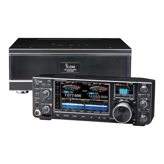
Icom IC-7760 Basic Manual
Hf/50 mhz transceiver
Hide thumbs
Also See for IC-7760:
- Advanced manual (116 pages) ,
- Operating manual (38 pages) ,
- Reference manual (27 pages)
Table of Contents
Advertisement
Quick Links
Advertisement
Table of Contents

Subscribe to Our Youtube Channel
Related Manuals for Icom IC-7760


Summary of Contents for Icom IC-7760
- Page 1 BASIC MANUAL HF/50 MHz TRANSCEIVER |7760...
-
Page 2: Important
Thank you for choosing this Icom product. This SUPPLIED ACCESSORIES product is designed and built with Icom’s state of the art technology and craftsmanship. With proper care, this product should provide you with years of trouble- free operation. Desktop stand... -
Page 3: Explicit Definitions
• Increase the separation between the equipment • The use of Icom transceivers with any equipment that is and receiver. not manufactured or approved by Icom. • Connect the equipment into an outlet on a circuit different from that to which the receiver is connected. -
Page 4: About Spurious Signals
TIP: You can download each manual and guide from the Icom website. https://www.icomjapan.com/support/ Enter “IC-7760” into the Search box in the site. • Basic manual (This manual) Instructions for basic operations. ABOUT THE TOUCH SCREEN •... -
Page 5: About The Instructions
ABOUT THE INSTRUCTIONS The Advanced and Basic manuals are described in 3. Touch “Time Set.” the following manner. “ ” (Quotation marks): Used to indicate icons, setting items, and screen titles displayed on the screen. The screen titles are also written in uppercase letters. (Example: FUNCTION screen) [ ] (brackets): Used to indicate keys. -
Page 6: Keyboard Entering And Editing
KEYBOARD ENTERING AND EDITING Keyboard types: You can select the Full Keyboard or the Tenkey pad in “Screen Keyboard Type” on the FUNCTION screen. (p. 8-7) » SET > Function > Screen Keyboard Type MENU L You can also temporarily switch the type in the QUICK MENU screen by pushing QUICK L You can select the full keyboard layout in “Screen Full... -
Page 7: Usable Characters
USABLE CHARACTERS You can enter and edit the items in the following table. Maximum Menu Item Selectable characters characters Network Name A to Z, 0 to 9, ! " # $ % & ( ) + , - . ; = @ [ ] ^ Network User 1/2 ID [AB] [ab] [12] [!″#] •... -
Page 8: Table Of Contents
Selecting the IF filter shape ....... 4-5 D Connecting the IC-PW2......... 2-3 Notch Filter ............4-6 D Connecting a non-Icom linear amplifier ..2-4 D Selecting the Notch filter type......4-6 Connecting a Transverter ........2-4 D Setting the Manual Notch filter ...... 4-6 BASIC OPERATION �����������������������������������������... - Page 9 DPD function ............. 4-9 USB Flash Drive ..........8-18 D Turning the DPD function ON or OFF ... 4-9 Others .............. 8-18 Digital Selector ..........4-9 CLOCK �������������������������������������������������������������� 9-1 D Adjusting the center frequency ...... 4-9 Setting the date and time ........9-1 Split frequency operation .........
-
Page 10: Precautions
CAUTION: DO NOT set the transceiver’s RF output Immediately turn OFF the power and/or remove the power to more than a connected linear amplifier’s power cables. Contact your Icom dealer or distributor maximum input level. Otherwise, the linear amplifier for advice. -
Page 11: Installation Notes
INSTALLATION NOTES DO NOT push PTT unless you actually intend to For amateur base station installations it is recommended that the forward clearance in front of the antenna array is transmit. calculated relative to the EIRP (Effective Isotropic Radiated Power). The clearance height below the antenna array can NEVER leave the transceiver in an insecure place to be determined in most cases from the RF power at the avoid use by unauthorized persons. -
Page 12: Panel Description
PANEL DESCRIPTION Front panel (Controller/RF deck) Controller Main screen Sub screen (p. 1-5) (p. 1-10) 11 12 17 18 20 21 22 23 24 1 POWER KEY (p. 3-1) 10 VOLUME CONTROL/MUTE KEY POWER RF/SQL z Push to turn ON the controller. L The upper control is for the Main band, and the lower is for the Sub band. - Page 13 PANEL DESCRIPTION Front panel (Controller/RF deck) 17 VOICE MEMORY RECORD KEY 32 MULTI-FUNCTION CONTROL MULTI z Push to save the previously received signal for z Push to open the Multi-function menu for various the preset time period set in REC Time using the adjustments.
-
Page 14: Rear Panel (Controller)
Input the audio signal to the internal modulator L Confirm the Network settings before connect to a circuit. network. 7 SEND JACK [SEND] (p. 13-6) Connect to control transmit with non-Icom external NOTE: Confirm that the transceiver is OFF before units. connecting or disconnecting optional equipment. -
Page 15: Rear Panel (Rf Deck)
L This is located between the transmit/receive switching 7 ALC JACK [ALC] (p. 13-3) circuit and receiver’s RF stage. Connect to the ALC output jack of a non-Icom linear 15 TRANSVERTER CONNECTOR [X-VERTER] amplifier. (pp. 2-4, 13-2) 8 STRAIGHT KEY JACK [KEY] (p. 13-3) Connect to an external transverter for input/output. -
Page 16: Touch Screen Display (Main Screen)
PANEL DESCRIPTION Touch screen display (Main screen) 10 11 1 MULTI-FUNCTION KEY GROUP (p. 1-8) 12 FUNCTION INDICATOR FOR MULTI-FUNCTION CONTROL (p. 1-9) Displays the Multi-function keys. L Touch to turn the function ON or OFF. Displays the function that is assigned to MULTI 2 ANTENNA INDICATOR (pp. - Page 17 PANEL DESCRIPTION Touch screen display (Main screen) 24 2327 22 VFO/MEMORY ICONS (p. 3-1) 34 RIT ICON (p. 4-1) Displays “VFO” when the VFO mode is selected, Displayed when the Receive Increment Tuning and displays the selected memory channel number (RIT) function is ON.
-
Page 18: D Menu Screen
PANEL DESCRIPTION Touch screen display (Main screen) D MENU screen D FUNCTION screen Function name Status Lights blue when in use z Push to open the FUNCTION screen in FUNCTION the selected mode. L To close the FUNCTION screen, push EXIT L You cannot use keys displayed in gray. -
Page 19: D Multi-Function Menus
PANEL DESCRIPTION Touch screen display (Main screen) D Multi-function menus D Multi-function key group Touch the edge to turn ON or OFF Touch the edge to turn ON or OFF Multi-function menu Multi-function key group z Touch a key to turn the function ON or OFF. z Open the Multi-function menu by pushing MULTI z Touching “ATT,”... -
Page 20: Multi-Function Dial
PANEL DESCRIPTION Multi-function dial Assignable key functions When the Multi-function menu is closed, the MULTI control can be enabled to adjust functions. MULTI * Touch the function indicator, or hold down for 1 The function is displayed in the upper right corner of second to assign the function to the control. -
Page 21: Touch Screen Display (Sub Screen)
PANEL DESCRIPTION Touch screen display (Sub screen) You can display one of the following screens on the D Keypad screen Sub screen for your convenience. You can select the operating band by pushing once, • Filter Effect screen or call up other stacked frequencies by pushing the •... -
Page 22: Installation And Connections
INSTALLATION AND CONNECTIONS Selecting a location Heat dissipation • NEVER install the transceiver in a place without CAUTION: Always have 2 people carry, lift, or turn adequate ventilation. Heat dissipation may be over the RF deck. reduced, and the transceiver may be damaged. •... -
Page 23: Connecting The Controller And Rf Deck
DO NOT connect the controller’s [RF DECK] port to the RF deck’s [LAN] port with the supplied control cable. L The RF deck’s [LAN] port is used to connect the IC-7760 to a network (LAN or Internet). See the Advanced manual for details about how to connect the controller and RF deck through a network. -
Page 24: Connecting A Linear Amplifier
To connect the second Icom exciter, use the optional OPK-5 cable kit. When connecting the IC-7760 to both [INPUT 1] and [INPUT 2] To operate the amplifier in synchronization with the IC-7760’s frequency data, disconnect the AH-730, and then set “IC-PW2 Dual Connection Mode” to “ON.”... -
Page 25: D Connecting A Non-Icom Linear Amplifier
• The maximum signal level of the [SEND] jack is 16 V/0.5 A DC with the “Reed” setting, and 250 V/200 mA with the “MOSFET” setting. Use an external unit if your non-Icom linear amplifier requires a control voltage and/or current greater than specified. -
Page 26: Basic Operation
BASIC OPERATION When first applying power Adjusting the volume level Before turning ON your transceiver for the first time, Rotate (inner) to adjust the volume level. RF/SQL make sure all connections are correctly made. After all connections are made, set the dials to the Selecting the mode positions described below. -
Page 27: Selecting The Main And Sub Bands
Dualwatch operation bands Dualwatch simultaneously monitors two frequencies. The IC-7760 has 2 independent receiver circuits, the The IC-7760 has 2 identical receivers, Main and Main and Sub bands, so that you can use Dualwatch Sub. The Main band is displayed on the left side of... -
Page 28: Selecting The Operating Band
BASIC OPERATION Selecting the operating band D Selecting the operating band on the D Selecting the operating band on the Sub screen Main screen 1. Push several times to display the 1. Touch the MHz digits. (Example: 21) SUB DISP Keypad screen. -
Page 29: Selecting The Operating Mode
BASIC OPERATION Selecting the operating mode You can select between the SSB (LSB/USB), SSB Selecting the Data mode data (LSB-D/USB-D), CW, CW reverse, RTTY, RTTY You can operate data communications (SSTV, RTTY reverse, PSK, PSK reverse, AM, AM data (AM-D), FM, (AFSK), PSK31, JT65B, and FT8). -
Page 30: Setting The Frequency
BASIC OPERATION Setting the frequency D Using the Main Dial D About the 1 Hz step Fine Tuning function 1. Select the desired operating band. (p. 3-3) 2. Rotate MAIN DIAL You can use the minimum tuning step of 1 Hz for fine •... -
Page 31: D Directly Entering A Frequency
BASIC OPERATION Setting the frequency D Directly entering a frequency You can set the frequency without rotating MAIN DIAL by directly entering it using the keypad. Entering the operating frequency on the Sub Entering the operating frequency on the Main screen screen 1. - Page 32 BASIC OPERATION Setting the frequency D Directly entering a frequency Entering the Split Frequency Offset on the Main Entering the Split Frequency Offset on the Sub screen screen 1. Touch the MHz digits. (Example: 14) 1. Push several times to display the SUB DISP •...
-
Page 33: Rf Gain And Sql Level
BASIC OPERATION RF gain and SQL level Setting the frequency Rotate (outer) to adjust the RF gain and D Directly entering a frequency RF/SQL SQL level. Selecting a Memory channel by number By default, rotating to the left (when set to the 12 1. -
Page 34: Selecting The Antenna Connector
BASIC OPERATION Selecting the antenna connector Dial Lock function Set the antenna connector to between “ANT 1” and The Dial Lock function prevents frequency changes “ANT 4,” and turn the receive antenna connector ON caused by accidentally moving MAIN DIAL or OFF. -
Page 35: Adjusting The Transmit Output Power
BASIC OPERATION Adjusting the transmit output Transmit Power Limit function power The Transmit Power Limit function limits the output power to the preset level for each band. Before transmitting, monitor your selected operating frequency to make sure you do not cause 1. -
Page 36: Meter Display On The Main Screen
BASIC OPERATION Meter display on the Main screen D Selecting the Meter display D Multi-function meter You can display one of the 6 different transmit You can simultaneously display all the parameters. parameters (Po, SWR, ALC, COMP, Vd, and Id) for L The TEMP meter is also displayed on the Multi-function meter. -
Page 37: Receiving And Transmitting
RECEIVING AND TRANSMITTING Preamplifiers RIT function The preamp amplifies received signals in the receiver The Receiver Incremental Tuning (RIT) function front end to improve the signal-to-noise ratio and compensates for differences in frequencies of other sensitivity. A preamp is used when receiving weak stations. -
Page 38: Agc Function Control
RECEIVING AND TRANSMITTING AGC function control D Setting the AGC time constant SSB, CW, RTTY, PSK, and AM modes The Automatic Gain Control (AGC) function controls You can set the preset AGC time constant to a desired receiver gain to produce a constant audio output level, value. -
Page 39: Setting The Speech Compressor
RECEIVING AND TRANSMITTING Setting the Speech Compressor D Using the Speech Compressor function SSB mode The Speech Compressor increases the average RF 1. Touch the meter, and then touch [COMP] to output power, improving readability at the receiving display the COMP meter. station. -
Page 40: Using The Digital Twin Pbt
Tuning (PBT) narrows the IF passband width by change the IF passband width, using the Digital Twin electronically shifting the IF frequency to slightly PBT. above or below the IF center frequency. The IC-7760 Passband width uses the digital function using the FPGA (Field Shift value Programmable Gate Array) filtering method. -
Page 41: Selecting The If Filter
SSB, CW, RTTY, PSK, and AM modes Mode IF filter Selectable range (steps) The IC-7760 has 3 IF filter passband widths for FIL 1 (3.0 kHz) each mode, and you can select them on the FILTER 50 Hz to 500 Hz (50 Hz)/ FIL 2 (2.4 kHz) -
Page 42: Notch Filter
RECEIVING AND TRANSMITTING Notch Filter The IC-7760 has Auto Notch and Manual Notch D Using the Filter Effect screen functions. When Manual Notch is selected, you can visually Auto Notch automatically attenuates beat tones, check that the Notch function removes the set tuning signals, and so on. -
Page 43: Noise Blanker
RECEIVING AND TRANSMITTING Noise Blanker NB is OFF NB is ON (Effective) SSB, CW, RTTY, PSK, and AM modes The Noise Blanker eliminates pulse-type noise, such Pulse-type noise NB LEVEL Desired signal as the noise from car ignitions. Desired signal Noise removed z Push •... -
Page 44: Setting The Transmit Filter Width
RECEIVING AND TRANSMITTING Setting the transmit filter width Monitor function SSB mode SSB, RTTY, PSK, AM, and FM modes The transmit filter width for the SSB and SSB-D The Monitor function enables you to monitor your modes can be set. WIDE (wide), MID (mid), or NAR transmit audio. -
Page 45: Dpd Function
RECEIVING AND TRANSMITTING DPD function Digital Selector You can manually adjust the center frequency of SSB and AM modes The Digital Pre-Distortion (DPD) function reduces the automatic preselector using the Digital Selector the distortion of the SSB, SSB-D, AM, or AM-D mode function. -
Page 46: Split Frequency Operation
RECEIVING AND TRANSMITTING Split frequency operation Split frequency operation enables you to transmit and There are 2 ways to use Split frequency operation. receive on different frequencies on the Main and the • Use the Quick Split function. Sub bands. •... -
Page 47: Split Lock Function
RECEIVING AND TRANSMITTING Split Lock function Operating CW To prevent accidentally changing the receive D Setting the CW pitch control frequency by releasing while rotating MAIN DIAL You can set the received CW audio pitch and the CW use the Split Lock function. Using both this function side tone to suit your preference, without changing the and the Dial Lock function enables you to change only operating frequency. -
Page 48: D Using The Break-In Function
The IC-7760 is capable of operating in the Semi Break-in and Full break-in modes. 1. Select the CW mode. -
Page 49: D Audio Peak Filter (Apf) Operation
RECEIVING AND TRANSMITTING Operating CW D Audio Peak Filter (APF) operation D About the electronic Keyer function The APF enables you to set excellent selectivity in the You can set the Memory Keyer function settings, CW mode. You can set the selectivity to between the paddle polarity settings, and so on of the Electronic 3 APF passband widths. -
Page 50: Scope Operation
SCOPE OPERATION Spectrum scope screen The spectrum scope enables you to display the D Using the Spectrum Scope activity on the selected band, as well as the relative Display the SPECTRUM SCOPE screen. strengths of various signals in that band. »... -
Page 51: D Marker
SCOPE OPERATION Audio scope screen Spectrum scope screen D Marker This audio scope enables you to display the received signal’s frequency component on the FFT scope, and The Marker displays the operating frequency for both its waveform components on the Oscilloscope. The the Main and Sub bands in the SPECTRUM SCOPE FFT scope also has a waterfall. -
Page 52: Sd Card/Usb Flash Drive
• Voice audio for the Voice TX function You can use an SD card of up to 2 GB, or an SDHC • RTTY and PSK decode log of up to 32 GB. Icom has checked the compatibility of • Captured screens the following cards. -
Page 53: Formatting
SD CARD/USB FLASH DRIVE Formatting Unmounting Before using an SD card or USB flash drive, format it Before you remove a card when the transceiver is ON, to be used with the transceiver by doing the following be sure to electrically unmount it, as shown below. steps. -
Page 54: Antenna Tuner Operation
ANTENNA TUNER OPERATION About the Antenna memory settings This function saves antenna connector settings for D Saving an antenna connector setting each frequency band. You can set antenna connectors Example: Assigning ANT2 to the 10 MHz band. ANT1 ~ ANT4, ANT1/R ~ ANT4/R, or ANT1 ANT4 to selected bands. -
Page 55: D Setting The Antenna Type
ANTENNA TUNER OPERATION About the Antenna memory settings D Setting the antenna type On this screen, you can set the type of antenna to use. 1. Open the ANTENNA screen. ANT2 Connector (Default: ON) » ANTENNA ANT3 Connector (Default: ON) MENU ANT4 Connector (Default: ON) -
Page 56: About The Internal Antenna Tuner
ANTENNA TUNER OPERATION About the internal antenna tuner The internal automatic antenna tuner automatically D Using the Internal antenna tuner matches the transceiver to the antenna within the 1. Push to turn ON the internal antenna TUNER range of 16.7 ~ 150 Ω (SWR of less than 1:3). tuner. -
Page 57: About The External Antenna Tuner
About the external antenna tuner The optional AH-730 antenna tuner matches the D Using the IC-PW2 IC-7760 to a long wire antenna more than 7 m/23 ft When you use the internal antenna tuner of the long (1.8 MHz to 54 MHz). -
Page 58: Set Mode
SET MODE Set mode description You can use the Set mode to set infrequently changed TIP: The Set mode is constructed in a tree structure. values or function settings. You can go to the next tree level, or go back a level, depending on the selected item. -
Page 59: Tone Control/Tbw
SET MODE CW-KEY Set NOTE: The default settings shown below are for the USA transceiver version. The default settings may differ, depending on your transceiver version. L You can also set the same items in the CW-KEY SET menu on the KEYER screen. (p. 4-13) Tone Control/TBW »... -
Page 60: Paddle Polarity
SET MODE Function CW-KEY Set » SET > Function Paddle Polarity (Default: Normal) MENU Sets the paddle dot-dash polarity to Normal or Beep Level (Default: 50%) Reverse. • Normal: Right = dash, Left = dot Sets the beep output level. •... - Page 61 L If an external equipment’s rise time is slower than that (Default: All Volume Levels) of the IC-7760, a reflected wave is produced, and it may While remotely controlling the transceiver, sent CI-V damage the IC-7760 or the external device. To prevent commands override some of the control dials’...
-
Page 62: Split Lock
SET MODE RTTY Mark Frequency (Default: 2125) Function Selects the RTTY mark frequency. L When the internal RTTY decoder is used, 2125 Hz is automatically selected. » SET > Function > SPLIT MENU SPLIT LOCK (Default: OFF) RTTY Shift Width (Default: 170) Turns the Split Lock function ON or OFF. -
Page 63: Lock Function
SET MODE » SET > Function Quick RIT/∂TX Clear (Default: OFF) MENU Selects the operation for the RIT and ∂TX CLEAR [SPEECH/LOCK] Switch (Default: SPEECH/LOCK) functions. • OFF: Holding down for 1 second resets the Selects action. CLEAR SPEECH RIT or ∂TX shift frequency. •... - Page 64 SET MODE The assignable key functions for Front Key: Function Function Description » SET > Function > MIC Key Customize MENU Push to turn the VOX function in the Voice operation modes and the Break-in function [UP] (Default: UP (VFO: kHz)) VOX/BK-IN* in the CW mode ON or OFF.
- Page 65 SET MODE The assignable key functions for MIC Key: Function Description Function Description No function In the SSB, AM, or FM mode • Push to transmit the voice audio Voice/Keyer/ Push to increase the frequency (in 50 Hz recorded on the SD card once. RTTY/PSK steps*) or Memory channel.
-
Page 66: Dpd Adjustment
» SET > DPD Adjustment MENU Selects the signal output from the [USB B] port on the controller’s rear panel. IC-7760 Single Adjustment • AF: An AF signal is output. Displays the screen for selecting the band for the DPD • IF: A 12 kHz IF signal is output. - Page 67 SET MODE » SET > Connectors > LINE-OUT AF/IF Output » SET > Connectors > ACC AF/IF Output MENU MENU AF Output Select AF/SQL Output Select (Default: MAIN) (Default: MAIN) Selects the audio signals to output from the Selects the audio and squelch signals to output from [LINE OUT] jack on the controller’s rear panel in the the [ACC 1] socket (Audio: pin 5, Squelch: pin 6) on Main and Sub bands.
- Page 68 Selects the signal output from the [LAN] connector. rear panel to your PC, the ports are virtually named • AF: An AF signal is output. “IC-7760 Serial Port A (CI-V)” and “IC-7760 Serial • IF: A 12 kHz IF signal is output.
- Page 69 CI-V Address (Default: B2h) Keyboard Type (Default: English) Sets the CI-V address in hexadecimal code. L “B2” is the default address of the IC-7760. Selects the keyboard language. CI-V Transceive (Default: ON) Keyboard Repeat Delay (Default: 250ms) Turns the Transceive function ON or OFF.
- Page 70 L If the applied reference signal is off frequency, or not high » SET > Connectors MENU enough, the IC-7760 will not work correctly. In that case, select “OFF.” USB (B) Function (Default: RTTY/PSK Decode) The transceiver has 2 virtual COM ports, A and B.
-
Page 71: Network
“IP Address (LAN),” “IP Address (Controller),” and “IP Address (RF Deck).” L Displayed only when “Connection from Different L When you are operating the IC-7760 using the optional Segment” is set to “ON.” RS-BA1, “IP Address (LAN)” is used to access. -
Page 72: Network Name
» SET > Network > Remote Settings MENU Network Radio Name (Default: IC-7760) Sets the IC-7760’s name of up to 16 characters that is displayed in the remote control software, when you L When in the Standby mode, the indicator on POWER remotely control the IC-7760. -
Page 73: Display
SET MODE » SET > Display Display MENU Screen Saver (Default: 60min) » SET > Display MENU Sets the Screen Saver function. This function activates and automatically turns OFF LCD Backlight (Default: 50%) the screen when no operation is performed for the Sets the LCD backlight brightness. -
Page 74: Time Set
SET MODE Time Set SD Card » SET > Time Set > Date/Time » SET > SD Card MENU MENU Date Load Setting Sets the date (Year/Month/Day). Selects the saved data file to load. L The day of the week is automatically set. Save Setting Time Saves the setting data onto an SD card. -
Page 75: Usb Flash Drive
SET MODE USB Flash Drive Others » SET > USB Flash Drive » SET > Others > Information MENU MENU Load Setting Version Selects the saved data file to load. Displays the transceiver firmware’s version number. Save Setting MAC Address (LAN) MAC Address (Controller) Saves the setting data onto a USB flash drive. -
Page 76: Clock
EXIT several times. NOTE: The backup battery for the internal clock The IC-7760 has a lithium backup battery (CR2032) for the internal clock and timer functions. When the backup battery is exhausted, the transceiver normally works but cannot retain the •... -
Page 77: D Setting The Clock2 Utc Offset
CLOCK Setting the date and time D Setting the CLOCK2 UTC offset D Editing the CLOCK2 name Set the time offset for CLOCK2 to the same as the You can edit CLOCK2’s 3 character name. The default current time. name is “UTC.” 1. -
Page 78: Maintenance
MAINTENANCE Cleaning DO NOT use harsh solvents such as If the transceiver becomes dusty or dirty, benzine or alcohol when cleaning, wipe it clean with a dry, soft cloth. because they will damage the transceiver surfaces. Resetting D Partial reset Occasionally, erroneous information may be displayed. -
Page 79: Troubleshooting
The following chart is designed to help you solve problems that are not equipment malfunctions. If you are unable to locate the cause of a problem or solve it through the use of this chart, contact your nearest Icom Dealer or Service Center. L “AM” indicates the PDF type Advanced manual. - Page 80 MAINTENANCE Troubleshooting Problem Possible cause Solution REF. A receive antenna cannot be select. “RX-ANT Connectors” is set to Set to “Connect Receive Antenna” p. 7-2 “Connect External RX Device.” (default). The MAIN/SUB indicator blinks blue. The Tracking function is ON. Turn OFF the function.
- Page 81 MAINTENANCE Troubleshooting Problem Possible cause Solution REF. A Memory scan does not start. The Memory mode is not selected. Select the Memory mode. p. 3-1 No, or only 1 memory channel is set. Set at least 2 memory channels. A Select memory scan does not start. No, or only 1 memory channel is Assign at least 2 memory channels assigned as a Select channel.
- Page 82 Check the network switch settings. be connected between different incorrect. L They cannot be connected through segments. the Internet. “The connection to the RF deck has – Contact your nearest Icom Dealer or – been lost” is repeatedly displayed. Service Center. 10-5...
-
Page 83: Specifications
SPECIFICATIONS D General • Frequency coverage (unit: MHz): Receiver 0.030000 ~ 60.000000 Transmitter 0.135700 ~ 0.137800* (Only in the European version) 1.800000 ~ 1.999999* 3.500000 ~ 3.999999* 5.255000 ~ 5.405000 (Only in the USA version) 7.000000 ~ 7.300000* 10.100000 ~ 10.150000 14.000000 ~ 14.350000 18.068000 ~ 18.168000 21.000000 ~ 21.450000... -
Page 84: D Receiver
SPECIFICATIONS D Receiver • Receive system: RF Direct Sampling Super Heterodyne • Intermediate frequency: 1st 12 kHz • Sensitivity: SSB/CW (BW=2.4 kHz, at 10 dB S/N) 135/475 kHz band +3 dBμV (1.41 μV) typical 1.800000 ~ 29.999999 MHz –16 dBμV (0.16 μV) typical 50 MHz band –18 dBμV (0.13 μV) typical AM (BW=6 kHz, at 10 dB S/N) -
Page 85: Options
OPTIONS Options (As of October 2024) IC-PW2 SP-41 HM-219 LINEAR AMPLIFIER EXTERNAL SPEAKER MICROPHONE SM-30 SM-50 AH-730 RC-28 DESKTOP MICROPHONE DESKTOP MICROPHONE AUTOMATIC ANTENNA REMOTE ENCODER TUNER Set “External Antenna Tuner For operating the RS-BA1 Desktop microphone with a Dynamic microphone with Connection”... -
Page 86: Connector Information
SET > Connectors > ACC AF/IF Output > MENU Example: ACC 1/2 socket Output Select To a non-Icom linear amplifier You can change the AF/IF (IF=12 kHz) output level. 3 SEND LApproximately 200 mV rms is at 50% as the default. -
Page 87: D [Ant 1]/[Ant 2]/[Ant 3]/[Ant 4]
CONNECTOR INFORMATION RF Deck D [ANT 1]/[ANT 2]/[ANT 3]/[ANT 4] D [RX-ANT IN]/[RX-ANT OUT] Connect an antenna for the HF and 50 MHz bands. Connect a receive antenna to [RX-ANT IN], and a receiver to [RX-ANT OUT]. • Input/Output impedance: 50 Ω... -
Page 88: D [Tuner]
Connect a PC’s USB port, to demodulate the DRM signal. broadcast or Software Defined Radio SDR. • Remotely controlling using optional RS-BA1 L Icom does not provide any support regarding SDR software. technology and related software, except the inspection for the normality of output signal. -
Page 89: Controller
5 PTT Sub band signal 4 Squelch line output Main band signal NOTE: Pin 1 outputs 8 V DC power for Icom L While headphones are connected, both the internal and microphones. external speakers are deactivated. L You can turn OFF the DC power when you use non- L If you use headphones with high impedance, the output Icom microphones the following item. -
Page 90: D [Usb A]
USB HDD, or Bluetooth keyboard or mouse, as » SET > Connectors > External Keypad MENU these are not supported by Icom. L The external keypad shown below is not supplied by • DO NOT connect two or more of the same USB devices. Icom. -
Page 91: D [Send]
L You can change the AF/IF (IF=12 kHz) settings to output a 12 kHz IF signal. In that case, you can listen to DRM Example: [SEND] jack To a non-Icom communication with the application software receiver that linear amplifier is installed onto your PC. -
Page 92: D [Ext-Sp A]/[Ext-Sp B]
CONNECTOR INFORMATION Controller D [EXT-SP A]/[EXT-SP B] D [DC IN] Connect to external speakers. Connect the supplied power cable to an AC receptacle. 3.5 mm (1/8 inch) • Output impedance: 4 ~ 8 Ω • Output level: More than 2 W (8 Ω... -
Page 93: Index
INDEX 1/4 Tuning function ............3-5 Main band ................3-2 Main screen ...............1-5 AGC function ..............4-2 Memory mode..............3-1 AH-730 ..............2-2, 7-4 MENU screen ..............1-7 All reset................10-1 Meter ................3-11 Antenna Microphone gain ..............3-9 Memory screen .............7-1 Monitor function ..............4-8 Type ................7-2 Multi-function dial...............1-9 APF (Audio Peak Filter) ...........4-13 Multi-function key group ............1-8... -
Page 94: About The Licenses
ABOUT THE LICENSES Information on the open source software Permission is hereby granted to use, copy, INTERRUPTION) HOWEVER CAUSED mode (with the -n32 compiler flag). being used by this product. modify, and distribute this source code, or AND ON ANY THEORY OF LIABILITY, The compiler bug has been reported to portions hereof, for any purpose, without WHETHER IN CONTRACT, STRICT... - Page 95 ABOUT THE LICENSES mbed TLS representatives, including but not limited NOTICE text file distributed as part losses), even if such Contributor has to communication on electronic mailing of the Derivative Works; within the been advised of the possibility of such lists, source code control systems, and Source form or documentation, if damages.
- Page 96 How the World Communicates A7788H-1EX Printed in Japan 1-1-32 Kamiminami, Hirano-ku, Osaka 547-0003, Japan © 2024 Icom Inc. Oct. 2024...
Need help?
Do you have a question about the IC-7760 and is the answer not in the manual?
Questions and answers