Sign In
Upload
Download
Table of Contents
Contents
Add to my manuals
Delete from my manuals
Share
URL of this page:
HTML Link:
Bookmark this page
Add
Manual will be automatically added to "My Manuals"
Print this page
×
Bookmark added
×
Added to my manuals
Manuals
Brands
BluStream Manuals
Control Unit
Multicast ACM200
User manual
BluStream Multicast ACM200 User Manual
Advanced control module
Hide thumbs
Also See for Multicast ACM200
:
User manual
(59 pages)
,
Api documentation
(19 pages)
1
Table Of Contents
2
3
4
5
6
7
8
9
10
11
12
13
14
15
16
17
18
19
20
21
22
23
24
25
26
27
28
29
30
31
32
33
34
35
36
37
38
39
40
41
42
43
44
45
46
47
48
49
50
51
52
page
of
52
Go
/
52
Contents
Table of Contents
Bookmarks
Table of Contents
Table of Contents
Introduction
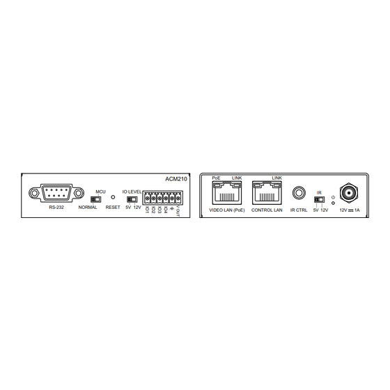
Panel Descriptions - ACM200 / ACM210
Control Ports
Web-GUI - Menu Overview
Web-GUI - Drag & Drop Control
Web-GUI - Video Wall Control
Web-GUI - Preview
Web-GUI - Project Summary
Web-GUI - Transmitters
Web-GUI - Receivers
Web-GUI - Fixed Signal Routing
Web-GUI - Video Wall Configuration
Web-GUI - Users
Web-GUI - Settings
Web-GUI - Update Firmware
Advertisement
Quick Links
1
Introduction
2
Web-Gui - Settings
3
Web-Gui - Update Firmware
Download this manual
PoE
LINK
LINK
ACM210
MCU
IO LEVEL
IR
RS-232
NORMAL
RESET
5V 12V
VIDEO LAN (PoE)
CONTROL LAN
IR CTRL
5V 12V
12V
1A
Blustream Multicast ACM200 / ACM210
Advanced Control Module
User Manual
Revision 1.3 - August 2023
M U L T I C A S T
Table of
Contents
Previous
Page
Next
Page
1
2
3
4
5
Advertisement
Table of Contents
Need help?
Do you have a question about the Multicast ACM200 and is the answer not in the manual?
Ask a question
Questions and answers
Related Manuals for BluStream Multicast ACM200
Media Converter BluStream Multicast ACM200 User Manual
Advanced control module (59 pages)
Control Unit BluStream Multicast ACM200 Api Documentation
Advanced control module (19 pages)
Control Unit BluStream ACM500 Quick Reference Manual
(4 pages)
Control Unit BluStream Multicast ACM500 User Manual
Advanced control module for use with ip500uhd systems (57 pages)
Control Unit BluStream Multicast ACM210 User Manual
Advanced control module (52 pages)
This manual is also suitable for:
Multicast acm210
Table of Contents
Print
Rename the bookmark
Delete bookmark?
Delete from my manuals?
Login
Sign In
OR
Sign in with Facebook
Sign in with Google
Upload manual
Upload from disk
Upload from URL


Need help?
Do you have a question about the Multicast ACM200 and is the answer not in the manual?
Questions and answers