Canon imageRUNNER ADVANCE 715iF III Series Service Manual
Hide thumbs
Also See for imageRUNNER ADVANCE 715iF III Series:
- Faq manual (92 pages) ,
- Getting started (12 pages)

Related Manuals for Canon imageRUNNER ADVANCE 715iF III Series


Summary of Contents for Canon imageRUNNER ADVANCE 715iF III Series
- Page 1 ADVANCE 715iF III Series SERVICE MANUAL Canon February 22, 2023 Rev. 10 CANON imageRUNNER ADVANCE 715iF III Series Rev. 10 PRINTED IN U.S.A. COPYRIGHT 2023 CANON INC. ©...
- Page 2 When changes occur in applicable products or in the contents of this manual, Canon will release technical information as the need arises. In the event of major changes in the contents of this manual over a long or short period, Canon will issue a new edition of this manual.
- Page 3 Important Notices Explanation of Symbols The following symbols are used throughout this Service Manual. Symbols Explanation Symbols Explanation Check. Remove the claw. Check visually. Insert the claw. Check a sound. Push the part. Disconnect the connector. Connect the power cable. Connect the connector.
- Page 4 Important Notices 2. In the digital circuits, '1' is used to indicate that the voltage level of a given signal is "High", while '0' is used to indicate "Low". (The voltage value, however, differs from circuit to circuit.) In addition, the asterisk (*) as in "DRMD*" indicates that the DRMD signal goes on when '0'.
-
Page 5: Table Of Contents
Contents Contents Safety Precautions....................1 Laser..............................2 Laser Safety............................2 How to Handle the Laser Scanner Unit....................2 Power Supply / Lithium Battery......................3 Power Supply Guidelines........................3 Notes When Handling a Lithium Battery....................3 Toner Safety............................3 About Toner............................3 Handling Adhered Toner........................3 Notes on works............................4 Points to Note Before Servicing......................4 Points to Note at Cleaning........................ - Page 6 Contents Shutdown Sequence........................... 44 Motion Sensor.............................44 Laser Exposure System........................46 Overview............................46 Laser ON/OFF Control.........................46 Scanner Motor Control.........................47 APC (Auto Power Control)........................47 BD Detection Correction Control......................48 Image Formation System........................49 Overview............................49 Cartridge............................50 Transfer..............................52 Image Stabilization Control........................54 Fixing System............................55 Features.............................55 Fixing temperature control........................
- Page 7 Contents 4. Parts Replacement and Cleaning..............93 Preface.............................. 94 Outline............................... 94 Parts List............................95 List of Cover (with Finisher)......................... 95 List of Cover (without Finisher)......................97 Main Unit............................99 ADF..............................101 Reader............................. 102 PCB..............................103 Switch.............................. 105 Fan..............................107 Motor..............................108 Sensor..............................109 Motor (with Finisher)..........................110 Sensor (Finisher)..........................111 Others (Finisher)..........................
- Page 8 Contents Removing the Low-Voltage Power Supply PCB................... 189 Removing the Inlet Unit........................190 Removing the DC Controller PCB.......................192 Removing the High-Voltage Power Supply PCB.................. 192 Removing the FAX Unit........................193 Controller System (Finisher)......................197 Removing the Finisher Controller PCB....................197 Laser Exposure System........................198 Removing the Laser Scanner Unit......................
- Page 9 Contents Remedies to be performed when E602-xxxx or E614-xxxx error is displayed.........243 Test Print............................248 Overview............................248 How to use the test print........................249 Startup System Failure Diagnosis....................253 Overview............................253 Basic Flow of Startup System Failure Diagnosis ................. 254 Control Panel LED Check Flow......................
- Page 10 Contents I/O..............................420 ADJUST (Adjustment mode)......................421 FUNCTION (Operation / inspection mode)..................471 OPTION (Specification setting mode)....................491 TEST (Print test mode)........................581 COUNTER (Counter mode)....................... 585 FEEDER (ADF service mode)......................604 DISPLAY (State display mode)......................604 ADJUST (Adjustment mode)......................604 FUNCTION (Operation / inspection mode)..................606 OPTION (Specification setting mode)....................
- Page 11 Contents Checking after Installation ......................... 666 Copy Control Interface Kit-A1......................668 Installation Outline Drawing........................668 Checking the Contents........................668 Essential Items to Be Performed Before Installation................668 Installation Procedure........................669 Connection Kit-A1/A2/A3 for Bluetooth LE ..................672 Points to Note at Installation ......................672 Installation Outline Drawing........................672 Essential Items to Be Performed Before Installation................672 Checking the Contents ........................673 Installation Procedure ........................
-
Page 12: Safety Precautions
Safety Precautions Laser............. 2 Power Supply / Lithium Battery..... 3 Toner Safety..........3 Notes on works........4... -
Page 13: Laser
Safety Precautions Laser Laser Safety Since radiation emitted inside this machine is completely confined with protective housings and external covers, the laser beam cannot escape from the machine during any phase of normal use by users. Therefore, this machine is classified as a Class 1 laser product under the international standard IEC60825-1 that is regarded as safe during normal use. -
Page 14: Power Supply / Lithium Battery
Safety Precautions Power Supply / Lithium Battery Power Supply Guidelines • As a general rule, do not use extension cords. If an extension cord must be used, one that meets the rated voltage and current of the product must be used. When using, untie the bundle and plug the power cord into the root to ensure the connection between the power cord and extension cord. -
Page 15: Notes On Works
Safety Precautions Notes on works Points to Note Before Servicing • At servicing, be sure to turn OFF the power source according to the specified steps and disconnect the power plug. • Be sure to disconnect the power plug on a regular basis and remove dust and dirt accumulated around the outlet with dry cloth. -
Page 16: Product Overview
Product Overview Product Lineup........6 Specifications........10 Parts Name......... 19... -
Page 17: Product Lineup
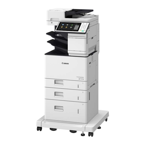
1. Product Overview Product Lineup Host Machine Product name imageRUNNER ADVANCE 715III / 615III / 525III The underlined numerical value indicates the print speed (ppm: page per minute). Model 525 III 715i III/ 615i III / 525i 715iF III / 615iF III / 715iFZ III / 615iFZ III / 715iZ III / 615iZ III / 525iF III... -
Page 18: Pickup/Delivery / Image Reading System Options
1. Product Overview Pickup/Delivery / Image Reading System Options Product name ADF Access Handle-A1 Cassette Module-AG1 Envelope Cassette Module-A1 High Capacity Cassette Feeding Unit-D1 Cassette Feeding Unit-AR1 Combination of installable pickup options Host machine model Combination of installable pickup options 715I / 615I / 525I / 715IF / 615IF / 525IF Install a [2] Cassette Module-AG1 only Install 2 [2] Cassette Module-AG1s... -
Page 19: Function Expansion System Options
1. Product Overview Host machine model Combination of installable pickup options 715I / 615I / 525I / 715IF / 615IF / 525IF Install both [2] Cassette Module-AG1 and [3] Envelope Cassette Module-A1 Install a [4] High Capacity Cassette Feeding Unit-D1 only Install a [5] Cassette Feeding Unit-AR1 only 715IFZ / 615IFZ / 525IFZ / 715IZ / 615IZ / 525IZ Install a [2] Cassette Module-AG1 only... - Page 20 1. Product Overview Product name NFC Kit-C1 Copy Card Reader Attachment-B5 Copy Card Reader-F1 Copy Control Interface Kit-A1 IC Card Reader Box-D1 IC Card Reader Attachment-A1 Super G3 FAX Board-AY1 Connection Kit-A1 for Bluetooth LE Power Supply Cable-V1 Remote Fax Kit-A1 IP FAX Expansion Kit-B1 PCL International Font Set-A1 Picture Login-A1...
-
Page 21: Specifications
1. Product Overview Specifications Host machine Item Specifications Machine installa- Desk-top tion method Photosensitive φ30mm, OPC medium Exposure method Semiconductor 4Beam Laser Charging method DC Roller Charging Developing meth- Dry, 1-component toner projection development Transfer method Roller Transfer Separation method Retard separation method without driving source Pickup method Stack bypass : Retard separation method Cassette : Retard separation method... -
Page 22: Fax Specifications
• Inch configuration: LGL, LTR, LTRR, STMTR Receiving Paper Sizes • A4, B5, A5, LGL, LTR, STMTR, 16K No. of Memory RX Jobs Up to 320 jobs Transmission Times Approximately 2.6 seconds (When sending LTR Canon original paper, Normal 8 pels x 3.85 line/mm, ECM (JBIG)) -
Page 23: Weight And Size
1. Product Overview *1 When using an IP telephone service, facsimile communication may not be performed normally via an IP telephone line. It is recommended to use facsimile communication via a general telephone (Public Switched Telephone Network) line. *2 Pels stands for picture elements (pixels). *3 Sent as A4. - Page 24 1. Product Overview Mode Mode 1-side 2-side CST/Optional CST/Optional Thick paper2 ( 121 to 135 g/m 6 to 40 6 to 31 Thick paper3 ( 136 to 163 g/m 6 to 40 6 to 35 Thick paper4 ( 164 to 199 g/m LTRR STMTR 3 to 27...
- Page 25 1. Product Overview Mode Mode 1-side 2-side CST/Optional CST/Optional BOND ( 75 to 90 g/m EXER 6 to 20 6 to 20 6 to 20 6 to 14 Thick paper2 ( 121 to 135 g/m Thick paper3 ( 136 to 163 g/m 6 to 35 6 to 24 Thick paper4 ( 164 to 199 g/m...
-
Page 26: Paper Type
1. Product Overview Mode Mode 1-side 2-side CST/Optional CST/Optional Plain3 ( 90 to 105 g/m STMTR 3 to 22 3 to 19 Thick paper1 ( 106 to 120 g/m EXER 6 to 33 6 to 23 6 to 27 6 to 15 Label ( 130 to 130 g/m K16R 6 to 33... -
Page 27: Available Paper Types
1. Product Overview Available Paper Types Type (paper weight: Size Pickup position g/m2) Multi-pur- Cassette 1 Cassette Cassette High Capacity D1 Envelope pose Tray CST 1 CST 2 Thin Paper (60 g/m Plain Paper 1 (61 to 74 Plain Paper 2 (75 to 89 Plain Paper 3 (90 to 105 g/ LTRR Heavy Paper 1 (106 to 120... - Page 28 1. Product Overview Type (paper weight: Size Pickup position g/m2) Multi-pur- Cassette 1 Cassette Cassette High Capacity D1 Envelope pose Tray CST 1 CST 2 Heavy Paper 2 (121 to 135 K16R I-LGL Custom paper size 1 Custom paper size 2 Custom paper size 3 Custom paper...
- Page 29 1. Product Overview Type (paper weight: Size Pickup position g/m2) Multi-pur- Cassette 1 Cassette Cassette High Capacity D1 Envelope pose Tray CST 1 CST 2 Heavy Paper 3 (136 to 163 Custom paper size 8 Custom paper size 9 Custom paper size 10 Heavy Paper 4 (164 to 199 LTRR...
-
Page 30: Parts Name
1. Product Overview Parts Name Cross Section View [16] [10] [11] [17] [12] [13] [14] [18] [15] Name ADF Unit Scanner Unit (Back Side) Reader Unit Scanner Unit (Front Side) Jogger Unit Upper Paper Feed Unit Staple Unit Lower Paper Feed Unit Duplex Paper Delivery Unit Fixing Unit Transfer Unit... -
Page 31: Control Panel
1. Product Overview Control Panel [1] [2] [3] [16] [15] [14] [13] [12] [11] [10] Name [Settings/Registration] key Numeric keys [Energy Saver] key [Counter/Device Information] key Brightness Adjustment key Settings key [Clear] key [Stop] key [Start] key [10] Main Power indicator [11] Error indicator [12]... -
Page 32: Technology
Technology Original Exposure System....22 Controller System........42 Laser Exposure System...... 46 Image Formation System....49 Fixing System........55 Pickup Feed System......64 External Auxiliary System....82... -
Page 33: Original Exposure System
2. Technology Original Exposure System Features ■ Reader Assembly • Color reproducibility has been improved by adopting a scanner unit with 3-line CIS installed, as compared with the conventional models. ■ ADF • Addition of supported paper size • Increased delivery stacking capacity •... -
Page 34: Basic Configuration
2. Technology ■ ADF Item Specification/Function Original separation method Retard separation Document scanning method Stream reading Original basis weight 1-sided: 50 g/m to 128 g/m 2-sided: 50 g/m to 128 g/m Color original: 64 g/m to 128 g/m Black and White/Color mixed: 64 g/m to 128 g/m Original size A4, B5, A5, A6, LGL, LTRS, STMT, 16K... - Page 35 2. Technology Name Drive Belt Wireless LAN PCB Motion Sensor CIS HP Sensor Reader Motor ADF Open/Closed Sensor Scanner Unit (Front) ■ ADF Unit ● Functional Configuration Functional configuration of the ADF in this equipment is shown below. Main Controller PCB Original Feed Assembly Original Pickup Assembly Original Pickup Tray...
- Page 36 2. Technology ● Parts Configuration Symbol Name LED_EXIT Delivery Display LED LED_DS Original Display LED Scanner Unit (Paper Back) CL4201 ADF Registration Clutch CL4200 ADF Pickup Clutch M4201 ADF Motor ADF Cooling Fan ● Drive Configuration List The drive assembly of the ADF consists of a drive motor (ADF Motor), and 2 clutches (ADF Pickup Clutch and ADF Registration Clutch).
- Page 37 2. Technology Code Name Role CL4200 ADF Pickup Clutch ON/OFF of lifting operation of the Pickup Roller CL4201 ADF Registration Clutch ON/OFF ON/OFF of lifting operation of the After Separation Feed Roller Unit ● List of Rollers [10] [11] Name Pickup Roller Feed Roller Separation Roller...
-
Page 38: Dust Detection Control
2. Technology ● List of Sensors Code Name Delivery Sensor JUSO(T) Double Feeding Detection PCB (Transmission) JUSO(R) Double Feeding Detection PCB (Reception) SR4206 Document End Sensor Post-Separation Sensor ADF Cover Sensor SR4204 Original Sensor Dust Detection Control When reading an original, the original reading position is changed according to the presence/absence of dust on the Stream Reading Glass or the Guide Plate of the ADF, or image correction is performed to prevent the dust from being printed on the image. -
Page 39: Image Processing
2. Technology Control description At job completion (dust detection) The Reading Sensor performs dust detection at a reading position. When it detects any dust, the sensor is moved to the position B if the sensor position is A, or to the position C if the position is B. This position will be the reading position for the next job. - Page 40 2. Technology Scanner Unit (Front) Main Controller PCB 3 Line Sensor LED (RGB) ASIC Control Assembly Analog Image Processing - Gain Correction Conversion - Offset Correction Control signal Shading Correction Scanner Unit (Back) MTF Correction Image signal Color Displacement 3 Line Sensor LED (RGB) Correction Control...
- Page 41 2. Technology Reading Sensor output Characteristics after correction Target value Characteristics before correction Measurement value White Original density Standard White Plate Shading correction (ADF side) Positional relationship between the CIS Reading Sensor and the Standard White Plate differs between at the Reader side and at the ADF side.
- Page 42 2. Technology Service mode • Stdrd White Plt white lvl data (X/Y/Z) entry COPIER > ADJUST > CCD > W-PLT-X : X COPIER > ADJUST > CCD > W-PLT-Y : Y COPIER > ADJUST > CCD > W-PLT-Z : Z •...
- Page 43 2. Technology • MTF value entry: Copyboard, horz scan COPIER > ADJUST > CCD > MTF-M1 : MTF value 1 COPIER > ADJUST > CCD > MTF-M2 : MTF value 2 COPIER > ADJUST > CCD > MTF-M3 : MTF value 3 COPIER >...
- Page 44 2. Technology • Adj CIS-ch offset:front,clr mode,600dpi COPIER > ADJUST > CCD > OFST2CL0 : ch0 COPIER > ADJUST > CCD > OFST2CL1 : ch1 COPIER > ADJUST > CCD > OFST2CL2 : ch2 COPIER > ADJUST > CCD > OFST2CL3 : ch3 COPIER >...
-
Page 45: Outline Of Electric Circuits
2. Technology Outline of Electric Circuits The relations of the electrical components are shown below. Scanner Unit Sensor Motor Solenoid Main Controller PCB Related error code Scanner Unit communication error • E280 - 0001 • E280 - 0002 • E280 - 0101 •... - Page 46 2. Technology ● Scanner Unit This equipment uses a Scanner Unit that integrates an LED, mirror, lens, and Reading Sensor to perform original exposure and reading. Light emitted from LED is reflected by the original and reaches the Reading Sensor through the Lens Unit. Scanner Unit (ADF) Scanner Unit...
-
Page 47: Pickup Feed System
2. Technology Pickup Feed System ■ Original size detection This equipment calculates the original size in the feed direction using detection signals of the Document End Sensor (SR4206) and the Post-Separation Sensor. Controller PCB Document End Sensor Post-Separation Sensor (SR4206) ■ Original Detection As the actuator is pushed up by placing an original on the Original Tray, the Original Sensor (SR4204) detects that light is blocked and judges as original present. - Page 48 2. Technology ■ Original Feed Control With this machine, an arch is formed at the location where the After Separation Feed Roller is allocated in order to correct skew and increase the feed accuracy. Name After Separation Feed Roller Post-Separation Sensor ■...
- Page 49 2. Technology At the start of a job, the sensor level is checked while there is no original, and the threshold value for double feed detection is calculated. During a job, the Document End Sensor (SR4206) detects the leading edge and trailing edge of each sheet of the original and compares them with the threshold values at the start of the job to judge whether double feed occurs.
- Page 50 2. Technology Location Jam code Jam type Sensor name Sensor number Post-Separation Sensor 0042 Stationary 0009 Delay Document End Sensor SR4206 0049 Delay 0010 Stationary 0050 Stationary 0013 Delay Delivery Sensor 0014 Stationary 0053 Delay 0054 Stationary ● Double Feed Detection Location Jam code Jam type...
-
Page 51: Adf Scan Operation Sequence (Common To 2-Sided/1-Sided)
2. Technology ADF Scan Operation Sequence (Common to 2-sided/1-sided) The operation sequence of original scan by the ADF is shown below. Setting the original 1st sheet pickup & separation 1st sheet arch creation 1st sheet scanning 2nd sheet Preparing 1st sheet trailing edge detection 2nd sheet pickup &... - Page 52 2. Technology 1st sheet delivery 2nd sheet arch creation 1st sheet end 2nd sheet scanning 2nd sheet trailing edge detection 2nd sheet delivery 2nd sheet end...
-
Page 53: Controller System
2. Technology Controller System Overview ■ Configuration/Function Item Function Main Controller PCB System Control/Memory Control/Printer Output Image Processing Control, Reader Image Input Processing, Card Reader Connection I/F, Fax Image Processing, USB Extension HUB Con- nection I/F Temporary storage of image data: Capacity of 2 GB (for controller control) + 1 GB (for image processing) USB port USB2.0 Device I/F, USB3.0 Host I/F... -
Page 54: Startup Sequence
2. Technology ■ Main Controller PCB J4516 J4503 J4513 J4002 J4001 J4514 J4007 J4502 J4005 J4501 J4004 J6003 J4003 J6004 J6005 J4508 J6000 J4509 J9001 J4506 J4507 J4510 Startup Sequence Power Supply Switch ON Power Supply Switch ON Initializing process of hardware Starting system software [Flash PCB] Starting application... -
Page 55: Shutdown Sequence
2. Technology NOTE: To achieve faster startup, the progress bar and the active PCB are not synchronized. For this reason, the progress bar cannot be utilized for troubleshooting. For information about troubleshooting, refer to "Related error codes (major error codes)" shown below. Related error codes (major error codes): •... - Page 56 2. Technology CAUTION: Since the detection is performed by outputting a certain frequency from the output part and receiving the reflection wave by the reception part; thus, do not block the sensor area. Settings / Registration Preferences > Timer / Energy Settings > Use Motion Sensor In Settings / Registration, you can disable the sensor and select the sensor sensitivity.
-
Page 57: Laser Exposure System
2. Technology Laser Exposure System Overview The laser exposure system forms a static latent image on the Photosensitive Drum by laser exposure. The Laser Scanner Unit consists of the Laser Assembly and the Scanner Motor, and is controlled by the signal input from the DC Controller PCB. -
Page 58: Scanner Motor Control
2. Technology Scanner Motor Control Purpose Rotates the Scanner Motor at a specific speed. Execution timing At power-on, and at printing Control description The Scanner Motor rotation speed is controlled by the DC Controller PCB. 1. The DC Controller PCB outputs Scanner Motor control signals (acceleration signals and deceleration signals) to the Scanner Motor to rotate the Polygon Mirror. -
Page 59: Bd Detection Correction Control
2. Technology 2. The APC mode is set for the Laser Driver PCB’s IC, and the laser diode of each color is forcibly activated. The photo diode (PD) monitors the laser diode (LD), and the Laser Driver IC adjusts the output of laser diode until the laser light intensity reaches a specified level. -
Page 60: Image Formation System
2. Technology Image Formation System Overview The image formation system forms a toner image on the paper. The DC Controller controls the Laser Scanner Unit and High-Voltage Power Supply to form the toner image on the Photosensitive Drum, and transfers and fixes this to the paper. Fixing Assembly Laser Scanner Unit Toner Level... -
Page 61: Cartridge
2. Technology Block name Process name Description Static latent image forma- Laser beam exposure With irradiation of laser beam, a static latent image is formed on the surface tion block of the Photosensitive Drum. (Image exposure: Area exposed by laser is the image area) Developing block Development... - Page 62 2. Technology Description This machine reads information on the Cartridge Memory and obtains the following status. • Toner color in the cartridge • Cartridge model • Cartridge malfunctions • Detection of ancorrect cartridge The description is displayed on the control panel. イラスト差し替え予定...
-
Page 63: Transfer
2. Technology Condition Toner Low Output Stop Replacement comple- tion Toner level Toner : Remaining Low Toner : 0% Detected to Cartridge memory (location) Name of Toner Advance Notice Alarm Toner Container Empty Alarm Replacement Completion Alarm Code Alarm Alarm Code 10-0020 10-0404 10-0100 (0071) Message... - Page 64 2. Technology Name Photosensitive Drum Transfer Roller Pre-transfer Guide Static Eliminator Preprinting Paper Pre-transfer Guide Bias Transfer Bias Static Eliminator Bias ■ Transfer Bias Control To transfer toner on the Photosensitive Drum to paper, the transfer bias generated by the High-Voltage Power Supply PCB (HVT_ PCA) is applied to the Transfer Roller.
-
Page 65: Image Stabilization Control
2. Technology Cartridge Static Eliminator Photosensitive Drum Transfer Roller Developing High Voltage PCB Service Mode • Invalidate setting of the static elimination control: Use in a high humidity environment/Thin Paper/hygroscopic paper when excessive Static Elimination bias causes white spots, etc. COPIER >... -
Page 66: Fixing System
2. Technology Fixing System Features This machine uses the on-demand fixing method for fixing. Fixing Delivery Roller Pressure Roller Fixing Film Fixing Heater Fixing Inlet Guide Replaceability of the Fixing Assembly • Easy replacement without screws or tools and can be replaced by users. •... - Page 67 2. Technology ■ Major Components [H1,H2] [PS4650] [SUB TH1] [MAIN TH] [SUB TH2] Symbol Part name Function/Method Fixing Film Unit A toner image on paper is fixed by applying heat and pressure. Pressure Roller H1/H7 Fixing Heater Ceramic Heater MAIN TH Main Thermistor This is engaged with Heater.
-
Page 68: Fixing Temperature Control
2. Technology Fixing temperature control Standby Temperature Control This is a control to pre-heat the Fixing Assembly to reduce time to start printing. • Flying Start Print Temperature Control This is a control to increase fixing temperature to the target level and keep it during printing. •... -
Page 69: Standby Temperature Control
2. Technology Standby Temperature Control Fixing temperature STBY INTR PRNT Startup Sheet-t During-print (warm-up o-sheet Flying start control rotation) control control temperature control temperature temperature temperature Time Command for Command for flying start print start Flying Start Purpose To reduce time to print the first sheet. Execution condition/timing •... -
Page 70: Down Sequence Control
2. Technology Print Temperature Control This is a control to set an optimal target temperature to prevent fixing error or high temperature offset. Temperature is controlled to keep the specified target temperature during printing. Setting the target temperature A target temperature is determined according to the paper type/size, time which elapsed from when the last job finished, and fixing temperature when startup control started. -
Page 71: Fixing Film Unit Engagement/Disengagement Control
2. Technology Pressure Roller Fixing Film Sensor : OFF Arch Sensor Flag Drum PS4500 Transfer Roller Sensor : ON Registration Roller Startup conditions This control is performed every time the paper is fed. Operation The Arch Sensor detects a paper arch between the transfer nip and fixing nip, and changes the drive speed of the Fixing Motor. Related service mode •... -
Page 72: Fixing Assembly Detection
2. Technology Engaged state Disengaged state Sensor flag is OFF Sensor flag is ON PS4800 Name Pressure Release Gear Cam Gear Fixing Film Fixing Pressure Roller PS4800 Fixing Pressure Release Sensor Execution condition/timing Engagement operation • When the Fixing Pressure Roller is in a disengaged position at the start of a job Disengagement operation •... -
Page 73: Fixing Assembly Life Detection
2. Technology When it is judged that the Fixing Assembly is absent, the machine displays the message "Set the Fixing Assembly." on the Control Panel and stops operation. Fixing Assembly Life Detection Purpose The life of the Fixing Assembly is detected to prevent fixing errors due to the Fixing Assembly having reached the end of life. Control description The life of the Fixing Assembly is judged according to the life value (COPIER >... - Page 74 2. Technology Code Title Description tails E000 0001 Fixing temperature rising er- Fixing temperature did not become a certain temperature although the specified time had passed after cold start. E001 0001 Fixing Assembly: Abnormal- Temperature of the Main Thermistor reached or exceeded specified value. ly high temperature 0002 Temperature of the Sub Thermistor 1 reached or exceeded specified value.
-
Page 75: Pickup Feed System
2. Technology Pickup Feed System Overview ■ Parts Configuration ● Layout Drawing of Rollers [10] [10] [11] [11] [12] [12] [13] [13] [14] [14] [15] [15] [16] [16] [17] [17] Symbol Parts name Delivery Roller Inlet Feed Roller Duplex Reverse Roller Fixing Delivery Roller Fixing Film Pressure Roller... - Page 76 2. Technology Symbol Parts name Pressure Roller Duplex Feed Roller Registration Shutter Registration Roller Cassette 1 Pickup Roller Cassette 1 Feed Roller Cassette 1 Retard Roller Multi-purpose Tray Pickup Roller Multi-purpose Tray Separation Roller Feed Roller ● Sensors Layout Drawing Model with Built-in Finisher PS207 PS206...
- Page 77 2. Technology Symbol Parts name PS4350 Multi-purpose Tray Paper Sensor PS4400 Cassette 1 Lifter Sensor PS4450 Delivery Paper Full Sensor PS4500 Fixing Arch Sensor PS4550 Registration Sensor PS4600 Retard Roller Rotation Detection Sensor PS4650 Fixing Delivery Sensor PS4700 Duplex Feed Sensor Model without Built-in Finisher PS4450 PS4650...
- Page 78 2. Technology ● Route of Drive Model with Built-in Finisher SL22 SL23 SL21 CL04 CL02 SL01 CL03 Route of Drive for Model with Built-in Finisher Symbol Parts name Fixing Motor Drum Motor Lifter Motor Staple Stacker Delivery Motor Staple Stacker Feed Motor Jogger Motor Y Alignment Motor CL01...
- Page 79 2. Technology Model without Built-in Finisher CL04 CL02 SL01 CL03 Route of Drive for Model without Built-in Finisher Symbol Parts name Fixing Motor Drum Motor Lifter Motor CL01 Cassette 1 Feed Clutch CL02 Duplex Feed Clutch CL03 Cassette 1 Pickup Clutch CL04 Duplex Reverse Clutch SL01...
- Page 80 2. Technology ■ Paper Path Model with Built-in Finisher Paper Path (Model with Built-in Finisher)
-
Page 81: Cassette Pickup Assembly
2. Technology Model without Built-in Finisher Paper Path (Model without Built-in Finisher) Cassette Pickup Assembly ■ Parts / Drive Configuration CL03 Symbol Parts name Lifter Plate Cassette 1 Pickup Roller Cassette 1 Separation Roller Cassette 1 Feed Roller Registration Roller Drum Motor Lifter Motor CL03... - Page 82 2. Technology ■ Paper Size Detection Control With the sliding of the Guide Plate, the Cassette Size Dial shifts between its peaks and valleys in accordance with the cassette's paper size. Paper size is detected according to the combination of ONs and OFFs of the Cassette 1 Paper Size Switch-A and -B (SW04/ SW05).
- Page 83 2. Technology PS4400 PS4300 Symbol Parts name Lifter Plate Paper Detection Flag Paper Surface Detection Flag Lifter Gear Lifter Motor PS4300 Cassette 1 Paper Sensor PS4400 Cassette 1 Lifter Sensor Because paper level is not detected by a software, it is shown in 2 levels on UI. Level Display Level Paper Sensor...
-
Page 84: Multi-Purpose Tray Pickup Assembly
2. Technology • E015-0004: Cassette 4 Lifter Motor error Multi-purpose Tray Pickup Assembly ■ Parts / Drive Configuration With the rotation of the Multi-Purpose Tray Pickup Solenoid (SL1) and the Drum Motor (M02), paper is picked up from the Multi- Purpose Tray of the Multi-Purpose Tray Pickup Unit. -
Page 85: Registration Assembly
2. Technology Registration Assembly ■ Registration Control This control corrects paper skew and aligns the leading edge of the paper with that of the image. PS4550 Symbol Parts name Registration Roller Paper Slack PS4550 Registration Sensor Drum Motor Skew Correction Control The paper leading edge runs into the stopped Registration Roller, thereby forming a slack (arch) in order to correct the skew. - Page 86 2. Technology ■ Alignment Operation With a paper stack on the Holding Tray, the Y Alignment Motor (M25) performs alignment along the leading edge while the Jogger Motor (M24) performs one along the left edge. The Y Alignment Home Position Sensor (PS204) and the Jogger Home Position Sensor (PS207) detect the home position of the alignment member.
- Page 87 2. Technology Staple Unit Paper Staple Unit The Staple Motor drives the cam to perform stapling. The Staple Home Position Sensor detects the cam’s home position. The Staple Alert Sensor detects whether a Staple Cartridge is placed inside the Staple Unit. The Staple Ready Sensor detects whether there are staples inside the Staple Cartridge and whether the Staple Unit is operational.
-
Page 88: Stack Tray Assembly (Model With Built-In Finisher Only)
2. Technology Delivery Upper Roller Delivery Lower Roller PS206 Disengagement Cam [Engagement] [Disengagement] Delivery Upper Roller Disengagement PS206 Sensor : OFF Sensor : ON Related Error Code • E568-8001: Stack Delivery Roller disengagement error Stack Tray Assembly (Model with Built-in Finisher Only) ■... - Page 89 2. Technology PS211 PS201 PS212 PS201 PS211 PS212 ■ Paper in Tray Full Detection The Delivery Tray Full Sensors (PS205/PS209) detect a paper stack in the Output Tray as full. PS205 PS209...
-
Page 90: Delivery Assembly
2. Technology Delivery Assembly ■ Delivery Paper Full Detection The Delivery Paper Full Sensor (PS4450) detects delivered paper as full after detecting paper delivery for a certain period of time. Printing stops once detected as full. PS4450 Symbol Parts name Delivery Full Flag Delivery Roller PS4450... -
Page 91: Jam Detection
2. Technology CL04 PS4650 Symbol Parts name Duplex Reverse Stop Position Fixing Motor CL04 Duplex Reverse Clutch PS4650 Fixing Delivery Sensor Jam Detection This equipment performs jam detection with the use of the sensors listed in the figure. PS207 PS206 PS204 PS205 PS201... - Page 92 2. Technology Symbol Parts name PS203 Staple Inlet Sensor PS210 Staple Stacker Inlet Sensor Stapler HP Sensor PS4400 Cassette 1 Lifter Sensor PS4450 Delivery Paper Full Sensor PS4500 Fixing Arch Sensor PS4550 Registration Sensor PS4650 Fixing Delivery Sensor PS4700 Duplex Feed Sensor...
-
Page 93: External Auxiliary System
2. Technology External Auxiliary System Software Counter Control This machine has software counters that count the number of prints/copies per job type. Various counters are displayed by pressing the Check Counter key on the Control Panel. The default counters for each country (model) are listed below. Target Display number of each counter (in service mode) / item Region Code... - Page 94 2. Technology • Total: When a sheet of paper is delivered, the counter is advanced by 1 • 2-Sided: The counter is advanced by 1 for paper delivered in 2-sided mode • To change the CONFIG country code: COPIER > Option > FNC-SW > CONFIG •...
-
Page 95: Location Of Fans
2. Technology Location of Fans Name Laser Scanner Fan Duplex Fan Cartridge Upper Fan Cartridge Lower Fan Controller Fan... -
Page 96: Power Supply
2. Technology Power supply ■ Internal power supply 3.3V ( Remote ) 24V ( Interlock ) DC Controller PCB Power Low Voltage Power Supply PCB Supply Inner Finisher Solenoid DC/DC clutch Power Motor Motor Supply AC/DC All-night Solenoid 5V Power clutch Supply PCB Interlock... - Page 97 2. Technology Reader Control panel State of power supply ON Standby Energy Saving State of power supply OFF Engine Main Controler [Energy Saver] key is turned off [Energy Saver] key is turned on A specified period of time has passed Sleep Mode Sleep Standby Energy Use...
-
Page 98: Quick Startup
2. Technology Function Settings > Receive/Forward • Fax Settings >Select RX Mode > Fax/Tel (Auto Switch) (*1) • Fax Settings > Remote RX > ON (*1) • Fax Settings > Set Number Display > ON (*1) Function Settings > Send •... - Page 99 2. Technology • Select Wired/Wireless LAN > Wireless LAN • Bluetooth Settings > ON When the machine starts up right after it is shut down under any of the following conditions • During operation/communication of the system Others • 110 hours or more have elapsed after quick startup. •...
-
Page 100: Periodical Service
Periodical Service Periodically Replaced Parts....90 Consumable Parts List......91... -
Page 101: Periodically Replaced Parts
3. Periodical Service Periodically Replaced Parts Periodic replacement parts are not required in this machine. -
Page 102: Consumable Parts List
3. Periodical Service Consumable Parts List Host Machine Name Parts number *1 Quan Estimated Work de- Parts counter Alarm Remarks tity life *2 scription (service mode) code at counter Inter- Sub item clear medi- item Fixing Assembly 120V : FM1-U027 225,000 pages Replace- DRBL-1 FX-UNIT... -
Page 103: High Capacity Cassette Feeding Unit-D1
3. Periodical Service High Capacity Cassette Feeding Unit-D1 Name Parts number *1 Quantity Estimated Work de- Parts counter Alarm code life *2 scription (service mode) at counter clear Intermedi- Sub item ate item 1 Roller Kit FM1-U030 225,000 Replace- DRBL-2 C2-FD-RL 43-0083 sheets... -
Page 104: Parts Replacement And Cleaning
Parts Replacement and Cleaning Preface..........94 Parts List..........95 External Cover/Interior System..113 External / Internal Cover System (Finisher)........123 Original Exposure/Feed System..131 Controller System......186 Controller System (Finisher)..... 197 Laser Exposure System....198 Image Formation System....199 Fixing System........206 Pickup Feed System......209 Pickup Feed System (Finisher).. -
Page 105: Preface
4. Parts Replacement and Cleaning Preface Outline This chapter describes disassembly and assembly procedures of the host machine. The service technician is to identify the cause of host machine failures according to follow the disassembly procedures of each part to replace the defective parts or the consumable parts. -
Page 106: Parts List
4. Parts Replacement and Cleaning Parts List List of Cover (with Finisher) [10] [11] [12] Name Front Cover Cassette1 Right Lower Cover Right Door Unit Inlet Cover Control Panel Upper Cover Staple Cover Finisher Right Upper Cover Finisher Right Rear Cover [10] Finisher Right Door [11]... - Page 107 4. Parts Replacement and Cleaning [11] [12] [10] [14] [13] [15] Name Cartridge Door Unit Left Lower Cover Left Rear Cover Rear Cover Finisher Rear Cover Finisher Left Rear Cover Delivery Tray Inner Delivery Rear Cover 2 Bin Rear Cover [10] Finisher Inner Rear Cover [11]...
-
Page 108: List Of Cover (Without Finisher)
4. Parts Replacement and Cleaning List of Cover (without Finisher) Name Front Cover Cassette 1 Right Lower Cover Right Door Unit Inlet Cover Right Upper Cover Control Panel Upper Cover Control Panel Lower Cover... - Page 109 4. Parts Replacement and Cleaning Name Cartridge Door Unit Left Lower Cover Left Rear Cover Rear Cover Delivery Tray Inner Delivery Rear Cover Inner Delivery Right Cover...
-
Page 110: Main Unit
4. Parts Replacement and Cleaning Main Unit [10] [12] [11] Name Control Panel Duplex Delivery Unit Fixing Assembly Registration Unit Cassette1 Pickup Unit Feed Unit Transfer Unit Fixing Drive Unit Developing Drive Unit [10] Main Drive Unit [11] Lifter Drive Unit [12] Laser Scanner Unit... - Page 111 4. Parts Replacement and Cleaning Name Jogger Unit Upper Paper Feed Unit Staple Unit Lower Paper Feed Unit...
-
Page 112: Adf
4. Parts Replacement and Cleaning SR4206 CL4201 CL4200 JUSO(R) JUSO(T) M4201 ADF_CIS LED EXIT LED DS SR4204 Name CL4200 ADF Separation Clutch CL4201 ADF Registration Clutch ADF Cooling Fan M4201 ADF Motor Delivery Sensor ADF Cover Sensor Post-Separation Sensor SR4204 Original Sensor SR4206 Document End Sensor... -
Page 113: Reader
4. Parts Replacement and Cleaning Reader RD_CIS M4100 Name M4100 Reader Motor CIS HP Sensor ADF Open/Closed Sensor RD_CIS CIS Unit (Front) Motion Sensor Wireless LAN PCB... -
Page 114: Pcb
4. Parts Replacement and Cleaning TH4200 LASER_PCA DCON_PCA HVT_PCA Name TH4200 Enviroment Sensor LASER_PCA BD PCB DCON_PCA DC Controller PCB HVT_PCA High-Voltage Power Supply PCB Main Controller PCB Fax PCB Modular PCB... - Page 115 4. Parts Replacement and Cleaning EPU_PCA UN95 UN84 UN93 LED4950 Name EPU_PCA Low-Voltage Power Supply PCB LED4950 Pre-exposure LED UN84 UN93 Control Panel Numeric Keypad PCB UN95 Touch Panel Control Panel CPU PCB Detection of new Fixing Unit PCB...
-
Page 116: Switch
4. Parts Replacement and Cleaning Switch HEATER SUB TH1 MAIN TH MAIN SW SUB TH2 Name MAIN SW Main Power Switch 24V Interlock Switch Front Door Switch Right Door Switch (Front) Right Door Switch (Rear) HEATER Fixing Heater MAIN TH Main Thermistor SUB TH1 Sub Thermistor 1... - Page 117 4. Parts Replacement and Cleaning Name Cassette 1 Paper Size Switch-A Cassette 1 Paper Size Switch-B Fax Speaker Control Panel Speaker...
-
Page 118: Fan
4. Parts Replacement and Cleaning Name Laser Scanner Fan Duplex Fan Cartridge Upper Fan Cartridge Lower Fan Controller Fan... -
Page 119: Motor
4. Parts Replacement and Cleaning Motor Name Fixing Motor Drum Motor Lifter Motor Laser Scanner Motor Duplex Feed Clutch Cassette 1 Pickup Clutch Duplex Switchback Clutch Multi-purpose Pickup Solenoid Multi-purpose Pickup Solenoid... -
Page 120: Sensor
4. Parts Replacement and Cleaning Sensor PS4650 PS4450 PS4850 PS4500 PS4400 PS4800 PS4600 PS4700 PS4550 PS4300 PS4350 Name PS4300 Cassette 1 Paper Sensor PS4350 Multi-purpose Paper Sensor PS4400 Cassette 1 Lifter Sensor PS4450 Delivery Paper Full Sensor PS4500 Fixing Loop Sensor PS4550 Registration Sensor PS4600... -
Page 121: Motor (With Finisher)
4. Parts Replacement and Cleaning Motor (with Finisher) SL23 SL22 SL21 Name SS Output Motor SS Feed Motor Jogger Motor Y Alignment Motor Lifter Motor SL21 Output Solenoid SL22 Stamp Solenoid SL23 2Bin Output Solenoid... -
Page 122: Sensor (Finisher)
4. Parts Replacement and Cleaning Sensor (Finisher) PS205 PS204 PS207 PS206 PS203 PS201 PS202 PS209 PS212 PS208 PS211 PS210 Name PS201 Finisher Tray Paper Sensor PS202 Staple Stacker Outlet Sensor PS203 Staple Inlet Sensor PS204 Y Alignment HP Sensor PS205 Finisher Tray Paper Full Sensor PS206 Alienation HP Sensor... -
Page 123: Others (Finisher)
4. Parts Replacement and Cleaning Others (Finisher) READER_RELAY_PCA FIN_PCA FAN21 SW21 STAPLE UNIT Name FAN21 Finisher Fan Finisher Door Switch SW21 Finisher Interlock Switch FIN_PCA Finisher Controller PCB READER_RELAY_PCA Reader Relay PCB STAPLE UNIT Staple Unit... -
Page 124: External Cover/Interior System
4. Parts Replacement and Cleaning External Cover/Interior System Removing the Rear Cover ■ Procedure NOTE: Remove the cord cover for the 120V host machine when removing the Rear Cover. Removing the Left Rear Cover ■ Preparation “ Removing the Rear Cover” on page 113... -
Page 125: Removing The Front Cover
4. Parts Replacement and Cleaning ■ Procedure Removing the Front Cover ■ Procedure... -
Page 126: Removing The Inlet Cover
4. Parts Replacement and Cleaning Removing the Inlet Cover ■ Preparation “ Removing the Rear Cover” on page 113 ■ Procedure Removing the Right Lower Cover ■ Preparation 1. Pull out the Cassette1. “ Removing the Rear Cover” on page 113 “Removing the Inlet Cover”... - Page 127 4. Parts Replacement and Cleaning...
-
Page 128: Removing The Cartridge Door Unit
4. Parts Replacement and Cleaning Removing the Cartridge Door Unit ■ Preparation 1. Pull out the Cassette1. “ Removing the Rear Cover” on page 113 “ Removing the Left Rear Cover” on page 113 ■ Procedure... - Page 129 4. Parts Replacement and Cleaning...
-
Page 130: Removing The Control Panel
4. Parts Replacement and Cleaning Removing the Control Panel ■ Procedure... - Page 131 4. Parts Replacement and Cleaning...
- Page 132 4. Parts Replacement and Cleaning CAUTION: Do not drop the Control Panel while turning over it.
- Page 133 4. Parts Replacement and Cleaning...
-
Page 134: External / Internal Cover System (Finisher)
4. Parts Replacement and Cleaning External / Internal Cover System (Finisher) Removing the Finisher Rear Cover ■ Procedure Removing the Finisher Right Upper Cover ■ Procedure... - Page 135 4. Parts Replacement and Cleaning...
-
Page 136: Removing The Finisher Left Rear Cover
4. Parts Replacement and Cleaning Removing the Finisher Left Rear Cover ■ Preparation “ Removing the Finisher Rear Cover” on page 123 ■ Procedure Removing the Finisher Right Rear Cover ■ Preparation “ Removing the Finisher Rear Cover” on page 123 “... -
Page 137: Removing The Finisher Right Lower Cover
4. Parts Replacement and Cleaning Removing the Finisher Right Lower Cover ■ Preparation “ Removing the Staple Cover” on page 126 “ Removing the Finisher Rear Cover” on page 123 “ Removing the Finisher Right Upper Cover” on page 123 “... -
Page 138: Removing The Staple Inner Cover
4. Parts Replacement and Cleaning Removing the Staple Inner Cover ■ Preparation “ Removing the Staple Cover” on page 126 ■ Procedure... -
Page 139: Removing The Delivery Tray
4. Parts Replacement and Cleaning Removing the Delivery Tray ■ Procedure Removing the Inner Delivery Rear Cover ■ Preparation “ Removing the Rear Cover” on page 113 “ Removing the Left Rear Cover” on page 113 “ Removing the Finisher Rear Cover” on page 123 “... -
Page 140: Removing The Finisher Inner Rear Cover
4. Parts Replacement and Cleaning ■ Procedure NOTE: Check the position of the claw in the figure Removing the Finisher Inner Rear Cover ■ Preparation “ Removing the Rear Cover” on page 113 “ Removing the Left Rear Cover” on page 113 “... - Page 141 4. Parts Replacement and Cleaning ■ Procedure NOTE: Check the position of the claw in the figure.
-
Page 142: Original Exposure/Feed System
4. Parts Replacement and Cleaning Original Exposure/Feed System Removing the ADF Unit ■ Preparation (With Finisher Model) “ Removing the Finisher Rear Cover” on page 123 “ Removing the Rear Cover” on page 113 “Removing the Main Controller Sub Cover /Main Controller Cover” on page 186 ■... - Page 143 4. Parts Replacement and Cleaning 2. Remove the Original Tray [1]. • 2 Shafts [2] 3. Remove the Rear Upper Cover [1]. • 2 Screws [2] • 2 Bosses [3] 4. Remove the Cable [1] from the Harness Guide Part [3]. •...
- Page 144 4. Parts Replacement and Cleaning 5. Remove the Cable [1] from the Harness Guide Part [2]. Remove the Harness Guide Part [2]. • 1 Harness Guide [2] 6. Remove the Cable [1] from the Guide Part [2]. Remove the USB Cable [3]. •...
- Page 145 4. Parts Replacement and Cleaning 8. Close the Feeder Cover [1]. 9. Remove the ADF Unit [1] while removing the Harness Cover [2]. CAUTION: When installing the ADF Unit [1], be sure to insert the rib [A} of the Harness Cover into the guide [B] of the Reader Unit.
- Page 146 4. Parts Replacement and Cleaning ■ Preparation (Without Finisher Model) “ Removing the Rear Cover” on page 113 ■ Procedure (Without Finisher Model) CAUTION: Be careful not to damage the white sheets [1] and [2] of the ADF Unit when disassembling/assembling. 1.
- Page 147 4. Parts Replacement and Cleaning 2. Remove the Original Tray [1]. • 2 Shafts [2] 3. Remove the Rear Upper Cover [1]. • 2 Screws [2] • 2 Bosses [3] 4. Remove the Flat Cable [2] from the Main Controller PCB [1]. •...
- Page 148 4. Parts Replacement and Cleaning 5. Remove the Cable [1] from the Harness Guide [2]. • 1 Harness Guide [2] • 5 Conners [3] 6. Remove the Screw [1] and the Grounding Wire [2]. • 1 Screw [1] • 1 Grounding Wire [2] •...
- Page 149 4. Parts Replacement and Cleaning 8. Remove the ADF Unit [1] while removing the Harness Cover [2]. CAUTION: When installing the ADF Unit [1], be sure to insert the rib [A} of the Harness Cover into the guide [B] of the Reader Unit.
-
Page 150: Removing The Adf Pickup Unit
4. Parts Replacement and Cleaning Removing the ADF Pickup Unit ■ Procedure CAUTION: Be sure not to touch the surface [A] of the roller when disassembling/assembling. 1. Open the Feeder Cover [1]. 2. Remove the ADF Pickup Unit [2] while pressing the lever [1]. •... -
Page 151: Removing The Adf Separation Unit
4. Parts Replacement and Cleaning Removing the ADF Separation Unit ■ Procedure CAUTION: Be sure not to touch the surface [A] of the roller when disassembling/assembling. 1. Open the Feeder Cover [1]. 2. Remove the ADF Separation Unit [1]. • 1 Claw [2] •... -
Page 152: Removing The Scanner Unit (Back)
4. Parts Replacement and Cleaning Removing the Scanner Unit (Back) ■ Procedure CAUTION: Be careful not to touch the [A] part of the sensor of the Scanner Unit (Back) when disassembling/assembling. Be sure to hold the side surface [B]. 1. Open the Feeder Cover [1]. - Page 153 4. Parts Replacement and Cleaning 2. Remove the Original Tray [1]. • 2 Shafts [2] 3. Remove the ADF Rear Cover [1]. • 2 Screws [2] • 2 Bosses [3] • 2 Hooks [4]...
- Page 154 4. Parts Replacement and Cleaning CAUTION: • Be careful not to trap the harness [2] with the ADF Rear Cover [1]. • Close the Harness Connection Cover [3] first, and then install the ADF Rear Cover [1]. 4. Remove the Link Arm [1].
- Page 155 4. Parts Replacement and Cleaning 5. Remove the Separation Guide Unit [1]. • 1 Screw [2] • 1 Grounding Wire [3] • 1 Connector [4] • 4 Screws [5] • 2 Bosses [6] 6. Remove the Lead 1 Sensor Unit [1]. •...
- Page 156 4. Parts Replacement and Cleaning 7. Remove the harness [1]. • 1 Reuse Band [2] • 1 Connector [3] 8. Remove the CIS Cover [1]. • 3 Screws [2] 9. Disconnect the Flat Cable [1]. • 1 Flat Cable [1]...
- Page 157 4. Parts Replacement and Cleaning 10. Turn the Scanner Unit (Back) [1] 90 degrees. • 1 Boss [2] CAUTION: Be careful not to touch the [A] part of the sensor of the Scanner Unit (Back) when disassembling/assembling. Be sure to hold the side surface [B].
- Page 158 4. Parts Replacement and Cleaning CAUTION: When replacing the CIS Unit [1], be sure to replace the CIS Unit [1] and the CIS Spacers [2], which are included in the package of the service part, at the same time. If different spacers are used, image reading error may occur. •...
-
Page 159: Removing The Copyboard Glass Unit
4. Parts Replacement and Cleaning Removing the Copyboard Glass Unit ■ Procedure CAUTION: • When removing the Copyboard Glass, be careful not to touch the 2 glass surfaces [A]. • If the surface becomes dirty, clean it with the Glass Cleaning Sheet. 1. -
Page 160: Removing The Scanner Unit (Front)
4. Parts Replacement and Cleaning 2. Remove the Wifi Cover [1]. • 1 Screw [2] • 1 Claw [3] • 1 Hook [4] 3. Remove the Copyboard Glass Unit [1]. • 4 Screws [2] • 2 Bosses [3] 4. Actions after Parts Replacement “Actions after Parts”... - Page 161 4. Parts Replacement and Cleaning ■ Procedure CAUTION: Be careful not to touch the [A] part of the sensor of the Scanner Unit (Front) when disassembling/assembling. 1. Move the Scanner Unit (Front) [1] to the center. 2. Remove the 2 spacers [1].
- Page 162 4. Parts Replacement and Cleaning 3. Place a sheet of paper [2] to prevent the rail [1] from being damaged. 4. Place the Scanner Unit (Front) [1] on the paper. • 2 Shafts [2] 5. Remove the Scanner Unit (Front) [1]. •...
- Page 163 4. Parts Replacement and Cleaning CAUTION: When replacing the Scanner Unit (Front) [1], be sure to replace the Scanner Unit (Front) [1] and the CIS Spacers [2], which are included in the package of the service part, at the same time. If different spacers are used, image reading error may occur.
-
Page 164: Removing The Reader Motor
4. Parts Replacement and Cleaning 6. Actions after Parts Replacement “Actions after Parts” on page 233 Removing the Reader Motor ■ Procedure 1. Open the Control Panel [1]. 2. Remove the Reader Motor Cover [1]. • 2 Screws [2] 3. Remove the Reader Motor [1]. •... - Page 165 4. Parts Replacement and Cleaning “ Removing the Rear Cover” on page 113 “Removing the Main Controller Sub Cover /Main Controller Cover” on page 186 ■ Procedure (With Finisher Model) 1. Open the Feeder Cover [1]. 2. Remove the Original Tray [1]. •...
- Page 166 4. Parts Replacement and Cleaning 3. Remove the Rear Upper Cover [1]. • 2 Screws [2] • 2 Bosses [3] 4. Remove the Cable [1] from the Harness Guide Part [3]. • 1 Connector [2] • 1 Harness Guide [3] 5.
- Page 167 4. Parts Replacement and Cleaning 7. Remove the Screw [1] and the Grounding Wire [2]. • 1 Screw [1] • 1 Grounding Wire [2] • 1 Harness Guide [3]...
- Page 168 4. Parts Replacement and Cleaning 8. Remove the ADF Rear Cover. • 2 Screws [1] • 2 Bosses [2] • 2 Hooks [3] CAUTION: • Be careful not to trap the harness [1] with the ADF Rear Cover. • Close the Harness Connection Cover [2] first, and then install the ADF Rear Cover.
- Page 169 4. Parts Replacement and Cleaning 9. Remove the Link Arm [1]. 10. Remove the Separation Guide Unit [1]. • 1 Screw [2] • 1 Grounding Wire [3] • 1 Connector [4] • 4 Screws [5] • 2 Bosses [6] 11. Free the harness from the Harness Guide. •...
- Page 170 4. Parts Replacement and Cleaning 12. Remove the Pickup Cover Unit. • 2 Shafts [1] 13. Free the harness from the Harness Guide. • 5 Connectors [1] • 1 Screw [2] • 1 Round Shape Terminal [3] 14. Free the harness from the Harness Guide, and then remove the Harness Guide. •...
- Page 171 4. Parts Replacement and Cleaning 15. Remove the fan. • 1 Connector [1] • 1 Screw [2] • 1 Boss [3] 16. Pass the Flat Cable through the Harness Cover [1], and free the cable from the Harness Guides [2]. 17.
- Page 172 4. Parts Replacement and Cleaning 18. Remove the screws on the back side and remove the Bottom Cover. 19. Remove the White Plate and close the ADF. 20. Remove the screws.
- Page 173 4. Parts Replacement and Cleaning 21. Place the Flat Cable onto the Feed Frame Unit. 22. Secure the Base Frame Unit and the Reader in place with tapes. CAUTION: By removing the Feed Frame Unit, the Base Frame Unit opens abruptly.
- Page 174 4. Parts Replacement and Cleaning 23. Press the A part and remove the Feed Frame Unit.
- Page 175 4. Parts Replacement and Cleaning CAUTION: • Because the glass of the CIS Holder locates under the Feed Frame Unit, be careful not to hit the Feed Frame Unit against the Base Frame Unit. • Be careful not to drop the Feed Frame Unit onto the Reader Glass. •...
- Page 176 4. Parts Replacement and Cleaning ■ Procedure (Without Finisher Model) 1. Open the Feeder Cover [1]. 2. Remove the Original Tray [1]. • 2 Shafts [2]...
- Page 177 4. Parts Replacement and Cleaning 3. Remove the Rear Upper Cover [1]. • 2 Screws [2] • 2 Bosses [3] 4. Remove the Flat Cable [2] from the Main Controller PCB [1]. • 1 Flat Cable [2] • 1 Harness Guide [3] 5.
- Page 178 4. Parts Replacement and Cleaning 6. Remove the Screw [1] and the Grounding Wire [2]. • 1 Screw [1] • 1 Grounding Wire [2] • 1 Harness Guide [3]...
- Page 179 4. Parts Replacement and Cleaning 7. Remove the ADF Rear Cover. • 2 Screws [1] • 2 Bosses [2] • 2 Hooks [3] CAUTION: • Be careful not to trap the harness [1] with the ADF Rear Cover. • Close the Harness Connection Cover [2] first, and then install the ADF Rear Cover.
- Page 180 4. Parts Replacement and Cleaning 8. Remove the Link Arm [1]. 9. Remove the Separation Guide Unit [1]. • 1 Screw [2] • 1 Grounding Wire [3] • 1 Connector [4] • 4 Screws [5] • 2 Bosses [6] 10. Free the harness from the Harness Guide. •...
- Page 181 4. Parts Replacement and Cleaning 11. Remove the Pickup Cover Unit. • 2 Shafts [1] 12. Free the harness from the Harness Guide. • 5 Connectors [1] • 1 Screw [2] • 1 Round Shape Terminal [3] 13. Free the harness from the Harness Guide, and then remove the Harness Guide. •...
- Page 182 4. Parts Replacement and Cleaning 14. Remove the fan. • 1 Connector [1] • 1 Screw [2] • 1 Boss [3] 15. Pass the Flat Cable through the Harness Cover [1], and free the cable from the Harness Guides [2]. 16.
- Page 183 4. Parts Replacement and Cleaning 17. Remove the screws on the back side and remove the Bottom Cover. 18. Remove the White Plate and close the ADF. 19. Remove the screws.
- Page 184 4. Parts Replacement and Cleaning 20. Place the Flat Cable onto the Feed Frame Unit. 21. Secure the Base Frame Unit and the Reader in place with tapes. CAUTION: By removing the Feed Frame Unit, the Base Frame Unit opens abruptly.
- Page 185 4. Parts Replacement and Cleaning 22. Press the A part and remove the Feed Frame Unit.
-
Page 186: Removing The Cis Holder
4. Parts Replacement and Cleaning CAUTION: • Because the glass of the CIS Holder locates under the Feed Frame Unit, be careful not to hit the Feed Frame Unit against the Base Frame Unit. • Be careful not to drop the Feed Frame Unit onto the Reader Glass. •... - Page 187 4. Parts Replacement and Cleaning ■ Procedure 1. Remove the 2 screws and 1 spring. • 2 Hooks [1] 2. Remove the Drive Support Plate. • 2 Belts [1] • 3 Shaft Supports [2] NOTE: Installation procedure.“Installing the Drive Support Plate” on page 182 3.
- Page 188 4. Parts Replacement and Cleaning 4. Remove the Lead Sensor Unit. • 1 Screw [1] • 1 Boss [2] • 1 Hook [3] • 1 Flag [4] NOTE: When installing the Lead Sensor Unit, be sure to pass the shaft [A] under the flag [4]. 5.
- Page 189 4. Parts Replacement and Cleaning 6. Remove the CIS Adjustment Holder. • 1 Screw [1] CAUTION: When installing the CIS Adjustment Holder, be sure to install the screw so that it is aligned with the center of marking lines. 7. Remove the CIS Cover. •...
- Page 190 4. Parts Replacement and Cleaning 8. Remove the 5 CIS Fixation Screws. 9. Disconnect the Flat Cable. 10. Remove the CIS Holder.
- Page 191 4. Parts Replacement and Cleaning...
- Page 192 4. Parts Replacement and Cleaning NOTE: Points of the CIS Holder Installation • Raise the Drive Frame. • Fit the CIS Adjustment Holder Retainer into the place. • Be sure that the bosses are fit into the holes on the CIS Holder.
- Page 193 4. Parts Replacement and Cleaning CAUTION: Points of the CIS Holder Installation • Be sure that the Compression Spring is in contact with the side of the CIS Holder. ■ Installing the Drive Support Plate ● Procedure 1. Remove the Drive Release Coupling. 2.
- Page 194 4. Parts Replacement and Cleaning 3. Install the 3 Shaft Supports. 4. Install the 2 shafts. • 2 Belts [1] NOTE: Be sure that the Electromagnetic Clutch is oriented in the direction as shown in the figure to make the installation of the Drive Support Plate easier.
- Page 195 4. Parts Replacement and Cleaning 5. Install the Drive Support Plate. NOTE: • Pass the harness of the clutch through the hole on the Drive Support Plate. • Be sure to align the shaft with the Shaft Support. 6. Install the Clutch Rotation Stopper [1] and the bushing [2]. •...
- Page 196 4. Parts Replacement and Cleaning 7. Install the screws. 8. Install the Drive Release Coupling while let the Drive Release Lever avoid contact with the coupling. 9. Set the spring. • 2 Hooks [1]...
-
Page 197: Controller System
4. Parts Replacement and Cleaning Controller System Removing the Main Controller Sub Cover /Main Controller Cover ■ Preparation “ Removing the Rear Cover” on page 113 ■ Procedure CAUTION: Be sure not to drop off or shake the HDD while handling it. -
Page 198: Removing The Hdd
4. Parts Replacement and Cleaning Removing the HDD ■ Preparation “ Removing the Rear Cover” on page 113 “Removing the Main Controller Sub Cover /Main Controller Cover” on page 186 ■ Procedure Removing the Main Controller PCB ■ Preparation “ Removing the Rear Cover” on page 113 “... - Page 199 4. Parts Replacement and Cleaning...
-
Page 200: Removing The Low-Voltage Power Supply Pcb
4. Parts Replacement and Cleaning Removing the Low-Voltage Power Supply PCB ■ Preparation “ Removing the Fixing Assembly” on page 206 “ Removing the Rear Cover” on page 113 “ Removing the Left Rear Cover” on page 113... -
Page 201: Removing The Inlet Unit
4. Parts Replacement and Cleaning “Removing the Inlet Cover” on page 115 “ Removing the Main Controller PCB” on page 187 ■ Procedure Removing the Inlet Unit ■ Preparation “ Removing the Rear Cover” on page 113... - Page 202 4. Parts Replacement and Cleaning “ Removing the Left Rear Cover” on page 113 “ Removing the Main Controller PCB” on page 187 “Removing the Inlet Cover” on page 115 “Removing the FAX Unit” on page 193 ■ Procedure...
-
Page 203: Removing The Dc Controller Pcb
4. Parts Replacement and Cleaning Removing the DC Controller PCB ■ Preparation “ Removing the Rear Cover” on page 113 “ Removing the Left Rear Cover” on page 113 ■ Procedure Removing the High-Voltage Power Supply PCB ■ Preparation 1. Pull out the Cassette1. “... -
Page 204: Removing The Fax Unit
4. Parts Replacement and Cleaning ■ Procedure Removing the FAX Unit ■ Preparation “ Removing the Rear Cover” on page 113 “ Removing the Left Rear Cover” on page 113 “Removing the Main Controller Sub Cover /Main Controller Cover” on page 186... - Page 205 4. Parts Replacement and Cleaning ■ Procedure...
- Page 206 4. Parts Replacement and Cleaning...
- Page 207 4. Parts Replacement and Cleaning CAUTION: Do not touch the speaker part[A] of the Fax unit.
-
Page 208: Controller System (Finisher)
4. Parts Replacement and Cleaning Controller System (Finisher) Removing the Finisher Controller PCB ■ Preparation “ Removing the Rear Cover” on page 113 “ Removing the Finisher Rear Cover” on page 123 ■ Procedure... -
Page 209: Laser Exposure System
4. Parts Replacement and Cleaning Laser Exposure System Removing the Laser Scanner Unit ■ Preparation “ Removing the Delivery Tray” on page 128 ■ Procedure... -
Page 210: Image Formation System
4. Parts Replacement and Cleaning Image Formation System Removing the Transfer Unit ■ Procedure... -
Page 211: Removing The Developing Drive Unit
4. Parts Replacement and Cleaning Removing the Developing Drive Unit ■ Preparation “ Removing the Rear Cover” on page 113 “ Removing the Left Rear Cover” on page 113 “ Removing the Main Controller PCB” on page 187 “ Removing the Fixing Assembly” on page 206 “Removing the Inlet Cover”... - Page 212 4. Parts Replacement and Cleaning...
- Page 213 4. Parts Replacement and Cleaning CAUTION: When removing this unit, do not hold it flat as such parts as the gear may fall off.
-
Page 214: Removing The Lifter Drive Unit
4. Parts Replacement and Cleaning CAUTION: Install the sensor part onto the position as shown in the figure. Removing the Lifter Drive Unit ■ Preparation 1. Pull out the Cassette1. “ Removing the Rear Cover” on page 113 “ Removing the Left Rear Cover” on page 113 “... -
Page 215: Removing The Drum Motor Unit
4. Parts Replacement and Cleaning Removing the Drum Motor Unit ■ Preparation “ Removing the Rear Cover” on page 113 “ Removing the Left Rear Cover” on page 113 “ Removing the Main Controller PCB” on page 187 “Removing the Inlet Cover” on page 115... - Page 216 4. Parts Replacement and Cleaning “ Removing the Low-Voltage Power Supply PCB” on page 189 ■ Procedure...
-
Page 217: Fixing System
4. Parts Replacement and Cleaning Fixing System Removing the Fixing Assembly ■ Procedure NOTE: When the consumable part is replaced, clear the parts counter shown below in the service mode. • COPIER > COUNTER >DRBL-1 > FX-UNIT Removing the Fixing Drive Unit ■... - Page 218 4. Parts Replacement and Cleaning...
- Page 219 4. Parts Replacement and Cleaning...
-
Page 220: Pickup Feed System
4. Parts Replacement and Cleaning Pickup Feed System Removing the Paper Delivery Unit ■ Preparation “ Removing the Finisher Rear Cover” on page 123 “ Removing the Finisher Left Rear Cover” on page 125 “ Removing the Staple Cover” on page 126 “... -
Page 221: Removing The Main Drive Unit
4. Parts Replacement and Cleaning Removing the Main Drive Unit ■ Preparation “ Removing the Rear Cover” on page 113 “ Removing the Left Rear Cover” on page 113 “ Removing the Main Controller PCB” on page 187 “Removing the Inlet Cover” on page 115 “... - Page 222 4. Parts Replacement and Cleaning ■ Procedure...
- Page 223 4. Parts Replacement and Cleaning...
- Page 224 4. Parts Replacement and Cleaning...
-
Page 225: Removing The Paper Pickup Unit
4. Parts Replacement and Cleaning CAUTION: • Do not hit the gear on bottom of the Main Drive Unit to the host machine. • Check that the spring is installed at the position as shown in the figure. Removing the Paper Pickup Unit ■... - Page 226 4. Parts Replacement and Cleaning “Removing the Transfer Unit” on page 199 “ Removing the Right Lower Cover” on page 115 ■ Procedure...
- Page 227 4. Parts Replacement and Cleaning NOTE: Installation Procedure 1. Put the cable through the hole as shown in the figure. 2. Install the lever while pushing it in.
-
Page 228: Removing The Multi-Purpose Tray Feed Roller
4. Parts Replacement and Cleaning Removing the Multi-purpose Tray Feed Roller ■ Procedure NOTE: Do not touch the surface of the roller with dirty hands when replacing parts, as doing so degrades feeding performance. NOTE: When the consumable parts have been replaced, be sure to initialize the parts counter of the replaced parts in the following service mode. -
Page 229: Removing The Multi-Purpose Tray Separation Roller
4. Parts Replacement and Cleaning Removing the Multi-purpose Tray Separation Roller ■ Procedure NOTE: Do not touch the surface of the roller with dirty hands when replacing parts, as doing so degrades feeding performance. - Page 230 4. Parts Replacement and Cleaning NOTE: When the consumable parts have been replaced, be sure to initialize the parts counter of the replaced parts in the following service mode. • COPIER > COUNTER > DRBL-1 > M-SP-RL...
-
Page 231: Pickup Feed System (Finisher)
4. Parts Replacement and Cleaning Pickup Feed System (Finisher) Removing the Jogger Unit ■ Preparation “ Removing the Staple Cover” on page 126 “ Removing the Finisher Rear Cover” on page 123 ■ Procedure Removing the Staple Unit ■ Preparation “... -
Page 232: Removing The Finisher Fan
4. Parts Replacement and Cleaning ■ Procedure Removing the Finisher Fan ■ Preparation “ Removing the Rear Cover” on page 113 “ Removing the Finisher Rear Cover” on page 123 ■ Procedure... -
Page 233: Removing The Finisher Motor
4. Parts Replacement and Cleaning Removing the Finisher Motor ■ Preparation “ Removing the Rear Cover” on page 113 “ Removing the Finisher Rear Cover” on page 123 “Removing the Finisher Fan” on page 221 ■ Procedure Upper Paper Feed Unit ■... - Page 234 4. Parts Replacement and Cleaning ■ Procedure...
-
Page 235: Lower Paper Feed Unit
4. Parts Replacement and Cleaning Lower Paper Feed Unit ■ Preparation “ Removing the Finisher Rear Cover” on page 123 “ Removing the Finisher Left Rear Cover” on page 125 “ Removing the Staple Cover” on page 126 “ Removing the Staple Unit” on page 220 “Removing the Jogger Unit”... - Page 236 4. Parts Replacement and Cleaning ■ Procedure...
- Page 237 4. Parts Replacement and Cleaning...
-
Page 238: Adjustment
Adjustment Pickup Feed System......228 Actions at Parts Replacement...230... -
Page 239: Pickup Feed System
5. Adjustment Pickup Feed System Image Position Adjustment NOTE: By making an adjustment on the 1st side, the margin on the 2nd side is also changed. If the difference between the 1st and the 2nd sides is +/- 0.5 mm or less, do not adjust the 2nd side. Reference: Standard value (front side, back side) Leading edge: 4.0 mm + 1.5/-1.0 mm Left edge: [A4] 2.5 mm +/- 1.5 mm, [LTR] 4.2 +/- 1.5 mm... - Page 240 5. Adjustment 2. Execute the following service modes to adjust the image position on the left edge. Front side: Adjustment of the image write start position in the horizontal scanning direction at pickup from the Cassette 1 to 4 and the Multi-purpose Tray COPIER >...
-
Page 241: Actions At Parts Replacement
5. Adjustment Actions at Parts Replacement Hard Disk ■ Overview The following describes the tasks when replacing the HDD. Note that procedures to backup/restore the data in the HDD is required when replacing the HDD. Perform backup/restoration based on the following. Backup List Backup target data Backup Method... - Page 242 5. Adjustment Backup target data Backup Method User Service Power OFF (excluding DCM) Unsent documents (documents waiting to be sent with the Delayed Send mode) Job logs Audit Log Yes*6 Key Pair and Server Certificate in Certificate Settings in TCP/IP Settings in Yes*9 Network Set-tings in System Settings (from the Additional Functions screen)
-
Page 243: Main Controller Pcb
5. Adjustment ■ Actions after Parts Replacement 1. HDD format Start the machine in safe mode, and format all partitions using SST or a USB memory. 2. Turning OFF and ON the main power switch. 3. Restoring the backup data 4. -
Page 244: After Replacing The Copyboard Glass
5. Adjustment After Replacing the Copyboard Glass ■ Actions after Parts 1. Enter the value (XXXXYYYYZZZZ) shown on the Barcode Label affixed at the upper right of the Copyboard. COPIER > ADJUST > CCD > W-PLT-X COPIER > ADJUST > CCD > W-PLT-Y COPIER >... -
Page 245: After Replacing The Scanner Unit (Back)
5. Adjustment 8. Write down the following service mode values on the service label for the Reader (on the Front Door of the host machine). COPIER > ADJUST > CCD > MTF-xxx COPIER > ADJUST > CCD > MTF2-xxx 9. In the following service mode, perform the reading start position adjustment as needed. 1. - Page 246 5. Adjustment 3. Paper back shading correction 2 Set the white sheet included in the package at the position shown in the figure below. CAUTION: Do not touch the upper surface of the white sheet. Close the ADF, and execute the following service mode. COPIER >...
- Page 247 5. Adjustment 4. In the following service modes, enter the values shown on the label included with the Scanner Unit. COPIER > ADJUST > CCD > MTF3-xxx 5. Execute the following service mode to calculate the MTF filter coefficient. COPIER > FUNCTION > CCD > MTF-CLC 6.
-
Page 248: After Replacing Touch Panel/Control Panel Cpu Pcb/Lcd Unit
5. Adjustment After Replacing Touch Panel/Control Panel CPU PCB/LCD Unit ■ Actions after Parts 1. Execute the following service mode to adjust the Touch Panel only when replacing a single part. COPIER > FUNCTION > PANEL > TOUCHCHK CAUTION: If the coordinate on the Touch Panel is not correct, adjustment of the Touch Panel may not be performed. In that case, the Touch Panel can be adjusted by performing the following menu operation using hardware keys. -
Page 249: Troubleshooting
Troubleshooting Initial Check........239 Troubleshooting Items.......240 Test Print...........248 Startup System Failure Diagnosis..253 Controller Self Diagnosis....259 Debug Log.........263... -
Page 250: Initial Check
6. Troubleshooting Initial Check Initial check items list Item Detail Check Site Environment The voltage of the power supply is as rated (±10%). The site is not a high temperature / humidity environment (near a water faucet, water boiler, humidifi er), and it is not in a cold place. The machine is not near a source of fi re or dust. -
Page 251: Troubleshooting Items
6. Troubleshooting Troubleshooting Items Images are missing or appear faint Symptom Images are missing or appear faint. Cause Fixing error. Fixing temperature is too low to melt toner, failing to fix toner onto paper properly and causing missing or faint images. Condition •... -
Page 252: Ghost Images Appear In The Interval Of 75.4 Mm
6. Troubleshooting 3. For existing paper types, select alternative paper types as indicated in the table below. Current paper type Paper type to select Weight (g/m Thin paper Plain 1 Plain 1 61 to 74 Plain 2 Plain 2 75 to 89 Plain 3 Plain 3 90 to 105... - Page 253 6. Troubleshooting Cause Fixing temperature is so high that some toner remains on the fixing film after fixing takes place. This residue is fixed on paper as the fixing film makes another rotation. Condition Fixing temperature is too high relative to the temperature required to fix toner onto paper. Field remedy 1.
-
Page 254: Remedies To Be Performed When E602-Xxxx Or E614-Xxxx Error Is Displayed
6. Troubleshooting 3. For existing paper types, select alternative paper types as indicated in the table below. Current paper type Paper type to select Weight (g/m Thin paper Plain 1 61 to 74 Thin paper Plain 2 75 to 89 Plain 1 Plain 3 90 to 105... - Page 255 6. Troubleshooting Start An error code is displayed on a black screen Go to Go to [Flow Chart 2] [Error code descriptions] Flow Chart 1 Turn OFF the main power. +------------------------------------+ E602-0801 +------------------------------------+ Cannot access the hard disk. If the optional removable hard disk is use, check it is connected then restart the machine.
- Page 256 6. Troubleshooting Start Confirmation or judgment (1) Check cable connector connected to HDD and restart the machine. Detail change of initialization and /or Inspection (2) Did the machine start and the issue solved? Initialization and /or inspection fails and related parts are replaced Automatic process (3) Shift to the hard disk of the machine...
- Page 257 6. Troubleshooting 3. If the machine is not started normally, execute key operation to shift to the service mode for shifting to hard disk maintenance mode. [1] : CHK TYPE [2] : HD CHECK [3] : HD CLEAR [4] : HD OPERATION CANCEL +------------------------------------+ E602-0801 +------------------------------------+...
- Page 258 6. Troubleshooting 9. Consider the HDD cannot be restored, select [4] and cancel the schedule. Switch OFF the main power of the machine. [1] : CHK TYPE [2] : HD CHECK [3] : HD CLEAR [4] : HD OPERATION CANCEL ------------------------------------------------- [4] has been selected Turn OFF the main power.
-
Page 259: Test Print
6. Troubleshooting Test Print Overview Pattern Image check item TYPE Grada- Fog- Trans- Black White Uneven Uneven Right Side Shock Magnifi- tion ging fer fail- line line pitch density angle regis- cation (rear/ accura- tration ratio front) Straigh t line accura- Normal copy/print... -
Page 260: How To Use The Test Print
6. Troubleshooting Pattern Image check item TYPE Grada- Fog- Trans- Black White Uneven Uneven Right Side Shock Magnifi- tion ging fer fail- line line pitch density angle regis- cation (rear/ accura- tration ratio front) Straigh t line accura- Halftone (density: 60H, 134- line screen or 141-line... - Page 261 6. Troubleshooting Check item Check method Assumed cause Right angle accura- Check whether lines in the horizontal/vertical scanning directions Feed system failure or Laser Scanner Unitfai- cy/Straight line accu- are paralleled to the paper and these lines are at right angles to lure is considered.
- Page 262 6. Troubleshooting ■ Halftone (TYPE=5/6/11/12/13/14) NOTE: When outputting a halftone test print, be sure to use PG TYPE:6 except in the following cases. 1. When checking the image of side registration adjustment, use PG TYPE:11. Check item Check method Assumed cause Transfer fail- Check the evenness of halftone density.
- Page 263 6. Troubleshooting Check item Check method Assumed cause Uneven pitch Check whether lines appear on the image in the horizontal Drum failure, developing system failure, laser exposure scanning direction. system failure or drive-related failure is considered. Uneven densi- Check the density difference between the front and rear Drum failure or developing system failure isconsidered.
-
Page 264: Startup System Failure Diagnosis
6. Troubleshooting Startup System Failure Diagnosis Overview The purpose of this diagnosis is to identify the cause when the host machine would not start up. A combination of the following three identification methods is used to identify the cause. • A method for identifying the failure on the basis of the LED/LCD display status •... -
Page 265: Basic Flow Of Startup System Failure Diagnosis
6. Troubleshooting Basic Flow of Startup System Failure Diagnosis If the host machine would not start up, follow the flow shown below to identify the location of the trouble. If a number such as (1) or (2) is shown in the flow diagram box, be sure to refer to the check item table and make a judgment. Start Turn OFF the main power switch, and check for disconnection of the power plug and... - Page 266 6. Troubleshooting (2) Whether the bar remains displayed on the Control Panel LCD Check item Check whether the bar remains displayed on the Control Panel LCD. If the bar remains displayed, see “Controller Self Diagnosis” on page 259to perform the remedy. (3) Whether the logo remains displayed on the Control Panel LCD Check item Check whether the logo remains displayed on the Control Panel LCD.
-
Page 267: Control Panel Led Check Flow
6. Troubleshooting Control Panel LED Check Flow Follow the flow shown below to identify the location of failure on the basis of the Control Panel LED status and fix the failure. If a number such as -1- or -2- is shown in the flow diagram box, be sure to refer to the check item table and make a judgment. Start Is the Control Panel Main Power LED... - Page 268 6. Troubleshooting Pattern 1 (The Main Power LED blinks 2 times in 4 seconds: Controller error) . . . 1 sec 4 sec Pattern 2 (The Main Power LED blinks 3 times in 4 seconds: Power Supply error) . . . 1 sec 4 sec (2) E-code is displayed on the Control Panel LCD Check item Check whether E-code is displayed on the Control Panel.
- Page 269 6. Troubleshooting (4) Is the Control Panel Energy Saver LED ON or blinking? Check item Check whether the Control Panel Energy Saver LED is ON. (5) Is power supplied to the Main Controller PCB? Check item Check whether DC 5V supplied to the Main Controller PCB J4507 pin3, pin4 and pin8. J4507 (6) Is the LED1 of the FLASH PCB blinking? Check item...
-
Page 270: Controller Self Diagnosis
6. Troubleshooting Controller Self Diagnosis In order to reduce the time for identifying the cause of error occurred in the field and improve the accuracy of identifying the error locations, operation of the controller system error diagnosis tool added to the host machine and the remedies for errors are described. -
Page 271: Diagnosis Result
6. Troubleshooting 2. Keep pressing the numeric keys (for approx. 20 seconds) until the following screen appears on the Control Panel. =============================================== BOX Checker Ver 0. 58 SCENARIO-1 Processing BoxMode check start. . . ---------------------------------------------------------------------------------- SN-1 IA-DDR2 SDRAM check start. . . NOTE: When this tool is not installed correctly, the regular Startup screen is displayed. - Page 272 6. Troubleshooting How to view the error result The following screen is an enlarged view of the detailed information indicated above. Explanation of the detailed error information is described. >> The result of Box checker is displayed below. [no] : SN-9 PCI Configuration PCI-Bridge [NG] : SN-13 TPM [no] : SN-19 O-SDRAM...
-
Page 273: Limitations
6. Troubleshooting Test name Detailed test name Presumed failure loca- Remedy Relevant Er- tion ror Code SN-25 FAN1 Check the rotation of • Main Controller PCB Check the connection of the Controller Fan E880 the Controller Fan SN-100 HDD Check the S.M.A.R.T. •... -
Page 274: Debug Log
6. Troubleshooting Debug Log Function Overview As for debug log, following logs are available: continuous log that saves the operation log, automatic log that is saved when an event occurs, manual log which is collected and saved each time at log saving, packet log, and key operation log. Host machine Host machine Main Controller... - Page 275 • When the failure occurs only at the customer's site and cannot be reproduced by the department in charge of quality management or Canon Inc. ■ Sublogs Sublog is the general term for the unified logs for analyzing problem in which operation histories of software modules are compiled as debug logs.
- Page 276 6. Troubleshooting CAUTION: • When obtaining the network packet log, explain to the user and obtain permission before proceeding. • After obtaining the network packet log, turn OFF the setting by the following operation. 1. Set "0" in the following service mode (Lv.2) to stop the capture of network packets. Service mode >...
- Page 277 6. Troubleshooting ■ Flow of Determining the Procedure for Collecting Logs Check the following flow to determine the procedure for collecting logs according to the type of problem. Service call for trouble Does the problem repeat restart? Key operation logs need to be collected Does the problem cause the Control Panel to be locked?
-
Page 278: Saving And Collecting Debug Logs
6. Troubleshooting Procedure for Collecting Logs Log Collection Procedure List Problem Details of Problem DEBUG SRAM Procedure for Obtaining Logs Case PCB ASS'Y Board Case A Problem that repeats re- Necessary 1. Refer to “Preparation” on page 269 and make the preparations such start as installing the DEBUG SRAM PCB ASS'Y Board or change the set- tings. - Page 279 6. Troubleshooting CAUTION: Be sure to check that the USB device has 1 GB or more of free space before collecting a log. If capacity of the USB device is insufficient, logs that failed to be saved will be deleted so that analysis of the symptom cannot be performed.
- Page 280 6. Troubleshooting 5. Collecting log files Start the machine in download mode, and save (collect) the log files to a USB device or a PC. CAUTION: In the case of analysis using Sublog, the following information needs to be obtained together with the Sublog. •...
- Page 281 6. Troubleshooting 3. Refer to “Flow of Determining the Procedure for Collecting Logs” on page 266 and when it is judged that collection of the network packet logs is required, enable the network packet log collection function by following the procedure shown below and start the function.
- Page 282 6. Troubleshooting The procedure for changing the log auto save conditions with LOG-TRIG is indicated below. 1. Press [LOG-TRIG], enter the value for the conditions you want to set, and press [OK]. "ACTIVE!" flashes in the display column, and the log settings in the machine are changed. 2.
- Page 283 6. Troubleshooting Setting the encryption function 1. To enable this function, set "2" in the following service mode (Lv.2). COPIER > TEST > NET-CAP > ENCDATA • 0: Encrypted when data is extracted (factory default setting). • 1: Not encrypted when data is extracted. •...
- Page 284 6. Troubleshooting CAUTION: When network packet logs have been collected and necessary network packets have been captured, stop the capture from the following menu. 1. Set "0" in the following service mode (Lv.2) to stop the capture of network packets. Service mode >...
- Page 285 6. Troubleshooting 2. Confirm that "Saving system information" is displayed on the control panel. • For platform version 3.7 or later, the following screen is displayed. Save screen for Platform Version 3.7 or later • For platform versions 3.6 and earlier, the following message appears in the status display field: Saving messages for Platform Version 3.6 and earlier CAUTION: •...
- Page 286 6. Troubleshooting 3. Execute the following service mode and retrieve the report file to USB. COPIER > Function > MISC-P > RPT2USB ■ Collection of Log Save the Sublogs stored in the host machine to a USB device or a PC with SST installed. The procedure for storing Sublogs to a USB device differs from that for storing Sublogs to a PC ●...
- Page 287 6. Troubleshooting [ [ [ [ [ [ [ [ Download File Menu (USB) <v25.12> ] ] ] ] ] ] ] ] (v25.12) ------------------------------------------------------------------------ [ 1 ] : SUBLOG Download [ 4 ] : ServicePrint Download [ 5 ] : NetCap Download [ C ] : Return to Menu •...
- Page 288 6. Troubleshooting 3. Click [Upload Data].
- Page 289 6. Troubleshooting 4. Check that continuous logs are stored in the device. When connection with the device is completed, the screen shown below will appear. Select [Upload Data]. The set of data stored in the device is shown on the right. Click "+" at "Log" to expand the tree, and check that there are continuous logs (date_model number_clog.bin).
- Page 290 6. Troubleshooting ● Checking the Saved Files NOTE: If log files are stored in the USB flash drive, the path to the storage destination is different by the platform version. Platform version prior to 3.7 They are stored in the root directory of USB flash drive. Platform version 3.7 or later Folders of "iA_sublog"...
- Page 291 6. Troubleshooting 20170322_0803-33-ZZZ00000-2512-clog.bin 20170322_0848-16-ZZZ00000-2512-clog.bin 20170322_0954-48-ZZZ00000-2512-clog.bin 20170322_1102-52-ZZZ00000-2512-clog.bin 20170413_1408-46-ZZZ00000-2512-clog.bin 20170413_1409-12-ZZZ00000-2512-clog.bin 20170413_1455-57-ZZZ00000-2512-clog.bin 20170414_00-26-ZZZ00000-V2512_SAFE.bin 20170414_0843-44-ZZZ00000-2512-clog.bin LOGLIST.TXT sxldlog_2017-04-14_00-28-22.bin 20161013_1733-36_ZZZ99999_1406_clog.bin Serial Number Data and time when a file Firmware Version was archived (year, month, Identification indicating day, hour, minute, second). that it is a continuous log File name of continuous log How to check the manual log files and automatic (event) log files The manual log files and automatic (event) log files are stored in the log file storage location.
-
Page 292: Service Mode Relating To Debug Logs
6. Troubleshooting 20161012_14-48_ZZZ99999_V1406_Fatal00-exception Serial Number Data and time when Cause of occurrence Firmware Version an even occurred (year, month, day, hour, minute, second). 20161012_14-48_ZZZ99999_V1406_ServiceCall-E719-0031 Cause of occurrence Serial Number Data and time when Firmware Version an even occurred (year, month, day, hour, minute, second). File name of automatic log How to check the network packet log files The network packet log file is stored in the "NC + date"... - Page 293 6. Troubleshooting NOTE: If log collection is continued or setting change is repeated when an abnormality is found in operation of the function related to debug logs, temporary files or log files may be remained in the machine. In that case, execute "DEFAULT" in service mode to clear the settings related to debug logs and repeat the operation again.
-
Page 294: Error/Jam/Alarm
Error/Jam/Alarm Overview........... 284 Error Code.........287 Error Code (FAX)......340 Alarm Code........343 Jam Code..........380... -
Page 295: Overview
7. Error/Jam/Alarm Overview This section describes the error codes that are displayed when failure has occurred. The codes are divided into three categories. Code types Description Reference Error Codes This code is displayed when a failure caused by the host machine “Error Code”... -
Page 296: Points To Note When Clearing Mn-Con
7. Error/Jam/Alarm Display Paper Size Display Paper Size LEGAL LETTER A3FB A3FULLBLEED EXECUTIVE STMT STATEMENT 10x8 10x8 12x18 12x18 13x19 13x19 I-B0 ISOB0 15x11 15x11 I-B1 ISOB1 17x22 17x22 I-B2 ISOB2 18x24 18x24 I-B3 ISOB3 A-FLS Australian-FOOLSCAP I-B4 ISOB4 ALGL Argentina-LEGAL I-B5 ISOB5... -
Page 297: Points To Note When Clearing Hdd
7. Error/Jam/Alarm • Clearing MN-CON will clear the service mode setting values. Be sure to enter the service mode setting values again in accordance with the configuration of the options of the host machine and requests from the user. • When clearing MN-CON while any login application other than User Authentication is, error such as not displayed login screen occurred. -
Page 298: Error Code
7. Error/Jam/Alarm Error Code Error Code Details E000-0001-05 Fixing Assembly: Temperature rise failure Detection Description The Fixing Assembly does not reach the specified temperature within the specified time after cold starting. Remedy [Related parts] - Fixing Assembly - Harness between the DC Controller PCB and the Drawer Connector - DC Controller PCB [Remedy] Check/replace the related harness/cable, connector and parts. - Page 299 7. Error/Jam/Alarm E004-0004-05 Mismatching Fixing Type Detection Description - "Fixing Assembly Absence" was detected as a result of the Fixing Assembly Connection Determination - The temperature of the Main Thermistor and the Sub Thermistor was lower than the specified level. Remedy [Related parts] - Fixing Assembly...
- Page 300 7. Error/Jam/Alarm E015-0001-05 Cassette 1 Lifter Motor error Detection Description The paper surface could not be detected by the Paper Surface Sensor after the Lifter Motor was driven. Remedy [Related parts] - Cassette 1 Lifter Motor (M3) - DC Controller PCB [Remedy] Check/replace the related harness/cable, connector and parts.
- Page 301 7. Error/Jam/Alarm E015-0003-05 Cassette 3 Lifter Motor error Detection Description The paper surface could not be detected by the Paper Surface Sensor after the Lifter Motor was driven. Remedy [Related parts] - Cassette 3 Lifter Motor - DC Controller PCB [Remedy] Check/replace the related harness/cable, connector and parts.
- Page 302 7. Error/Jam/Alarm E066-0001-05 Environment Sensor Abnormal Warning Detection Description When the Environment Sensor detects an AD value of 0 to 60 or 220 to 225 Remedy [Related parts] - Environment Sensor (TH4200) E100-0004-05 Laser Scanner error Detection Description The light intensity settings to the Laser Driver failed. Remedy [Related parts] - Laser Scanner Unit...
- Page 303 7. Error/Jam/Alarm E202-0001-04 Scanner Unit HP error Detection Description The HP of the Scanner Unit could not be detected when starting scanning operation. Remedy [Related parts] R1.00 - Harness between the CIS HP Sensor (J4205) and the Main Controller PCB (UN81/J4005) - Harness between the Reader Motor (J4305) and the Main Controller PCB (UN81/J4005) - Harness between the Main Controller PCB (J4507) and the Low-voltage Power Supply PCB - CIS HP Sensor...
- Page 304 7. Error/Jam/Alarm E246-0005-00 System error Detection Description System error Remedy Contact to the sales company. E247-0001-00 System error Detection Description System error Remedy Contact the service company office E247-0002-00 System error Detection Description System error Remedy Contact to the sales company. E247-0003-00 System error Detection Description...
- Page 305 7. Error/Jam/Alarm E280-0002-04 Scanner Unit communication error Detection Description Disconnection of FFC between the Main Controller and the Scanner Unit (front) was detected. Remedy [Related parts] R1.00 - Harness between the Scanner Unit (front) and the Main Controller PCB - Scanner Unit (front) - Main Controller PCB [Remedy] Check/replace the related parts.
- Page 306 7. Error/Jam/Alarm E302-0101-04 Error in paper back white shading Detection Description An error in the shading value was detected at white shading. Remedy [Related parts] R1.00 - Harness between the Scanner Unit (back) and the Main Controller PCB - Scanner Unit (back) - ADF UNIT - Main Controller PCB [Remedy] Check/replace the related parts.
- Page 307 7. Error/Jam/Alarm E315-0033-00 Image process device timeout error Detection Description Processing to clear image data in the memory was not completed normally within the specified period of time (120 sec). Remedy Perform the following in the order while checking whether the error is cleared. 1.
- Page 308 7. Error/Jam/Alarm E315-0540-00 Image process device error Detection Description An error occurred during decompression of JPEG. Remedy Perform the following in the order while checking whether the error is cleared. 1. Reinstall the latest system software using SST or a USB flash drive. 2.
- Page 309 7. Error/Jam/Alarm E355-0002-00 System error Detection Description System error Remedy Contact to the sales company. E355-0003-00 System error Detection Description System error Remedy Contact to the sales company. E355-0004-00 System error Detection Description System error Remedy Contact to the sales company. E412-0005-04 Fan error Detection Description...
- Page 310 7. Error/Jam/Alarm E531-8002-02 Staple failure Detection Description The Staple Unit does not return to the HP within the specified period of time from the operation start of the Staple Motor. Remedy [Related parts] - Jogger Unit - Finisher Controller PCB - Harness between the Finisher Controller PCB and the DC Controller PCB - DC Controller PCB [Remedy] Check/replace the related harness/cable, connector and parts.
- Page 311 7. Error/Jam/Alarm E577-8001-02 Y Alignment Motor failure Detection Description When Y Alignment Motor is operated, the Y Alignment Motor HP Sensor does not change. Remedy [Related parts] - Upper Feed Unit - Finisher Controller PCB - Harness between the Finisher Controller PCB and the DC Controller PCB - DC Controller PCB [Remedy] Check/replace the related harness/cable, connector and parts.
- Page 312 7. Error/Jam/Alarm E602-0111-00 HDD error Detection Description An error was detected in the PDL-related file storage area. (File could not be written in the HDD after startup or I/O error after startup) Remedy [Related parts] R2.00 - Harness between the Main Controller PCB and the HDD - HDD - Main Controller PCB [Remedy] Perform the following in the order while checking whether the error is cleared.
- Page 313 7. Error/Jam/Alarm E602-0211-00 HDD error Detection Description An error was detected in the storage area of image data after startup. (File could not be written in the HDD after startup or I/O error after startup) Remedy [Related parts] R2.00 - Harness between the Main Controller PCB and the HDD - HDD - Main Controller PCB [Remedy] Perform the following in the order while checking whether the error is cleared.
- Page 314 7. Error/Jam/Alarm E602-0311-00 HDD error Detection Description An error was detected in the MEAP-related area. (File could not be written in the HDD after startup or I/O error after startup) Remedy [Related parts] R2.00 - Harness between the Main Controller PCB and the HDD - HDD - Main Controller PCB [Remedy] Perform the following in the order while checking whether the error is cleared.
- Page 315 7. Error/Jam/Alarm E602-0411-00 HDD error Detection Description Logical partition error was detected. (File could not be written in the HDD after startup or I/O error after startup) Remedy [Related parts] R2.00 - Harness between the Main Controller PCB and the HDD - HDD - Main Controller PCB [Remedy] Perform the following in the order while checking whether the error is cleared.
- Page 316 7. Error/Jam/Alarm E602-0511-00 HDD error Detection Description An error was detected in the storage area of image data after startup. (File could not be written in the HDD after startup or I/O error after startup) Remedy [Related parts] R2.00 - Harness between the Main Controller PCB and the HDD - HDD - Main Controller PCB [Remedy] Perform the following in the order while checking whether the error is cleared.
- Page 317 7. Error/Jam/Alarm E602-0611-00 HDD error Detection Description An error was detected in the storage area of image data after startup. (File could not be written in the HDD after startup or I/O error after startup) Remedy [Related parts] R2.00 - Harness between the Main Controller PCB and the HDD - HDD - Main Controller PCB [Remedy] Perform the following in the order while checking whether the error is cleared.
- Page 318 7. Error/Jam/Alarm E602-0711-00 HDD error Detection Description An error was detected in general application temporary area (temporary file). (File could not be written in the HDD after startup or I/O error after startup) Remedy [Related parts] R2.00 - Harness between the Main Controller PCB and the HDD - HDD - Main Controller PCB [Remedy] Perform the following in the order while checking whether the error is cleared.
- Page 319 7. Error/Jam/Alarm E602-0811-00 HDD error Detection Description An error was detected in the general application-related area. (File could not be written in the HDD after startup or I/O error after startup) Remedy [Related parts] R2.00 - Harness between the Main Controller PCB and the HDD - HDD - Main Controller PCB [Remedy] Perform the following in the order while checking whether the error is cleared.
- Page 320 7. Error/Jam/Alarm E602-0911-00 HDD error Detection Description An error was detected in PDL spool data (temporary file). (File could not be written in the HDD after startup or I/O error after startup) Remedy [Related parts] R2.00 - Harness between the Main Controller PCB and the HDD - HDD - Main Controller PCB [Remedy] Perform the following in the order while checking whether the error is cleared.
- Page 321 7. Error/Jam/Alarm E602-1011-00 HDD error Detection Description An error was detected in the SEND-related area. (File could not be written in the HDD after startup or I/O error after startup) Remedy [Related parts] R2.00 - Harness between the Main Controller PCB and the HDD - HDD - Main Controller PCB [Remedy] Perform the following in the order while checking whether the error is cleared.
- Page 322 7. Error/Jam/Alarm E602-1111-00 HDD error Detection Description An error was detected in the update-related area. (File could not be written in the HDD after startup or I/O error after startup) Remedy [Related parts] R2.00 - Harness between the Main Controller PCB and the HDD - HDD - Main Controller PCB [Remedy] Perform the following in the order while checking whether the error is cleared.
- Page 323 7. Error/Jam/Alarm E602-1211-00 HDD error Detection Description An error was detected in the license-related area. (File could not be written in the HDD after startup or I/O error after startup) Remedy [Related parts] R2.00 - Harness between the Main Controller PCB and the HDD - HDD - Main Controller PCB [Remedy] Perform the following in the order while checking whether the error is cleared.
- Page 324 7. Error/Jam/Alarm E602-1371-00 System verification error Detection Description At startup, a verification error occurred due to invalid data of a MEAP login application. Remedy [Remedy] 1. Set the following service mode setting value to 1: COPIIER > OPTION > USER > MEAPSAFE 2.
- Page 325 7. Error/Jam/Alarm E602-1701-00 HDD error Detection Description An error was detected in the debug log area. (Initialization failed at startup or I/O error at startup) When this error occurs, the system has not been started normally. Therefore, it may not be recorded in the error log.
- Page 326 7. Error/Jam/Alarm E602-1801-00 HDD error Detection Description An error was detected in the image data storage area in Advanced Box. (Initialization failed at startup or I/O error at startup) When this error occurs, the system has not been started normally. Therefore, it may not be recorded in the error log.
- Page 327 7. Error/Jam/Alarm E602-1901-00 HDD error Detection Description An error was detected in the storage area of data for printing. (Initialization failed at startup or I/O error at startup) When this error occurs, the system has not been started normally. Therefore, it may not be recorded in the error log.
- Page 328 7. Error/Jam/Alarm E602-2001-00 HDD error Detection Description Mismatch on encryption operation Remedy Perform the following in the order while checking whether the error is cleared. 1. Check that the Main Controller PCB is installed properly. 2. Turn ON the main power, and check whether the error is cleared. 3.
- Page 329 7. Error/Jam/Alarm E602-FF11-00 HDD error Detection Description An unidentified HDD error was detected after startup. Remedy [Related parts] R2.00 - Main Controller PCB - HDD [Reference] For backup and restoration, refer to "Appendix> Backup Data List" in the System Service Manual. [Remedy] Perform the following in the order while checking whether the error is cleared.
- Page 330 7. Error/Jam/Alarm E614-0002-00 Error in system on the Flash PCB Detection Description The file system could not be initialized normally at startup. When this error occurs, the system has not been started normally. Therefore, it may not be recorded in the error log. Remedy [Related parts] R2.00 - Flash PCB...
- Page 331 7. Error/Jam/Alarm E614-0074-00 Start system verification function error Detection Description At startup in safe mode, an error may occur due to invalid data of the firmware for safe mode startup. When this error occurs, the system has not been started normally. Therefore, it is not recorded in the error log.
- Page 332 7. Error/Jam/Alarm E614-0211-00 Error in system on the Flash PCB Detection Description An error was detected in the system area. (File could not be written in the Flash PCB after startup or I/O error after startup) Remedy [Related parts] R2.00 - Flash PCB - Main Controller PCB [Remedy] Perform the following in the order while checking whether the error is cleared.
- Page 333 7. Error/Jam/Alarm E614-0411-00 Error in system on the Flash PCB Detection Description Logical partition error was detected. (File could not be written in the Flash PCB after startup or I/O error after startup) Remedy [Related parts] R2.00 - Flash PCB - Main Controller PCB [Remedy] Perform the following in the order while checking whether the error is cleared.
- Page 334 7. Error/Jam/Alarm E614-0601-00 Error in system on the Flash PCB Detection Description An error was detected in the license-related area. (Initialization failed at startup or I/O error at startup) When this error occurs, the system has not been started normally. Therefore, it may not be recorded in the error log.
- Page 335 7. Error/Jam/Alarm E614-0711-00 Error in file system on the Flash PCB Detection Description An error was detected in system setting value (service mode, etc.) storage area. (File could not be written in the Flash PCB after startup or I/O error after startup) Remedy [Related parts] R2.00 - Flash PCB...
- Page 336 7. Error/Jam/Alarm E614-4003-00 Error in system on the Flash PCB Detection Description The OS boot loader was not found. When this error occurs, the system has not been started normally. Therefore, it may not be recorded in the error log. Remedy Perform the following in the order while checking whether the error is cleared.
- Page 337 7. Error/Jam/Alarm E614-9002-00 Error in system on the Flash PCB Detection Description Setting file error was detected at startup. When this error occurs, the system has not been started normally. Therefore, it may not be recorded in the error log. Remedy Perform the following in the order while checking whether the error is cleared.
- Page 338 7. Error/Jam/Alarm E615-0001-00 Error in self-diagnosis of the encryption module Detection Description An error was detected in self-diagnosis of the encryption library. Remedy [Remedy] Perform the following in the order while checking whether the error is cleared. - Reinstall the necessary application software and restore the backup data once the error is cleared.
- Page 339 7. Error/Jam/Alarm E674-0020-07 Fax Board communication error Detection Description An error occurred in the modem IC used for fax. Remedy [Related parts] R1.00 - Harness between the Fax Board and the Main Controller PCB - Fax Board - Main Controller PCB [Remedy] Check/replace the related harness/cable, connector and parts.
- Page 340 7. Error/Jam/Alarm E677-0080-00 Print server error Detection Description Error is detected at the Mother Board check when print server is started. Remedy 1. Check the cable connection and turn OFF and then ON the power. 2. Reinstall the print server (For details, refer to "Service Manual image PASS P2.") E713-0000-02 UFDI communication error.
- Page 341 7. Error/Jam/Alarm E732-0001-04 Communication error Detection Description DDI-S communication error. Remedy [Related parts] R1.00 - Harness between the READER ADF UNIT (J6, J5) and the Main Controller PCB (J4001, 4002) - READER ADF UNIT - Main Controller PCB [Remedy] Check/replace the related parts. After performing the remedy, check that the copy image is output normally.
- Page 342 7. Error/Jam/Alarm E732-0F01-04 Communication error Detection Description Communication error that can be recovered by reboot If it is detected again immediately after reboot, E732-0001 is generated. Remedy It is not necessary to perform a remedy because the machine is automatically rebooted after log collection.
- Page 343 7. Error/Jam/Alarm E733-0002-05 Printer communication error Detection Description Signal error was detected after establishment of communication between the DC Controller PCB and the Main Controller PCB. Remedy [Related parts] R1.00 - Harnesses between the DC Controller PCB and the Main Controller PCB - DC Controller PCB - Main Controller PCB [Remedy] Check/replace the related harness/cable, connector and parts.
- Page 344 7. Error/Jam/Alarm E733-0F01-05 Printer communication error Detection Description Communication error that can be recovered by reboot If it is detected again immediately after reboot, E733-0001 is generated. Remedy It is not necessary to perform a remedy because the machine is automatically rebooted after log collection.
- Page 345 7. Error/Jam/Alarm E744-2000-00 Controller firmware mismatch Detection Description Invalid controller firmware was detected. Remedy Replace the ECO-ID PCB with the one for this model. E744-5000-07 Mismatch of software version for fax Detection Description After the Fax Board (option) has been installed, mismatch of version of software in the Fax Board was detected at transmission and reception.
- Page 346 7. Error/Jam/Alarm E746-0032-00 TPM error Detection Description Mismatch of the TPM key was detected. Remedy Perform the following in the order while checking whether the error is cleared. 1. Format the HDD and reinstall the system software using SST or a USB flash drive. 2.
- Page 347 7. Error/Jam/Alarm E748-2010-00 Flash PCB error / HDD error Detection Description IPL (startup program) was not found, or the HDD could not be recognized. Remedy [Related parts] R2.00 - Harnesses between the Main Controller PCB and the HDD - HDD - Flash PCB - Main Controller PCB [Remedy] Perform the following in the order while checking whether the error is cleared.
- Page 348 7. Error/Jam/Alarm E748-7011-00 Start system verification function error Detection Description At startup, an error may occur due to invalid data of the OS boot loader on the flash PCB. When this error occurs, the system has not been started normally. Therefore, it is not recorded in the error log.
- Page 349 7. Error/Jam/Alarm E805-0001-05 Cartridge Upper Fan error. Detection Description It was detected that the Cartridge Upper Fan was locked. Remedy Replacement of Cartridge Upper Fan. E805-0002-05 Cartridge Lower Fan error. Detection Description It was detected that the Cartridge lower Fan was locked. Remedy Replacement of the Cartridge Lower Fan.
- Page 350 7. Error/Jam/Alarm E881-0001-00 Board over heat error Detection Description Abnormal temperature of the Main Controller CPU was detected. Remedy [Remedy] Perform the following in the order while checking whether the error is cleared. a. If the error occurred during a service visit and then occurred again, replace the Main Controller PCB.
-
Page 351: Error Code (Fax)
7. Error/Jam/Alarm Error Code (FAX) How to View Fax Error Codes When the service mode #1 SSSW SW01 Bit0 is set to "1" after installing the Fax Board, service error code is output on the communication management report, reception result report, and error transmission report in the event that the communication is resulted in an error. - Page 352 7. Error/Jam/Alarm No.*1 No.*2 Description ##114 ##3114 at time of reception, RTN is transmitted. ##116 ##3116 [T/R] Disconnection of loop current was detected during communication. ##200 ##3200 at time of reception, no image carrier is detected for 5 sec. ##201 ##3201 [T/R] DCN is received outside the normal parity procedure.
- Page 353 7. Error/Jam/Alarm No.*1 No.*2 Description ##755 ##3755 at time of ECM transmission, no meaningful signal is received after transmission of PPS-MPS, causing the procedural signal to be transmitted more than specified. ##757 ##3757 at time of ECM transmission, DCN is received after retransmission of PPS-MPS. ##758 ##3758 at time of ECM transmission, the procedural signal has been transmitted more than...
-
Page 354: Alarm Code
7. Error/Jam/Alarm Alarm Code Alarm Code Details 00-0085 A notice of state A. Operation / B. Cause / C. Remedy 00-0246 Error code display (4-digit) A. Operation / B. Cause / Soft counter PCB cannot write normally C. Remedy 00-0247 Error code display (4-digit) A. - Page 355 7. Error/Jam/Alarm 10-0098 Cartridge memory detection alarm A. Operation / B. Cause / Cause: Memory of cartridge could not be detected. C. Remedy Measures: 1. Remove and then install the Cartridge. 2. Check for any scar or soiling on the memory area of the Cartridge. 3.
- Page 356 7. Error/Jam/Alarm 31-0008 HDD failure prediction alarm A. Operation / B. Cause / Movement: HDD failure is expected to occur in a short time due to occurrence of physical error in C. Remedy HDD. It does not occur in the HDD of mirroring configuration. Cause: Error in the S.M.A.R.T.
- Page 357 7. Error/Jam/Alarm 31-01F4 For R&D A. Operation / B. Cause / C. Remedy 31-01F5 For R&D A. Operation / B. Cause / C. Remedy 31-01F6 For R&D A. Operation / B. Cause / C. Remedy 34-0050 Laser Scanner EEPROM checksum alarm A.
- Page 358 7. Error/Jam/Alarm 38-0002 For R&D A. Operation / B. Cause / C. Remedy 38-0101 Application-generated alarm A. Operation / B. Cause / Data Backup Service Application Error (Error by the rock-out of the Device Configuration C. Remedy Management function), Error message (E-code: EBD0001) * This alarm is not displayed on LUI due to the alarm being generated by the application.
- Page 359 7. Error/Jam/Alarm 38-0111 Application-generated alarm A. Operation / B. Cause / Data Backup Service Application Error (System error by the communication with CBIO backup C. Remedy service (DCFS)), Error message (E-code: EBC9999) * This alarm is not displayed on LUI due to the alarm being generated by the application. 38-0112 Application-generated alarm A.
- Page 360 7. Error/Jam/Alarm 39-0210 Application-generated alarm A. Operation / B. Cause / Service call application C. Remedy Paper jam_Inside the machine_Not specified * This alarm is not displayed on LUI due to the alarm being generated by the application. 39-0211 Application-generated alarm A.
- Page 361 7. Error/Jam/Alarm 39-0234 Application-generated alarm A. Operation / B. Cause / Service call application C. Remedy Paper jam_Cassette_Cassette 4 * This alarm is not displayed on LUI due to the alarm being generated by the application. 39-0235 Application-generated alarm A. Operation / B. Cause / Service call application C.
- Page 362 7. Error/Jam/Alarm 39-0260 Application-generated alarm A. Operation / B. Cause / Service call application C. Remedy Paper jam_At 2-sided printing_Not specified * This alarm is not displayed on LUI due to the alarm being generated by the application. 39-0261 Application-generated alarm A.
- Page 363 7. Error/Jam/Alarm 39-0322 Application-generated alarm A. Operation / B. Cause / Service call application C. Remedy Image failure_Blank image_Yellow * This alarm is not displayed on LUI due to the alarm being generated by the application. 39-0323 Application-generated alarm A. Operation / B. Cause / Service call application C.
- Page 364 7. Error/Jam/Alarm 39-0344 Application-generated alarm A. Operation / B. Cause / Service call application C. Remedy Image failure_Lines_Cyan * This alarm is not displayed on LUI due to the alarm being generated by the application. 39-0350 Application-generated alarm A. Operation / B. Cause / Service call application C.
- Page 365 7. Error/Jam/Alarm 39-0371 Application-generated alarm A. Operation / B. Cause / Service call application C. Remedy Image failure_Dark_Black * This alarm is not displayed on LUI due to the alarm being generated by the application. 39-0372 Application-generated alarm A. Operation / B. Cause / Service call application C.
- Page 366 7. Error/Jam/Alarm 39-0521 Application-generated alarm A. Operation / B. Cause / Service call application C. Remedy Operation failure_Fax_Transmission and reception * This alarm is not displayed on LUI due to the alarm being generated by the application. 39-0522 Application-generated alarm A.
- Page 367 7. Error/Jam/Alarm 39-0612 Application-generated alarm A. Operation / B. Cause / Service call application C. Remedy Settings_Addition * This alarm is not displayed on LUI due to the alarm being generated by the application. 39-0621 Application-generated alarm A. Operation / B. Cause / Service call application C.
- Page 368 7. Error/Jam/Alarm 39-1111 Application-generated alarm A. Operation / B. Cause / Service call application C. Remedy Error message (E-code)_(Cancel) * This alarm is not displayed on LUI due to the alarm being generated by the application. 39-1210 Application-generated alarm A. Operation / B. Cause / Service call application C.
- Page 369 7. Error/Jam/Alarm 39-1233 Application-generated alarm A. Operation / B. Cause / Service call application C. Remedy Paper jam_Cassette_Cassette 3_(Cancel) * This alarm is not displayed on LUI due to the alarm being generated by the application. 39-1234 Application-generated alarm A. Operation / B. Cause / Service call application C.
- Page 370 7. Error/Jam/Alarm 39-1253 Application-generated alarm A. Operation / B. Cause / Service call application C. Remedy Paper jam_Outlet_First time in the day_(Cancel) * This alarm is not displayed on LUI due to the alarm being generated by the application. 39-1260 Application-generated alarm A.
- Page 371 7. Error/Jam/Alarm 39-1321 Application-generated alarm A. Operation / B. Cause / Service call application C. Remedy Image failure_Blank image_Black_(Cancel) * This alarm is not displayed on LUI due to the alarm being generated by the application. 39-1322 Application-generated alarm A. Operation / B. Cause / Service call application C.
- Page 372 7. Error/Jam/Alarm 39-1343 Application-generated alarm A. Operation / B. Cause / Service call application C. Remedy Image failure_Lines_Magenta_(Cancel) * This alarm is not displayed on LUI due to the alarm being generated by the application. 39-1344 Application-generated alarm A. Operation / B. Cause / Service call application C.
- Page 373 7. Error/Jam/Alarm 39-1370 Application-generated alarm A. Operation / B. Cause / Service call application C. Remedy Image failure_Dark_Color not specified_(Cancel) * This alarm is not displayed on LUI due to the alarm being generated by the application. 39-1371 Application-generated alarm A.
- Page 374 7. Error/Jam/Alarm 39-1520 Application-generated alarm A. Operation / B. Cause / Service call application C. Remedy Operation failure_Fax_Not specified_(Cancel) * This alarm is not displayed on LUI due to the alarm being generated by the application. 39-1521 Application-generated alarm A. Operation / B. Cause / Service call application C.
- Page 375 7. Error/Jam/Alarm 39-1611 Application-generated alarm A. Operation / B. Cause / Service call application C. Remedy Settings_Training_(Cancel) * This alarm is not displayed on LUI due to the alarm being generated by the application. 39-1612 Application-generated alarm A. Operation / B. Cause / Service call application C.
- Page 376 7. Error/Jam/Alarm 39-1821 Application-generated alarm A. Operation / B. Cause / Service call application C. Remedy Order_Waste Toner Container_(Cancel) * This alarm is not displayed on LUI due to the alarm being generated by the application. 39-19EE Application-generated alarm A. Operation / B. Cause / Service call application C.
- Page 377 7. Error/Jam/Alarm 39-2230 Application-generated alarm A. Operation / B. Cause / Service call application C. Remedy Paper jam_Cassette_Not specified_(Customer information change) * This alarm is not displayed on LUI due to the alarm being generated by the application. 39-2231 Application-generated alarm A.
- Page 378 7. Error/Jam/Alarm 39-2251 Application-generated alarm A. Operation / B. Cause / Service call application C. Remedy Paper jam_Outlet_Frequently_(Customer information change) * This alarm is not displayed on LUI due to the alarm being generated by the application. 39-2252 Application-generated alarm A.
- Page 379 7. Error/Jam/Alarm 39-2314 Application-generated alarm A. Operation / B. Cause / Service call application C. Remedy Image failure_Displacement_Cyan_(Customer information change) * This alarm is not displayed on LUI due to the alarm being generated by the application. 39-2320 Application-generated alarm A.
- Page 380 7. Error/Jam/Alarm 39-2341 Application-generated alarm A. Operation / B. Cause / Service call application C. Remedy Image failure_Lines_Black_(Customer information change) * This alarm is not displayed on LUI due to the alarm being generated by the application. 39-2342 Application-generated alarm A.
- Page 381 7. Error/Jam/Alarm 39-2363 Application-generated alarm A. Operation / B. Cause / Service call application C. Remedy Image failure_Hue_Magenta_(Customer information change) * This alarm is not displayed on LUI due to the alarm being generated by the application. 39-2364 Application-generated alarm A.
- Page 382 7. Error/Jam/Alarm 39-2390 Application-generated alarm A. Operation / B. Cause / Service call application C. Remedy Image failure_Others_(Customer information change) * This alarm is not displayed on LUI due to the alarm being generated by the application. 39-2511 Application-generated alarm A.
- Page 383 7. Error/Jam/Alarm 39-2552 Application-generated alarm A. Operation / B. Cause / Service call application C. Remedy Operation failure_Abnormal noise_Options_(Customer information change) * This alarm is not displayed on LUI due to the alarm being generated by the application. 39-2590 Application-generated alarm A.
- Page 384 7. Error/Jam/Alarm 39-2813 Application-generated alarm A. Operation / B. Cause / Service call application C. Remedy Order_Toner_Magenta_(Customer information change) * This alarm is not displayed on LUI due to the alarm being generated by the application. 39-2814 Application-generated alarm A. Operation / B. Cause / Service call application C.
- Page 385 7. Error/Jam/Alarm 40-0092 Separation Roller (DADF) prior notification alarm A. Operation / B. Cause / The life value of a target part reached the number of days left as set in COPIER > OPTION > PM- C. Remedy DLV-D > DF-SP-RL. 40-0125 Pickup Roller (DADF) prior notification alarm A.
- Page 386 7. Error/Jam/Alarm 50-0010 Alarm due to original separation failure A. Operation / B. Cause / Movement: Nothing in particular. C. Remedy Cause: Condition unable to separate 1st sheet of original from the ADF occurs 3 times. Measures: Check the rotation of the Delivery Reversal Motor (M12) -> Check the operation of the Pickup Solenoid (SL5) ->...
- Page 387 7. Error/Jam/Alarm 73-0011 For R&D A. Operation / B. Cause / C. Remedy 73-0014 For R&D A. Operation / B. Cause / C. Remedy 73-0015 For R&D A. Operation / B. Cause / C. Remedy 73-0017 For R&D A. Operation / B. Cause / C.
- Page 388 A. Operation / B. Cause / C. Remedy 79-0002 For R&D A. Operation / B. Cause / C. Remedy 79-0003 Canon-made PCL A. Operation / B. Cause / Overflow of work memory for translator C. Remedy 79-0004 Canon-made PCL A. Operation / B. Cause / Download overflow C.
- Page 389 7. Error/Jam/Alarm 80-0013 For R&D A. Operation / B. Cause / C. Remedy 80-0015 A. Operation / B. Cause / Print data cannot process this version. C. Remedy 80-0016 For R&D A. Operation / B. Cause / C. Remedy 80-0019 For R&D A.
- Page 390 7. Error/Jam/Alarm 84-0002 For R&D A. Operation / B. Cause / C. Remedy 84-0003 XPS print range error A. Operation / B. Cause / C. Remedy 84-0004 For R&D A. Operation / B. Cause / C. Remedy 84-0005 For R&D A.
-
Page 391: Jam Code
7. Error/Jam/Alarm Jam Code Jam Type Type Overview of detection Check items (in arbitrary order) DELAY A delay jam occurs when a sensor was not turned • Remaining paper at the upstream of the target sensor ON although a specified period of time had passed •... -
Page 392: Jam Screen Display Specification
7. Error/Jam/Alarm Type Overview of detection Check items (in arbitrary order) Wrapping jam When the first sensor after the fixing roller is turned • Fixing Assembly remaining in Paper ON is turned OFF immediately detection after the • Failure of the target sensor detection. -
Page 393: Adf / Reader
7. Error/Jam/Alarm ACC ID Jam Code Type Sensor Name / Description Sensor ID 0706 WRAP Fixing Output Sensor PS4650 0A01 POWER ON Registration Sensor PS4550 0A05 POWER ON Fixing Arch Sensor PS4500 0A06 POWER ON Fixing Output Sensor PS4650 0A07 POWER ON Delivery Paper Full Sensor PS4450... - Page 394 7. Error/Jam/Alarm M4100 Wi-Fi Motion Sensor ACC ID Jam Code Type Sensor Name Sensor ID 0001 DELAY Post-Separation Sensor 0002 STNRY Post-Separation Sensor 0009 DELAY Document End Sensor SR4206 0010 STNRY Document End Sensor SR4206 0013 DELAY Delivery Sensor 0014 STNRY Delivery Sensor 0020...
-
Page 395: Option Cassette
7. Error/Jam/Alarm Option Cassette PS601 PS603 PS602 Cassette Module-AG/Envelope Cassette Module-A1 Cassette Feeding Unit-AR1 PS101 PS103 PS102 PS101 PS103 PS102 High Capacity Cassette Feeding Unit-D1... -
Page 396: Inner Finisher
7. Error/Jam/Alarm ACC ID Jam Code Type Sensor Name / Description Sensor ID 0102 DELAY CST 2 Vertical Path Sensor PS602/PS3/PS101 0103 DELAY CST 3 Vertical Path Sensor PS602/PS101 0104 DELAY CST 4 Vertical Path Sensor PS602 0A02 POWER ON CST 2 Vertical Path Sensor PS602/PS3/PS101 0A03... -
Page 397: Service Mode
Service Mode Overview........... 387 COPIER (Service mode for printer)...404 FEEDER (ADF service mode)...604 BOARD (Option board setting mode) ............609 FAX (Serivce Mode for FAX).....610... -
Page 398: Overview
8. Service Mode Overview It is possible to see each item of service mode so that those who access to service mode can understand how to use them. The main types of this machine's service mode are shown below. Basic Operations This section describes the basic operation of service mode. - Page 399 8. Service Mode CAUTION: • Displayed language of the service mode contents can be selected from J/E/F/I/G/S/C/K/T. • The service mode contents can be upgraded using SST or a USB flash drive just like other system software. Example: COPIER > DISPLAY > VERSION screen 1.
- Page 400 8. Service Mode By pressing <LEVEL 1> at the upper right of the screen while Level 1 screen is displayed, the screen is switched to Level 2 screen. NOTE: This key combination can be used to enter the Level 2 screen. •...
-
Page 401: Situation Mode
8. Service Mode SITUATION Mode Situation mode has been implemented in this machine to improve workability and searchability at the site. This mode makes it possible to easily use the service mode appropriate for the scene at the site. The following items are available in situation mode. •... - Page 402 8. Service Mode 2. Select "SITUATION". 3. On the "SITUATION MODE" screen, select "Sensor Check". 4. Press a button according to the type of electrical component and the corresponding device type. Example: In the case of the Registration Sensor of the host machine, press the button (red dotted frame) at "COPIER"/"P- SENSOR".
- Page 403 8. Service Mode 5. A list of electrical component types for the selected device is displayed. 6. Select an electrical component to display the details in the frame (red dotted frame) at the bottom of the screen. 7. Press the [i] button to display the screen showing the locations of electrical components. ■...
- Page 404 8. Service Mode NOTE: The service mode used below utilizes the system where electrical components used are operated by control signals sent from the DC Controller. If a control signal is sent but the electrical component does not operate, a failure of the electrical component, open circuit of the cable for transmitting control signals, or poor contact of the connector is suspected.
- Page 405 8. Service Mode 5. "ACTIVE" is displayed while the electrical component is driven. After the electrical component has been driven for a specified period of time, "OK!" is displayed if transmission of the drive signal succeeded, or "NG !" is displayed if failed.
-
Page 406: Security Support
8. Service Mode Press the [i] button to display the screen showing the locations of electrical components. 6. The screen showing the locations of electrical components is displayed. Security Support A password can be specified to prevent unauthorized access to the service mode. Related Service Mode: Setting password type when the screen is switched to the service mode •... - Page 407 8. Service Mode ■ Procedure for Setting Password 1. Set "1" or "2" in the following service mode. • COPIER > OPTION > FNC-SW > PSWD-SW <Setting range> 0: No password [Default] 1: Service technician 2: System administrator + Service technician CAUTION: •...
- Page 408 Remote Operation Viewer in order to prevent the user from performing unexpected operations. As shown in the figure below, the mask screen is displayed when this function is enabled. Canon Remote Operation Viewer screen Operation Panel...
- Page 409 8. Service Mode • When this function is enabled, a mask screen is displayed on the Control Panel. When the function is disabled, the original screen is displayed again. Example of the displayed mask screen • This function is disabled when the following operations are performed. •...
-
Page 410: Service Mode Backup
8. Service Mode Service Mode Backup Adjustment is made to every machine at the time of shipment to write the adjustment value in the service label. When replacing the DC Controller PCB or clearing RAM, the adjusted values of ADJUST and OPTION return to the default; therefore, be sure to adjust the value in the field, and in the case of changing the service mode value, be sure to write down the changed value in the service label. - Page 411 8. Service Mode Service Mode Content COPIER > Function > MISC-P > PJH-P-2 Output of details on print job history (all jobs) COPIER > Function > MISC-P > USBH-PRT Output of USB device information report COPIER > Function > MISC-P > TNRB-RPT Output of the Toner Container ID report NOTE: When each service mode is individually executed, the report corresponding to the service mode as of the time of execution is...
- Page 412 8. Service Mode NOTE: • If the downloaded file is opened as plain text, the paragraphs are misaligned, which makes it difficult to read the data. • When the file is dragged to WordPad, an image similar to the image output on paper may be displayed in some cases. ■...
- Page 413 8. Service Mode 3. Execute Download mode > [5]: Download File > [4]: ServicePrint Download. ■ How to Export Service Print File to a PC Using SST The procedure for exporting the service print file to a PC using SST will now be described. (SST described in the procedure is Ver 4.72.) 1.
- Page 414 8. Service Mode 3. Click the [Upload Data] button. iA4245 iA4245 iA4245 4. Select [Report] and click the [Start] button. iA4245 5. Specify the folder name to be saved and enter comments if necessary. Then click the [Store] button. iA4245 6.
-
Page 415: Copier (Service Mode For Printer)
8. Service Mode COPIER (Service mode for printer) DISPLAY (State display mode) ■ VERSION COPIER (Service mode for printer) > DISPLAY (State display mode) > VERSION DC-CON Display of DCON firmware version Detail To display the firmware version of DC Controller PCB. Use Case When upgrading the firmware Adj/Set/Operate Method... - Page 416 8. Service Mode COPIER (Service mode for printer) > DISPLAY (State display mode) > VERSION LANG-DE Display of German language file version Detail To display the version of German language file. Use Case When upgrading the firmware Adj/Set/Operate Method N/A (Display only) Display/Adj/Set Range 00.01 to 99.99 LANG-IT...
- Page 417 8. Service Mode COPIER (Service mode for printer) > DISPLAY (State display mode) > VERSION LANG-KO Display of Korean language file version Detail To display the version of Korean language file. Use Case When upgrading the firmware Adj/Set/Operate Method N/A (Display only) Display/Adj/Set Range 00.01 to 99.99 LANG-NL...
- Page 418 8. Service Mode COPIER (Service mode for printer) > DISPLAY (State display mode) > VERSION LANG-ZH Dspl of Chinese language file ver: smpl Detail To display the version of Chinese language file (simplified). Use Case When upgrading the firmware Adj/Set/Operate Method N/A (Display only) Display/Adj/Set Range 00.01 to 99.99...
- Page 419 8. Service Mode COPIER (Service mode for printer) > DISPLAY (State display mode) > VERSION MEDIA-DE Dspl of German media information version Detail To display the version of German media information. Use Case When upgrading the firmware Adj/Set/Operate Method N/A (Display only) Display/Adj/Set Range 00.01 to 99.99 MEDIA-IT...
- Page 420 8. Service Mode COPIER (Service mode for printer) > DISPLAY (State display mode) > VERSION MEDIA-ET Dspl of Estonian media information ver Detail To display the version of Estonian media information. Use Case When upgrading the firmware Adj/Set/Operate Method N/A (Display only) Display/Adj/Set Range 00.01 to 99.99 MEDIA-FI...
- Page 421 8. Service Mode COPIER (Service mode for printer) > DISPLAY (State display mode) > VERSION MEDIA-SL Dspl of Slovenian media information ver Detail To display the version of Slovenian media information. Use Case When upgrading the firmware Adj/Set/Operate Method N/A (Display only) Display/Adj/Set Range 00.01 to 99.99 MEDIA-SV...
- Page 422 8. Service Mode COPIER (Service mode for printer) > DISPLAY (State display mode) > VERSION FAX2/3/4 Dspl of 2/3/4-line FAX PCB ROM version Detail To display the ROM version of 2/3/4-line FAX PCB. Nothing is displayed if the PCB is not connected. Use Case When checking the version Adj/Set/Operate Method...
- Page 423 8. Service Mode COPIER (Service mode for printer) > DISPLAY (State display mode) > VERSION LANG-TH Display of Thai language file version Detail To display the version of Thai language file. Use Case When upgrading the firmware Adj/Set/Operate Method N/A (Display only) Display/Adj/Set Range 00.01 to 99.99 LANG-VN...
- Page 424 8. Service Mode COPIER (Service mode for printer) > DISPLAY (State display mode) > VERSION OPT-CAS3 Dspl option Cassette 3 firmware version Detail To display the firmware version of option Cassette 3. Use Case When checking the firmware version Adj/Set/Operate Method N/A (Display only) Display/Adj/Set Range 00.00 to 99.99...
- Page 425 8. Service Mode COPIER (Service mode for printer) > DISPLAY (State display mode) > VERSION RPTL-NO Dspl RUI Portal Norwegian file version Detail To display the version of Norwegian language file for "Remote UI: Portal". Use Case When upgrading the firmware Adj/Set/Operate Method N/A (Display only) Display/Adj/Set Range...
- Page 426 8. Service Mode COPIER (Service mode for printer) > DISPLAY (State display mode) > VERSION RPTL-RM Dspl RUI Portal Romanian file version Detail To display the version of Romanian language file for "Remote UI: Portal". Use Case When upgrading the firmware Adj/Set/Operate Method N/A (Display only) Display/Adj/Set Range...
- Page 427 8. Service Mode COPIER (Service mode for printer) > DISPLAY (State display mode) > VERSION LANG-LT Dspl of Lithuanian language file version Detail To display the version of Lithuanian language file. Use Case When upgrading the firmware Adj/Set/Operate Method N/A (Display only) Display/Adj/Set Range 00.01 to 99.99 LANG-LV...
- Page 428 8. Service Mode ■ USER COPIER (Service mode for printer) > DISPLAY (State display mode) > USER SPDTYPE Display of engine speed type Detail To display the engine speed type of this machine. Use Case When checking the engine speed type Adj/Set/Operate Method N/A (Display only) ADFTYPE...
- Page 429 8. Service Mode COPIER (Service mode for printer) > DISPLAY (State display mode) > ACC-STS CARD Dspl of connection state of Card Reader Detail To display the connecting state of Card Reader. Use Case When checking the connection between the machine and the Card Reader Adj/Set/Operate Method N/A (Display only) Display/Adj/Set Range...
- Page 430 8. Service Mode COPIER (Service mode for printer) > DISPLAY (State display mode) > ANALOG FIX-C Dspl of Fixing Roller center temperature Detail To display the center temperature of the Fixing Roller detected by the Fixing Main Thermistor. Use Case When checking the temperature at the center of Fixing Roller Display/Adj/Set Range 0 to 300...
-
Page 431: I/O
8. Service Mode COPIER (Service mode for printer) > DISPLAY (State display mode) > CCD TARGET-R Shading target value (R) Detail To display the shading target value of Red. Use Case - When clearing the Reader-related RAM data/replacing the SATA Flash PCB - At scanned image failure Adj/Set/Operate Method N/A (Display only) -
Page 432: Adjust (Adjustment Mode)
8. Service Mode ADJUST (Adjustment mode) ■ AE COPIER (Service mode for printer) > ADJUST (Adjustment mode) > AE AE-TBL Adj of text density at image density adj Detail To adjust text density according to the adjusted image density. As the greater value is set, text gets darker. Use Case When clearing the RAM data of the Reader Adj/Set/Operate Method... - Page 433 8. Service Mode COPIER (Service mode for printer) > ADJUST (Adjustment mode) > ADJ-XY ADJ-S Adjustment of Reader shading position Detail To adjust the Scanner Unit (Front) position in feed direction when reading the White Plate on the left edge of the Copyboard Glass. When replacing the Scanner Unit, execute RDSHDPOS and write the value of this item in the service label.
- Page 434 8. Service Mode COPIER (Service mode for printer) > ADJUST (Adjustment mode) > ADJ-XY ADJ-X-MG Fine adj img ratio: book mode, vert scan Detail To make a fine adjustment of image magnification ratio in vertical scanning direction at copyboard reading. As the value is changed by 1, the image magnification ratio is changed by 0.01%.
- Page 435 8. Service Mode COPIER (Service mode for printer) > ADJUST (Adjustment mode) > CCD W-PLT-Y Stdrd White Plt white lvl data (Y) entry Detail To enter the white level data (Y) for the Standard White Plate. When clearing the Reader-related RAM data/replacing the SATA Flash PCB/replacing the Copyboard Glass, enter the value of barcode label which is affixed on the glass.
- Page 436 8. Service Mode COPIER (Service mode for printer) > ADJUST (Adjustment mode) > CCD 100-GB GB clr displc correct: front, vert scan Detail To correct the color displacement between G and B lines in vertical scanning direction due to the Scanner Unit (Front).
- Page 437 8. Service Mode COPIER (Service mode for printer) > ADJUST (Adjustment mode) > CCD DFTAR-R Enter shading target VL (R): front, 1st Detail To enter the shading target value of Red on the front side at the first reading position at DADF stream reading.
- Page 438 8. Service Mode COPIER (Service mode for printer) > ADJUST (Adjustment mode) > CCD DFTAR2-R Enter shading target VL (R): front, 2nd Detail To enter the shading target value of Red on the front side at the second reading position at DADF stream reading.
- Page 439 8. Service Mode COPIER (Service mode for printer) > ADJUST (Adjustment mode) > CCD MTF2-M1 MTF value 1 entry:DADF, front, horz scan Detail To enter the setting value 1 for calculating MTF filter coefficient in horizontal scanning direction on the front side at DADF stream reading. When clearing the Reader-related RAM data/replacing the SATA Flash PCB, enter the value of the service label on the reader.
- Page 440 8. Service Mode COPIER (Service mode for printer) > ADJUST (Adjustment mode) > CCD MTF2-M4 MTF value 4 entry:DADF, front, horz scan Detail To enter the setting value 4 for calculating MTF filter coefficient in horizontal scanning direction on the front side at DADF stream reading. When clearing the Reader-related RAM data/replacing the SATA Flash PCB, enter the value of the service label on the reader.
- Page 441 8. Service Mode COPIER (Service mode for printer) > ADJUST (Adjustment mode) > CCD MTF2-M7 MTF value 7 entry:DADF, front, horz scan Detail To enter the setting value 7 for calculating MTF filter coefficient in horizontal scanning direction on the front side at DADF stream reading. When clearing the Reader-related RAM data/replacing the SATA Flash PCB, enter the value of the service label on the reader.
- Page 442 8. Service Mode COPIER (Service mode for printer) > ADJUST (Adjustment mode) > CCD MTF2-S1 MTF value 1 entry:DADF, front, vert scan Detail To enter the setting value 1 for calculating MTF filter coefficient in vertical scanning direction on the front side at DADF stream reading. When clearing the Reader-related RAM data/replacing the SATA Flash PCB, enter the value of the service label on the reader.
- Page 443 8. Service Mode COPIER (Service mode for printer) > ADJUST (Adjustment mode) > CCD MTF2-S4 MTF value 4 entry:DADF, front, vert scan Detail To enter the setting value 4 for calculating MTF filter coefficient in vertical scanning direction on the front side at DADF stream reading. When clearing the Reader-related RAM data/replacing the SATA Flash PCB, enter the value of the service label on the reader.
- Page 444 8. Service Mode COPIER (Service mode for printer) > ADJUST (Adjustment mode) > CCD MTF2-S7 MTF value 7 entry:DADF, front, vert scan Detail To enter the setting value 7 for calculating MTF filter coefficient in vertical scanning direction on the front side at DADF stream reading. When clearing the Reader-related RAM data/replacing the SATA Flash PCB, enter the value of the service label on the reader.
- Page 445 8. Service Mode COPIER (Service mode for printer) > ADJUST (Adjustment mode) > CCD 100DF2GB GB clr displc correct: back, vert scan Detail To correct the color displacement between G and B lines in vertical scanning direction due to the Scanner Unit (Back).
- Page 446 8. Service Mode COPIER (Service mode for printer) > ADJUST (Adjustment mode) > CCD DFCH2R10 Complex chart No.10 data (R) entry:front Detail To derive the front/back side linearity, enter the Red data on the front side of No.10 image in DADF complex chart.
- Page 447 8. Service Mode COPIER (Service mode for printer) > ADJUST (Adjustment mode) > CCD DFCH2G10 Complex chart No.10 data (G) entry:front Detail To derive the front/back side linearity, enter the Green data on the front side of No.10 image in DADF complex chart.
- Page 448 8. Service Mode COPIER (Service mode for printer) > ADJUST (Adjustment mode) > CCD MTF-M3 MTF value 3 entry: Copyboard, horz scan Detail To enter the setting value 3 for calculating MTF filter coefficient in horizontal scanning direction at copyboard reading. When clearing the Reader-related RAM data/replacing the SATA Flash PCB, enter the value of the service label on the reader.
- Page 449 8. Service Mode COPIER (Service mode for printer) > ADJUST (Adjustment mode) > CCD MTF-M6 MTF value 6 entry: Copyboard, horz scan Detail To enter the setting value 6 for calculating MTF filter coefficient in horizontal scanning direction at copyboard reading. When clearing the Reader-related RAM data/replacing the SATA Flash PCB, enter the value of the service label on the reader.
- Page 450 8. Service Mode COPIER (Service mode for printer) > ADJUST (Adjustment mode) > CCD MTF-M9 MTF value 9 entry: Copyboard, horz scan Detail To enter the setting value 9 for calculating MTF filter coefficient in horizontal scanning direction at copyboard reading. When clearing the Reader-related RAM data/replacing the SATA Flash PCB, enter the value of the service label on the reader.
- Page 451 8. Service Mode COPIER (Service mode for printer) > ADJUST (Adjustment mode) > CCD MTF-S3 MTF value 3 entry: Copyboard, vert scan Detail To enter the setting value 3 for calculating MTF filter coefficient in vertical scanning direction at copyboard reading. When clearing the Reader-related RAM data/replacing the SATA Flash PCB, enter the value of the service label on the reader.
- Page 452 8. Service Mode COPIER (Service mode for printer) > ADJUST (Adjustment mode) > CCD MTF-S6 MTF value 6 entry: Copyboard, vert scan Detail To enter the setting value 6 for calculating MTF filter coefficient in vertical scanning direction at copyboard reading. When clearing the Reader-related RAM data/replacing the SATA Flash PCB, enter the value of the service label on the reader.
- Page 453 8. Service Mode COPIER (Service mode for printer) > ADJUST (Adjustment mode) > CCD MTF-S9 MTF value 9 entry: Copyboard, vert scan Detail To enter the setting value 9 for calculating MTF filter coefficient in vertical scanning direction at copyboard reading. When clearing the Reader-related RAM data/replacing the SATA Flash PCB, enter the value of the service label on the reader.
- Page 454 8. Service Mode COPIER (Service mode for printer) > ADJUST (Adjustment mode) > CCD DFCH-B10 Complex chart No.10 data (B) entry: back Detail To derive the front/back side linearity, enter the Blue data on the back side of No.10 image in DADF complex chart.
- Page 455 8. Service Mode COPIER (Service mode for printer) > ADJUST (Adjustment mode) > CCD MTF3-M2 MTF value 2 entry: DADF, back, horz scan Detail To enter the setting value 2 for calculating MTF filter coefficient in horizontal scanning direction on the back side at DADF stream reading.
- Page 456 8. Service Mode COPIER (Service mode for printer) > ADJUST (Adjustment mode) > CCD MTF3-M6 MTF value 6 entry: DADF, back, horz scan Detail To enter the setting value 6 for calculating MTF filter coefficient in horizontal scanning direction on the back side at DADF stream reading.
- Page 457 8. Service Mode COPIER (Service mode for printer) > ADJUST (Adjustment mode) > CCD MTF3-S1 MTF value 1 entry: DADF, back, vert scan Detail To enter the setting value 1 for calculating MTF filter coefficient in vertical scanning direction on the back side at DADF stream reading.
- Page 458 8. Service Mode COPIER (Service mode for printer) > ADJUST (Adjustment mode) > CCD MTF3-S5 MTF value 5 entry: DADF, back, vert scan Detail To enter the setting value 5 for calculating MTF filter coefficient in vertical scanning direction on the back side at DADF stream reading.
- Page 459 8. Service Mode COPIER (Service mode for printer) > ADJUST (Adjustment mode) > CCD MTF3-S9 MTF value 9 entry: DADF, back, vert scan Detail To enter the setting value 9 for calculating MTF filter coefficient in vertical scanning direction on the back side at DADF stream reading.
- Page 460 8. Service Mode COPIER (Service mode for printer) > ADJUST (Adjustment mode) > CCD DFTBK-R Enter shading target VL (R): back side Detail To enter the shading target value of Red on the back side at DADF stream reading. When clearing the Reader-related RAM data/replacing the SATA Flash PCB, enter the value of the service label on the reader.
- Page 461 8. Service Mode COPIER (Service mode for printer) > ADJUST (Adjustment mode) > CCD DFTAR3-B Enter shading target VL (B): front, 3rd Detail To enter the shading target value of Blue on the front side at the third reading position at DADF stream reading.
- Page 462 8. Service Mode COPIER (Service mode for printer) > ADJUST (Adjustment mode) > CCD OFST-BW2 Adj CIS-ch2 offset:front,B&W mode,600dpi Detail To adjust the offset value (black level) of the Scanner Unit (for front side) on channel 2 in Black & White mode with 600 dpi. The value is updated by executing CL-AGC.
- Page 463 8. Service Mode COPIER (Service mode for printer) > ADJUST (Adjustment mode) > CCD OFST-BW5 Adj CIS-ch5 offset:front,B&W mode,600dpi Detail To adjust the offset value (black level) of the Scanner Unit (for front side) on channel 5 in Black & White mode with 600 dpi. The value is updated by executing CL-AGC.
- Page 464 8. Service Mode COPIER (Service mode for printer) > ADJUST (Adjustment mode) > CCD OFST-CL3 Adj CIS-ch3 offset:front,clr mode,300dpi Detail To adjust the offset value (black level) of the Scanner Unit (Front) on channel 3 in color mode with 300 dpi. The value is updated by executing CL-AGC.
- Page 465 8. Service Mode COPIER (Service mode for printer) > ADJUST (Adjustment mode) > CCD OFST2CL2 Adj CIS-ch2 offset:front,clr mode,600dpi Detail To adjust the offset value (black level) of the Scanner Unit (Front) on channel 2 in color mode with 600 dpi. The value is updated by executing CL-AGC.
- Page 466 8. Service Mode COPIER (Service mode for printer) > ADJUST (Adjustment mode) > CCD GAIN2CL0 Adj CIS gain level:front,clr mode,600dpi Detail To adjust the detection level (gain level) of the Scanner Unit (Front) in color mode with 600 dpi. The value is updated by executing CL-AGC. Use Case - When clearing the Reader-related RAM data/replacing the SATA Flash PCB - When replacing the Scanner Unit (Front)
- Page 467 8. Service Mode COPIER (Service mode for printer) > ADJUST (Adjustment mode) > CCD OFST3CL0 Adj CIS-ch0 offset: back,clr mode,300dpi Detail To adjust the offset value (black level) of the Scanner Unit (Back) on channel 0 in color mode with 300 dpi.
- Page 468 8. Service Mode COPIER (Service mode for printer) > ADJUST (Adjustment mode) > CCD OFST3CL5 Adj CIS-ch5 offset: back,clr mode,300dpi Detail To adjust the offset value (black level) of the Scanner Unit (Back) on channel 5 in color mode with 300 dpi.
- Page 469 8. Service Mode COPIER (Service mode for printer) > ADJUST (Adjustment mode) > CCD OFST4CL4 Adj CIS-ch4 offset: back,clr mode,600dpi Detail To adjust the offset value (black level) of the Scanner Unit (Back) on channel 4 in color mode with 600 dpi.
- Page 470 8. Service Mode COPIER (Service mode for printer) > ADJUST (Adjustment mode) > CCD LED3CL2 Adj sec lgt src lgt time:back,clr,300dpi Detail To adjust the lighting time of the LED which is the secondary light source of the Scanner Unit (Back) in color mode with 300 dpi.
- Page 471 8. Service Mode COPIER (Service mode for printer) > ADJUST (Adjustment mode) > CCD LED-BW-2 Adj pry lgt src lgt time2 frt,B&W,600dpi Detail To adjust the lighting time of the LED which is the secondary light source of the Scanner Unit (for front side) in B&W mode with 600 dpi.
- Page 472 8. Service Mode COPIER (Service mode for printer) > ADJUST (Adjustment mode) > CCD GAIN-BW1 Adj CIS gain level:front,B&W mode,600dpi Detail To adjust the detection level (gain level) of the Scanner Unit (for front side) in Black & White mode with 600 dpi. The value is updated by executing CL-AGC.
- Page 473 8. Service Mode COPIER (Service mode for printer) > ADJUST (Adjustment mode) > CCD OFST2BW1 Adj CIS-ch1 offset:back,B&W mode,600dpi Detail To adjust the offset value (black level) of the Scanner Unit (for back side) on channel 1 in Black & White mode with 600 dpi. The value is updated by executing CL-AGC.
- Page 474 8. Service Mode COPIER (Service mode for printer) > ADJUST (Adjustment mode) > CCD OFST2BW4 Adj CIS-ch4 offset:back,B&W mode,600dpi Detail To adjust the offset value (black level) of the Scanner Unit (for back side) on channel 4 in Black & White mode with 600 dpi. The value is updated by executing CL-AGC.
- Page 475 8. Service Mode ■ BLANK COPIER (Service mode for printer) > ADJUST (Adjustment mode) > BLANK BLANK-T Adjustment of leading edge margin Detail To adjust the margin on the leading edge of paper. As the value is increased by 1, the margin is increased toward the center of the paper by 1 pixel (0.0212 mm).
- Page 476 8. Service Mode ■ PASCAL COPIER (Service mode for printer) > ADJUST (Adjustment mode) > PASCAL OFST-P-K Bk density adj at test print reading Detail To adjust the offset of Bk-color test print reading signal at auto gradation adjustment (full adjustment).
- Page 477 8. Service Mode COPIER (Service mode for printer) > ADJUST (Adjustment mode) > FEED-ADJ ADJ-C2 Cassette2 write start pstn in horz scan Detail To adjust the image write start position in the horizontal scanning direction when feeding paper from the Cassette 2. As the value is changed by 1, the left margin is changed by 0.1 mm.
- Page 478 8. Service Mode COPIER (Service mode for printer) > ADJUST (Adjustment mode) > FEED-ADJ ADJ-C1RE Write start pstn in horz scan:Cst1 2nd Detail To adjust the image write start position on the second side in the horizontal scanning direction when feeding paper from the Cassette 1. As the value is changed by 1, the left margin is changed by 0.1 mm.
- Page 479 8. Service Mode COPIER (Service mode for printer) > ADJUST (Adjustment mode) > FEED-ADJ ADJ-MFRE Write start pstn in horz scan:MPTray 2nd Detail To adjust the image write start position on the second side in the horizontal scanning direction when feeding paper from the Multi-purpose Tray. As the value is changed by 1, the left margin is changed by 0.1 mm.
- Page 480 8. Service Mode ■ MISC COPIER (Service mode for printer) > ADJUST (Adjustment mode) > MISC SEG-ADJ Set criteria for text/photo: front side Detail To set the judgment level of text/photo original in Text/Photo/Map mode. As the value is increased, the original tends to be detected as a photo document, and as the value is decreased, the original tends to be detected as a text document.
- Page 481 8. Service Mode COPIER (Service mode for printer) > ADJUST (Adjustment mode) > MISC ACS-EN2 Set ACS mode jdgmt area in DADF mode Detail To set the judgment area in ACS mode at DADF reading. As the greater value is set, the judgment area is widened. Use Case When adjusting the judgment area in ACS mode at DADF reading Adj/Set/Operate Method...
-
Page 482: Function (Operation / Inspection Mode)
8. Service Mode COPIER (Service mode for printer) > ADJUST (Adjustment mode) > MISC ACS-EN3 Set of ACS mode jdgmt area: back side Detail To set the judgment area in ACS mode (back side at duplex reading with 1 path). As the greater value is set, the judgment area is widened. - Page 483 8. Service Mode COPIER (Service mode for printer) > FUNCTION (Operation / inspection mode) > INSTALL E-RDS ON/OFF of Embedded-RDS Detail To set whether to use the E-RDS. Use Case When using Embedded-RDS Adj/Set/Operate Method 1) Enter the setting value, and then press OK key. 2) Turn OFF/ON the main power switch.
- Page 484 This is displayed only when the Embedded-RDS third-party extended function is available. Use Case When the non-Canon-made extension function of the Embedded-RDS is available Adj/Set/Operate Method 1) Enter the setting value, and then press OK key. 2) Turn OFF/ON the main power switch.
- Page 485 8. Service Mode COPIER (Service mode for printer) > FUNCTION (Operation / inspection mode) > INSTALL CDS-CTL Set country/area when using CDS Detail To set country/region to enable CDS. In principle, the default value is the same as that of CONFIG. If the value differs from the country/ region of the vice-company of sales, change the setting.
- Page 486 Default Value SUB-IF Set for line connecting to cloud service Detail To select the network line connecting to the Canon cloud service Use Case When the Canon cloud service is used with a sub line Adj/Set/Operate Method 1) Select either [Wired LAN+Wireless LAN] or [Wired LAN+Wired LAN] when selecting interface...
- Page 487 8. Service Mode COPIER (Service mode for printer) > FUNCTION (Operation / inspection mode) > INSTALL RMS-RGKY Setting the Device Registration Key Detail By setting this item in advance, the device registration key input screen can be skipped when selecting "Counter/Device Information > Monitoring Service". Use Case To reduce the number of UGW connection steps by entering the Device Registration Key for pre- installation.
- Page 488 8. Service Mode COPIER (Service mode for printer) > FUNCTION (Operation / inspection mode) > CCD MTF-CLC Deriving of MTF filter coefficient Detail To derive the MTF filter coefficient to be set for ASIC based on the MTF value which has been backed up.
- Page 489 8. Service Mode COPIER (Service mode for printer) > FUNCTION (Operation / inspection mode) > CCD BK-SHD3 Paper back shading correction 3 Detail To generate the paper back shading correction data by scanning the Standard White Plate of the Paper Back Reading Glass with the Scanner Unit (Back). Use Case - When replacing the SATA Flash PCB - When replacing the Scanner Unit (Back)
- Page 490 8. Service Mode ■ PART-CHK COPIER (Service mode for printer) > FUNCTION (Operation / inspection mode) > PART-CHK Specification of operation clutch Detail To specify the clutch to operate. Use Case When replacing the clutch/checking the operation Adj/Set/Operate Method Enter the value, and then press OK key. Display/Adj/Set Range 6 to 9 6: Not used...
- Page 491 8. Service Mode COPIER (Service mode for printer) > FUNCTION (Operation / inspection mode) > PART-CHK Specification of operation solenoid Detail To specify the solenoid to operate. Use Case When replacing the solenoid/checking the operation Adj/Set/Operate Method Enter the value, and then press OK key. Display/Adj/Set Range 0 to 5 0: Multi-purpose Tray Pickup Solenoid (SL1)
- Page 492 8. Service Mode COPIER (Service mode for printer) > FUNCTION (Operation / inspection mode) > CLEAR PWD-CLR Clear of system administrator password Detail * Operation on this item is restricted by the setting of [Restrict Service Representation Access]. To clear the password of the system administrator set in [Settings/Registration]. Use Case When clearing the password of the system administrator Adj/Set/Operate Method...
- Page 493 8. Service Mode COPIER (Service mode for printer) > FUNCTION (Operation / inspection mode) > CLEAR MN-CON Deletion of setting values Detail *Operation on this item is restricted by the setting of [Restrict Service Representation Access]. To delete the setting values of address lists, forwarding settings, Settings/Registration and service mode.
- Page 494 8. Service Mode COPIER (Service mode for printer) > FUNCTION (Operation / inspection mode) > CLEAR ERDS-DAT Initialization of E-RDS SRAM data Detail To initialize the SCM value of the Embedded-RDS stored in the SRAM. SCM values are ON/OFF of E-RDS, server's port number, server's SOAP URL, and communication schedule with the server (how often the data is acquired), etc.
- Page 495 4: A jar file and data of MEAP application which has been installed additionally Related Service Mode COPIER> FUNCTION> CLEAR> JV-CACHE Supplement/Memo MEAP applications bundled as standard: system application, built-in login application MEAP applications installed additionally: non-Canon-made login application, general application, etc. CUSTOM2 [For customization] CNT-RCON...
- Page 496 8. Service Mode COPIER (Service mode for printer) > FUNCTION (Operation / inspection mode) > MISC-R RD-SHPOS Moving to Reader Scanner Unit fix pstn Detail To move the Reader Scanner Unit to the position where it is secured in when moving. When moving the Reader after installation, the Reader Scanner Unit may move and get damage.
- Page 497 8. Service Mode COPIER (Service mode for printer) > FUNCTION (Operation / inspection mode) > MISC-P USER-PRT Settings/Registration menu list output Detail To output Settings/Registration menu list. Text data is saved in HDD as a file (USER-PRT-RPT.TXT). Use Case When outputting Settings/Registration menu list. Adj/Set/Operate Method Select the item, and then press OK key.
- Page 498 8. Service Mode COPIER (Service mode for printer) > FUNCTION (Operation / inspection mode) > MISC-P USBH-PRT Output of USB device information report Detail To output information of the connected USB device in the form of a report. Text data is saved in HDD as a file (USBH-PRT-RPT.TXT). Use Case When outputting information of the USB device in the form of a report Adj/Set/Operate Method...
- Page 499 8. Service Mode COPIER (Service mode for printer) > FUNCTION (Operation / inspection mode) > SYSTEM CHK-TYPE Spec HD-CLEAR/HD-CHECK exe partition No. Detail To specify the partition number of the HDD to execute HD-CLEAR/HD-CHECK. Use Case When executing HD-CLEAR/HD-CHECK Adj/Set/Operate Method Enter the setting value, and then press OK key.
- Page 500 8. Service Mode COPIER (Service mode for printer) > FUNCTION (Operation / inspection mode) > SYSTEM DSRAMBUP Backup of DC Controller PCB SRAM Detail To back up the setting data in SRAM of the DC Controller PCB. Use Case When replacing the DC Controller PCB for troubleshooting at the time of trouble occurrence Adj/Set/Operate Method Select the item, and then press OK key.
- Page 501 8. Service Mode COPIER (Service mode for printer) > FUNCTION (Operation / inspection mode) > SYSTEM FIXIP Start of fixed IP mode Detail IP address is set to "172.16.1.100". In an environment where wired LAN (main) and wireless LAN (sub) are used, the IP address of wired LAN becomes the fixed IP.
-
Page 502: Option (Specification Setting Mode)
SI: Slovenia, GR: Greece, EE: Estonia, RU: Russia, SK: Slovakia, RO: Romania, HR: Croatia, BG: Bulgaria, TR: Turkey, TH: Thailand, VN: Vietnam, AR: Argentina, IN: India YY: Language (Fixed; e.g. ja: Japanese) ZZ: Location (Fixed; e.g. 00: CANON) AA: Paper size configuration (00: AB configuration, 01: Inch configuration, 02: A configuration, 03: Inch/AB configuration) Default Value It differs according to the location. - Page 503 8. Service Mode COPIER (Service mode for printer) > OPTION (Specification setting mode) > FNC-SW W/SCNR Setting of Reader Unit installation Detail To set installation of the Reader Unit. When the Reader Unit is detected at startup of the machine, "1: Installed" is set automatically. Use Case When installing/removing the Reader Unit Adj/Set/Operate Method...
- Page 504 8. Service Mode COPIER (Service mode for printer) > OPTION (Specification setting mode) > FNC-SW CARD-RNG Card number setting (department number) Detail To set the number of cards (departments) that can be used with the Card Reader. Use Case When setting the number of cards (departments) Adj/Set/Operate Method 1) Enter the setting value, and then press OK key.
- Page 505 8. Service Mode COPIER (Service mode for printer) > OPTION (Specification setting mode) > FNC-SW PSWD-SW Password type set to enter service mode Detail To set the type of password that is required to enter when getting into service mode. 2 types are available: one for "service technician"...
- Page 506 8. Service Mode COPIER (Service mode for printer) > OPTION (Specification setting mode) > FNC-SW CDS-FIRM Set to allow firmware update by admin Detail * Operation on this item is restricted by the setting of [Restrict Service Representation Access]. To set whether to allow the user (administrator) to perform firmware update linked with CDS and collection of log files.
- Page 507 8. Service Mode COPIER (Service mode for printer) > OPTION (Specification setting mode) > FNC-SW LOCLFIRM Set to allow firmware update by file Detail *Operation on this item is restricted by the setting of [Restrict Service Representation Access]. To set whether to permit the user (administrator) to update the firmware from the remote UI using a local file.
- Page 508 8. Service Mode COPIER (Service mode for printer) > OPTION (Specification setting mode) > FNC-SW AMSOFFSW Enabling of AMS mode Detail *Operation on this item is restricted by the setting of [Restrict Service Representation Access]. To enable the AMS mode. When 0 is set, the AMS mode is enabled.
- Page 509 8. Service Mode COPIER (Service mode for printer) > OPTION (Specification setting mode) > FNC-SW SVC-RUI Enabling of remote UI func for servicing Detail To set whether to enable the remote UI function for servicing (not provided to end users). When 0 is set, the remote UI function is disabled.
- Page 510 8. Service Mode COPIER (Service mode for printer) > OPTION (Specification setting mode) > FNC-SW NO-LGOUT Display/hide of logout button Detail *Operation on this item is restricted by the setting of [Restrict Service Representation Access]. To set whether to display or hide [Logout] button. When 0 is set, [Logout] button is displayed on the screen, and logout with the ID key is enabled.
- Page 511 8. Service Mode COPIER (Service mode for printer) > OPTION (Specification setting mode) > FNC-SW VER-CHNG Setting of firmware update operation Detail To set how to update firmware of PCB/option which has been installed/replaced by comparing the version of it with the version stored in the Flash PCB of the Main Controller. If combination of firmware versions of PCB/option stored in the Main Controller and the version in PCB/option after installation/replacement is not appropriate (operation with the combination of firmware versions has not yet been checked), failure where analysis is difficult may occur.
- Page 512 8. Service Mode COPIER (Service mode for printer) > OPTION (Specification setting mode) > FNC-SW DCONRTRY Set of retry at DCON comctn error occur Detail To set whether to perform retry processing when communication error occurs between the Main Controller and the DC Controller. Set 1 to 3 when E733 occurs.
- Page 513 8. Service Mode ■ DSPLY-SW COPIER (Service mode for printer) > OPTION (Specification setting mode) > DSPLY-SW UI-COPY ON/OFF of copy screen display Detail To set whether to display or hide the copy function. Use Case Upon user's request Adj/Set/Operate Method 1) Enter the setting value, and then press OK key.
- Page 514 8. Service Mode COPIER (Service mode for printer) > OPTION (Specification setting mode) > DSPLY-SW UI-PRINT Set of secured print-related UI display Detail To set whether to display UI related to secured print. Use Case Upon user's request Adj/Set/Operate Method 1) Enter the setting value, and then press OK key.
- Page 515 8. Service Mode COPIER (Service mode for printer) > OPTION (Specification setting mode) > DSPLY-SW UI-SBOX ON/OFF of Advanced Box screen display Detail *Operation on this item is restricted by the setting of [Restrict Service Representation Access]. To set ON/OFF of the Advanced Box screen on the Control Panel. The setting values 0 (OFF) and 1 (ON) are linked with OFF and ON of [Advanced Box/Network] in [Settings/Registration] respectively.
- Page 516 8. Service Mode COPIER (Service mode for printer) > OPTION (Specification setting mode) > DSPLY-SW PRCLNSW Fixing Pressure Roll clean mssg dspl Detail To set whether to display the message prompting to clean the Fixing Pressure Roller. The timing to display the message can be adjusted in PR-CLN. Use Case When a soiled image occurs because toner adheres to the Fixing Pressure Roller Adj/Set/Operate Method...
- Page 517 8. Service Mode COPIER (Service mode for printer) > OPTION (Specification setting mode) > DSPLY-SW PCMP-DSP Set copy cmpl scrn dspl:chg w/devc alone Detail To set whether to display the screen indicating completion of copying at the time of charging with a device alone.
- Page 518 8. Service Mode COPIER (Service mode for printer) > OPTION (Specification setting mode) > DSPLY-SW LF-DSP-S Set Display/Hide Life VL in Service Mode Detail To set whether to display Life Value and Replacement Life Value on the service mode counter screen.
- Page 519 8. Service Mode COPIER (Service mode for printer) > OPTION (Specification setting mode) > DSPLY-SW RMS-SW Remote monitoring service switching Detail Switch the remote monitoring service connections Use Case When setting UGW connection for device installation Adj/Set/Operate Method If this setting is 0 after Server migration, set it to 1 before installing UGW. To reconnect the device connected by eRDS with the new specifications, stop the eRDS communication (change COPIER >...
- Page 520 8. Service Mode COPIER (Service mode for printer) > OPTION (Specification setting mode) > NETWORK IFAX-LIM No. of max print lines at IFAX reception Detail To set the maximum number of lines for e-mail text to be printed when receiving IFAX. Setting of this item can prevent endless printing of the attached file data in the case of receiving an error e-mail or failure in interpretation of the context.
- Page 521 8. Service Mode COPIER (Service mode for printer) > OPTION (Specification setting mode) > NETWORK NS-CMD5 Limit CRAM-MD5 auth method at SMTP auth Detail *Operation on this item is restricted by the setting of [Restrict Service Representation Access]. To restrict use of CRAM-MD5 authentication method at the time of SMTP authentication. Use Case Upon user's request Adj/Set/Operate Method...
- Page 522 8. Service Mode COPIER (Service mode for printer) > OPTION (Specification setting mode) > NETWORK NS-PLNWS Limit plaintext auth at SMTP auth encry Detail *Operation on this item is restricted by the setting of [Restrict Service Representation Access]. To restrict use of PLAIN/LOGIN authentication, which is plaintext, at the time of SMTP authentication under the environment where the communication packet is encrypted.
- Page 523 8. Service Mode COPIER (Service mode for printer) > OPTION (Specification setting mode) > NETWORK RMT-LGIN For R&D MEAP-SSL HTTPS port setting of MEAP Detail *Operation on this item is restricted by the setting of [Restrict Service Representation Access]. To set the port of HTTPS server in the case of using SSL with HTTP of MEAP. Use Case When specifying the setting of HTTPS port for MEAP Adj/Set/Operate Method...
- Page 524 8. Service Mode COPIER (Service mode for printer) > OPTION (Specification setting mode) > NETWORK DNSTRANS Setting of DNS query priority protocol Detail *Operation on this item is restricted by the setting of [Restrict Service Representation Access]. To set priority of the protocol (IPv4/IPv6) for DNS query. In the case of using both IPv6 and IPv4 while the DNS server supports IPv4, it takes time because of timeout when executing DNS query with priority on IPv6.
- Page 525 8. Service Mode COPIER (Service mode for printer) > OPTION (Specification setting mode) > NETWORK SPDALDEL Initialization of SPD value Detail *Operation on this item is restricted by the setting of [Restrict Service Representation Access]. To initialize all the SPD values that are under management. SPD values can be initialized without clearing SRAM.
- Page 526 8. Service Mode COPIER (Service mode for printer) > OPTION (Specification setting mode) > NETWORK ILOGMODE Setting of filter log target packet Detail *Operation on this item is restricted by the setting of [Restrict Service Representation Access]. To set the target packet to be recorded in the filter log. Usually, only the unicast packets to the machine are recorded in the filter log by PFW (personal firewall).
- Page 527 8. Service Mode COPIER (Service mode for printer) > OPTION (Specification setting mode) > NETWORK PFWFTPRT Set of RST reply at IP filter FTP SEND Detail *Operation on this item is restricted by the setting of [Restrict Service Representation Access]. When FTP SEND is executed using an IP filter by which packets from a specific remote PC are rejected, SYN is returned to the port 113 if the PC supports authentication of the FTP port 113.
- Page 528 8. Service Mode COPIER (Service mode for printer) > OPTION (Specification setting mode) > NETWORK SIPREGPR Setting of registrar server use protocol Detail To set the protocol used for communication with registrar server. Although the protocol that is the same as the one for proxy server is usually used, another protocol can be used in accordance with user and environment.
- Page 529 8. Service Mode COPIER (Service mode for printer) > OPTION (Specification setting mode) > NETWORK SSLSTRNG Allow weak encryption algorithm for SSL Detail To set whether to allow using weak encryption algorithm for SSL. When 1 is set, weak encryption algorithm cannot be used. Use Case When prohibiting weak encryption algorithm because of security concern Adj/Set/Operate Method...
- Page 530 8. Service Mode COPIER (Service mode for printer) > OPTION (Specification setting mode) > NETWORK LINKWAKE Set of deep sleep recovery at link-up Detail To set whether to recover from deep sleep when link-up (disconnection and then connection of LAN cable) is detected. Set 0 if the closest hub or switch chatters at link-up.
- Page 531 8. Service Mode ■ ENV-SET COPIER (Service mode for printer) > OPTION (Specification setting mode) > ENV-SET ENVP-INT Temp, humid/Fix Roll temp log get cycle Detail To set the cycle to obtain log of the temperature and humidity inside the machine or the surface temperature of the Fixing Roller.
- Page 532 8. Service Mode ■ FEED-SW COPIER (Service mode for printer) > OPTION (Specification setting mode) > FEED-SW EVLP-FS Set of fix speed when feeding envlp Detail To set the stop and the fixing speed of arch control when feeding envelope. The fixing speed can be set by 0.5% increments.
- Page 533 8. Service Mode ■ IMG-RDR COPIER (Service mode for printer) > OPTION (Specification setting mode) > IMG-RDR DFDST-L1 Adj dust detect level: ppr intvl, DADF Detail To adjust dust detection level with dust detection correction control that is executed at paper interval in DADF mode.
- Page 534 8. Service Mode COPIER (Service mode for printer) > OPTION (Specification setting mode) > IMG-MCON VP-ART Setting of line art processing Detail To set outline processing for line art on scalable PDF. In the outline processing, a binary image outline is extracted in the field which is recognized as line art, and is converted into vector data.
- Page 535 8. Service Mode COPIER (Service mode for printer) > OPTION (Specification setting mode) > IMG-MCON DOTSCT Set high dens area white dot reduct mode Detail To set the mode to reduce white dots occur in the high density area with 600 dpi. Set 1 when white dots occur at regular intervals in the high density area.
- Page 536 8. Service Mode COPIER (Service mode for printer) > OPTION (Specification setting mode) > CUSTOM PDLEVCT1 Set event skipping at continuous PDL job Detail To set event skipping at continuous PDL job. During continuous operation, processing performance may be decreased due to other events generated by the event in operation.
- Page 537 8. Service Mode COPIER (Service mode for printer) > OPTION (Specification setting mode) > CUSTOM RDEV-SP3 RCON device special settings 3 Detail To execute the device special setting. Use Case For customization Adj/Set/Operate Method 1) Enter the setting value, and then press OK key. 2) Turn OFF/ON the main power switch.
- Page 538 8. Service Mode COPIER (Service mode for printer) > OPTION (Specification setting mode) > CUSTOM RDEV-SP8 RCON device special settings 8 Detail To execute the device special setting. Use Case For customization Adj/Set/Operate Method 1) Enter the setting value, and then press OK key. 2) Turn OFF/ON the main power switch.
- Page 539 8. Service Mode COPIER (Service mode for printer) > OPTION (Specification setting mode) > USER COUNTER3 Setting of software counter 3 Detail To set counter type for software counter 3 on the Counter Check screen. Use Case Upon user/dealer's request Adj/Set/Operate Method 1) Enter the setting value, and then press OK key.
- Page 540 Detail *Operation on this item is restricted by the setting of [Restrict Service Representation Access]. To set charge count transmission of PDL job to the connecting charging management device (Coin Manager or non-Canon-made control card). Use Case Upon user's request Adj/Set/Operate Method 1) Enter the setting value, and then press OK key.
- Page 541 8. Service Mode COPIER (Service mode for printer) > OPTION (Specification setting mode) > USER JOB-INVL Job intvl setting at interruption copy Detail To set output interval between jobs at the time of interruption copy. Sorting is difficult after interruption copy because of the continuous output of the next job. Paper interval becomes longer when starting pickup for the next job after the last sheet of the previous job is delivered.
- Page 542 1 at the time of Collate mode, as bind figure while the value of COPIES command for the next page or later is invalid. Same control applies as Canon-made PCL at the time of non- sorted mode)
- Page 543 8. Service Mode COPIER (Service mode for printer) > OPTION (Specification setting mode) > USER DPT-ID-7 Password entry set at dept ID reg/auth Detail *Operation on this item is restricted by the setting of [Restrict Service Representation Access]. To set whether to require a password entry at the time of registration/authentication of department With the setting to require entry, entry of 7-digit password is required as well as entry of department Use Case Upon user's request...
- Page 544 8. Service Mode COPIER (Service mode for printer) > OPTION (Specification setting mode) > USER IFAX-PGD Set page split TX at IFax Simple mode TX Detail To set whether to perform split-data transmission on a page basis in the case that the transmission size in I-Fax Simple mode exceeds the upper limit value.
- Page 545 8. Service Mode COPIER (Service mode for printer) > OPTION (Specification setting mode) > USER PTJAM-RC Auto reprint setting at PDL print jam Detail To set to automatically restart printing after jam recovery that occurs with PDL print. Use Case Upon user's request Adj/Set/Operate Method 1) Enter the setting value, and then press OK key.
- Page 546 8. Service Mode COPIER (Service mode for printer) > OPTION (Specification setting mode) > USER COUNTER7 Setting of software counter 7 Detail To set counter type for software counter 7 on the Counter Check screen. Use Case Upon user/dealer's request Adj/Set/Operate Method 1) Enter the setting value, and then press OK key.
- Page 547 8. Service Mode COPIER (Service mode for printer) > OPTION (Specification setting mode) > USER LDAP-SW Retrieval condition set for LDAP server Detail To set the condition to search e-mail address, etc. from LDAP server. Use Case When specifying condition to search e-mail address, etc. from LDAP server Adj/Set/Operate Method 1) Enter the setting value, and then press OK key.
- Page 548 8. Service Mode COPIER (Service mode for printer) > OPTION (Specification setting mode) > USER IFAX-OF Setting of I-Fax TX to entered address Detail * Operation on this item is restricted by the setting of [Restrict Service Representation Access]. To set whether to allow I-Fax transmission to a newly entered address. When 1 is set, I-Fax transmission is not available by entering the address because "I-Fax"...
- Page 549 8. Service Mode COPIER (Service mode for printer) > OPTION (Specification setting mode) > USER TNRB-SW Display/hide of Toner Container counter Detail To set whether to display the Toner Container counter on the Counter Check screen. Use Case When showing the Toner Container counter to the user Adj/Set/Operate Method 1) Enter the setting value, and then press OK key.
- Page 550 8. Service Mode COPIER (Service mode for printer) > OPTION (Specification setting mode) > USER CTCHKDSP Display/hide of counter print Detail To set whether to display or hide "Print List" on the Counter Check screen. Model name, model number information, counter check date and counter information can be output as a total count management report.
- Page 551 8. Service Mode COPIER (Service mode for printer) > OPTION (Specification setting mode) > USER PH-D-SL2 Set halftone process in text/photo mode Detail When copying or B&W scanning to Inbox in text/photo mode, halftone processing of the image which reproduces gradation of text and photo judgment areas can be specified with this setting. Set to 1 when jaggy occurs or request to use the same halftoning method (text area) as conventional one is raised.
- Page 552 8. Service Mode COPIER (Service mode for printer) > OPTION (Specification setting mode) > USER JA-REP Setting of TX Report with image: SAM Detail *Operation on this item is restricted by the setting of [Restrict Service Representation Access]. To set the TX Report with image when iW SAM is enabled. When 1 is set, the TX Report with image is enabled.
- Page 553 8. Service Mode COPIER (Service mode for printer) > OPTION (Specification setting mode) > USER JA-PULL Setting of network scan: SAM Detail *Operation on this item is restricted by the setting of [Restrict Service Representation Access]. To set the network scan when iW SAM is enabled. When 1 is set, the network scan is enabled.
- Page 554 8. Service Mode COPIER (Service mode for printer) > OPTION (Specification setting mode) > USER JA-WEB Setting of Inbox document upload: SAM Detail *Operation on this item is restricted by the setting of [Restrict Service Representation Access]. To set the Inbox document upload with the Web browser at the time of iW SAM. When 1 is set uploading to the Inbox document with the Web Browser is enabled.
- Page 555 8. Service Mode COPIER (Service mode for printer) > OPTION (Specification setting mode) > USER FAXSTREN Set of setting delete aftr fax transmit Detail To set whether to delete the transmission settings except for the address after transmission from the "Fax" screen. Use Case Upon user's request Adj/Set/Operate Method...
- Page 556 8. Service Mode COPIER (Service mode for printer) > OPTION (Specification setting mode) > USER SFT-OUT Setting of offset priority delivery Detail To set whether to deliver a job where offset and collate/offset group is set to the delivery destination with offset function.
- Page 557 8. Service Mode COPIER (Service mode for printer) > OPTION (Specification setting mode) > USER JA-WIFI Setting of SAM Wi-Fi direct print Detail *Operation on this item is restricted by the setting of [Restrict Service Representation Access]. To set whether to allow Wi-Fi direct print when iW SAM is enabled. Wi-Fi direct print cannot be used when iW SAM is enabled.
- Page 558 8. Service Mode COPIER (Service mode for printer) > OPTION (Specification setting mode) > USER INSTDT-M Register installation date info: month Detail To set the information on the installation date (month). Use Case - At installation - When replacing the HDD Adj/Set/Operate Method Enter the setting value, and then press OK key.
- Page 559 8. Service Mode COPIER (Service mode for printer) > OPTION (Specification setting mode) > USER LASTREST Set remaining consumables display specs Detail To switch the percentage of increments in which the remaining level of consumables is shown at their near end. Use Case When the remaining level of toner or waste toner is suddenly displayed as 0% Adj/Set/Operate Method...
- Page 560 8. Service Mode ■ ACC COPIER (Service mode for printer) > OPTION (Specification setting mode) > ACC COIN Setting of charge management Detail *Operation on this item is restricted by the setting of [Restrict Service Representation Access]. To set charging management method. Use Case At installation of Coin Manager Adj/Set/Operate Method...
- Page 561 8. Service Mode COPIER (Service mode for printer) > OPTION (Specification setting mode) > ACC Supplement/Memo Control card can be used with "No charge". DA: Digital Accessory CARD-SW Screen set when Coin Manager connected Detail To set coin or card that the user is urged to insert on the Control Panel when the Coin Manager is connected.
- Page 562 8. Service Mode COPIER (Service mode for printer) > OPTION (Specification setting mode) > ACC MAX-PRC Set of Coin Manager maximum price Detail To set the maximum amount to be handled with Coin Manager. Enter 8800 when specifying 8800 Japanese yen as the maximum amount to be handled with the Coin Manager that supports Japanese yen.
- Page 563 8. Service Mode COPIER (Service mode for printer) > OPTION (Specification setting mode) > ACC MEAP-SRL Set to allow serial comctn from MEAP app Detail *Operation on this item is restricted by the setting of [Restrict Service Representation Access]. To set whether to allow serial communication of MEAP application. When 1 is set, serial communication of the machine is stopped and only the serial communication with MEAP application is available.
- Page 564 8. Service Mode ■ LCNS-TR COPIER (Service mode for printer) > OPTION (Specification setting mode) > LCNS-TR ST-SEND Installation state dspl of SEND function Detail To display installation state of SEND function when disabling and then transferring the license. Use Case When checking whether SEND function is installed Adj/Set/Operate Method 1) Select ST-SEND.
- Page 565 8. Service Mode COPIER (Service mode for printer) > OPTION (Specification setting mode) > LCNS-TR TR-SPDF Trns license key dspl of Searchable PDF Detail To display transfer license key to use Searchable PDF when disabling and then transferring the license. Use Case - When replacing HDD - When replacing the device...
- Page 566 8. Service Mode COPIER (Service mode for printer) > OPTION (Specification setting mode) > LCNS-TR ST-SCR Install state dspl of Encry Secure Print Detail To display installation state of Encrypted Secure Print when disabling and then transferring the license. Use Case When checking whether Encrypted Secure Print is installed Adj/Set/Operate Method 1) Select ST-SCR.
- Page 567 8. Service Mode COPIER (Service mode for printer) > OPTION (Specification setting mode) > LCNS-TR TR-VNC Trns lcns dspl of Remote Operators Soft Detail To display transfer license key to use Remote Operators Software when disabling and then transferring the license. Use Case - When replacing HDD - When replacing the device...
- Page 568 8. Service Mode COPIER (Service mode for printer) > OPTION (Specification setting mode) > LCNS-TR ST-TRSND Install state dspl: Trial SEND function Detail To display installation state of Trial SEND function when disabling and then transferring the license. Use Case When checking whether Trial SEND function is installed Adj/Set/Operate Method 1) Select ST-TRSND.
- Page 569 8. Service Mode COPIER (Service mode for printer) > OPTION (Specification setting mode) > LCNS-TR TR-TSPDF Trns lcns key dspl of Time Stamp PDF: JP Detail To display transfer license key to use Time Stamp PDF (JP only) when disabling and then transferring the license.
- Page 570 When installation has been completed, the transfer license key is displayed under TR-ERDS. Display/Adj/Set Range When operation finished normally: OK! Default Value According to the setting at shipment Supplement/Memo Monitoring service function: A function to send charge counter to the non-Canon-made charge server.
- Page 571 COPIER (Service mode for printer) > OPTION (Specification setting mode) > LCNS-TR TR-ERDS Trns lcns key dspl: E-RDS 3rd Pty Expnsn Detail To display transfer license key to use E-RDS non-Canon-made extension function when disabling and then transferring the license. Use Case - When replacing HDD...
- Page 572 8. Service Mode COPIER (Service mode for printer) > OPTION (Specification setting mode) > LCNS-TR ST-PSLI5 Install state dspl: PS/LIPS4/LIPS LX: JP Detail To display installation state of PS/LIPS4/LIPS LX function (JP only) when disabling and then transferring the license. Use Case When checking whether PS/LIPS4/LIPS LX function (JP only) is installed Adj/Set/Operate Method...
- Page 573 8. Service Mode COPIER (Service mode for printer) > OPTION (Specification setting mode) > LCNS-TR TR-LIPS4 Trns license key dspl of LIPS4 func: JP Detail To display transfer license key to use LIPS4 function (JP only) when disabling and then transferring the license.
- Page 574 8. Service Mode COPIER (Service mode for printer) > OPTION (Specification setting mode) > LCNS-TR ST-PSLIP Install state dspl of PS/LIPS4 func: JP Detail To display installation state of PS/LIPS4 function (JP only) when disabling and then transferring the license. Use Case When checking whether PS/LIPS4 function (JP only) is installed Adj/Set/Operate Method...
- Page 575 8. Service Mode COPIER (Service mode for printer) > OPTION (Specification setting mode) > LCNS-TR TR-LXUFR Trns license key dspl of UFR II function Detail To display transfer license key to use UFR II function when disabling and then transferring the license.
- Page 576 8. Service Mode COPIER (Service mode for printer) > OPTION (Specification setting mode) > LCNS-TR ST-AFAX Installation state display of Remote Fax Detail To display installation state of remote fax client function when disabling and then transferring the license. Use Case When checking whether Remote Fax is installed Adj/Set/Operate Method 1) Select ST-AFAX.
- Page 577 8. Service Mode COPIER (Service mode for printer) > OPTION (Specification setting mode) > LCNS-TR TR-OOXML Trns lcns key display of Office Open XML Detail To display transfer license key to use Office Open XML when disabling and then transferring the license.
- Page 578 8. Service Mode COPIER (Service mode for printer) > OPTION (Specification setting mode) > LCNS-TR ST-OPFNT Install state display of PCL Font Set Detail To display installation state of PCL Font Set when disabling and then transferring the license. Use Case When checking whether PCL Font Set is installed Adj/Set/Operate Method 1) Select ST-OPFNT.
- Page 579 8. Service Mode COPIER (Service mode for printer) > OPTION (Specification setting mode) > LCNS-TR TR-IPFAX Transfer license key dspl of IPFAX Detail To display transfer license key to use IPFAX when disabling and then transferring the license. Use Case - When replacing HDD - When replacing the device Adj/Set/Operate Method...
- Page 580 8. Service Mode COPIER (Service mode for printer) > OPTION (Specification setting mode) > LCNS-TR ST-TCFNT Inst state dspl:PCL Asian Font, trad CHI Detail To display installation state of PCL Asian Font (traditional Chinese) when disabling and then transfer the license. Use Case When checking whether PCL Asian Font (traditional Chinese) is installed Adj/Set/Operate Method...
- Page 581 8. Service Mode COPIER (Service mode for printer) > OPTION (Specification setting mode) > LCNS-TR TR-HCD Trn lcns key dspl: IEEE2600 Security Kit Detail To display transfer license key to use the Security Kit for IEEE2600 when disabling and then transferring the license of it.
- Page 582 8. Service Mode COPIER (Service mode for printer) > OPTION (Specification setting mode) > CUSTOM2 SP-B13 [For customization] SP-B14 [For customization] SP-B15 [For customization] SP-B16 [For customization] SP-B17 [For customization] SP-B18 [For customization] SP-B19 [For customization] SP-B20 [For customization] SP-B21 [For customization] SP-B22 [For customization]...
- Page 583 8. Service Mode COPIER (Service mode for printer) > OPTION (Specification setting mode) > CUSTOM2 SP-B54 [For customization] SP-B55 [For customization] SP-B56 [For customization] SP-B57 [For customization] SP-B58 [For customization] SP-B59 [For customization] SP-B60 [For customization] SP-B61 [For customization] SP-B62 [For customization] SP-B63 [For customization]...
- Page 584 8. Service Mode COPIER (Service mode for printer) > OPTION (Specification setting mode) > CUSTOM2 SP-V15 [For customization] SP-V16 [For customization] SP-V17 [For customization] SP-V18 [For customization] SP-V19 [For customization] SP-V20 [For customization] SP-V21 [For customization] SP-V22 [For customization] SP-V23 [For customization] SP-V24 [For customization]...
- Page 585 8. Service Mode COPIER (Service mode for printer) > OPTION (Specification setting mode) > CUSTOM2 SP-V56 [For customization] SP-V57 [For customization] SP-V58 [For customization] SP-V59 [For customization] SP-V60 [For customization] SP-V61 [For customization] SP-V62 [For customization] SP-V63 [For customization] SP-V64 [For customization] SP-V65 [For customization]...
- Page 586 8. Service Mode COPIER (Service mode for printer) > OPTION (Specification setting mode) > PM-PRE-M FX-REP Display/hide Fix Ass'y prepare warning Detail To switch between display/hide the preparation warning on the Control Panel Status Bar. Use Case In the case of displaying the warning when consumables/consumable parts are not automatically delivered Adj/Set/Operate Method Enter the setting value, and then press OK key.
- Page 587 8. Service Mode ■ PM-EXC-M COPIER (Service mode for printer) > OPTION (Specification setting mode) > PM-EXC-M TR-ROLL Dspl/hide Sec Transfer Rol replace mssg Detail To switch between display/hide the Replacement message on the Control Panel Status Bar. Use Case When a non-technical person will replace the drum unit Adj/Set/Operate Method Enter the setting value, and then press OK key.
- Page 588 8. Service Mode COPIER (Service mode for printer) > OPTION (Specification setting mode) > PM-EXC-M DF-REP Display/hide Rol (DADF) Replacement mssg Detail To switch between display/hide the Replacement message on the Control Panel Status Bar. Use Case When a non-technical person will replace the drum unit Adj/Set/Operate Method Enter the setting value, and then press OK key.
- Page 589 8. Service Mode COPIER (Service mode for printer) > OPTION (Specification setting mode) > PM-MSG-D C1-REP Set days left before CST1 Roll prep warn Detail To set the timing (number of days left) at which the preparation warning will be displayed. Use Case When changing the timing (number of days left) at which the preparation warning will be displayed Adj/Set/Operate Method...
- Page 590 8. Service Mode COPIER (Service mode for printer) > OPTION (Specification setting mode) > PM-DLV-D TR-ROLL Set Transfer Roller prior alm notice tmg Detail To set the number of days left before the prior notification alarm will be notified. Use Case When changing the timing to notify the prior notification alarm Adj/Set/Operate Method Enter the setting value, and then press OK key.
- Page 591 8. Service Mode COPIER (Service mode for printer) > OPTION (Specification setting mode) > PM-DLV-D C3-SP-RL Set CST3 Sprtn Roller prior alm ntc tmg Detail To set the number of days left before the prior notification alarm will be notified. Use Case When changing the timing to notify the prior notification alarm Adj/Set/Operate Method...
-
Page 592: Test (Print Test Mode)
8. Service Mode TEST (Print test mode) ■ PG COPIER (Service mode for printer) > TEST (Print test mode) > PG TYPE Test print Detail To execute the test print. Use Case At trouble analysis Adj/Set/Operate Method 1) Enter the setting value, and then press OK key. 2) Press Start key. - Page 593 8. Service Mode COPIER (Service mode for printer) > TEST (Print test mode) > PG PG-QTY Setting of PG output quantity Detail To set the number of sheets for PG output. Use Case At trouble analysis Adj/Set/Operate Method Enter the setting value, and then press OK key. Display/Adj/Set Range 1 to 999 Unit...
- Page 594 8. Service Mode COPIER (Service mode for printer) > TEST (Print test mode) > NETWORK BML-DISP Set System Monitor scrn: BMlinks support Detail To set whether to display only the device configuration in the System Monitor screen when supporting BMlinks. When the setting is switched, the job status and logs are not displayed.
- Page 595 8. Service Mode COPIER (Service mode for printer) > TEST (Print test mode) > NET-CAP CAPSTATE State display of network packet capture Detail To display the state of network packet capture. Adj/Set/Operate Method N/A (Display only) Related Service Mode COPIER> TEST> NET-CAP Additional Functions Store Network Packet Log Mode...
-
Page 596: Counter (Counter Mode)
8. Service Mode COPIER (Service mode for printer) > TEST (Print test mode) > NET-CAP ENCDATA Setting of packet data encryption Detail To set whether to encrypt the packet data when writing the captured packet data to the USB flash drive. - Page 597 8. Service Mode COPIER (Service mode for printer) > COUNTER (Counter mode) > TOTAL SERVICE2 Service-purposed total counter 2 Detail To count up when the printout is delivered outside the machine. Large size: 2, Small size: 1 A blank sheet is not counted. Adj/Set/Operate Method N/A (Display only) Display/Adj/Set Range...
- Page 598 8. Service Mode COPIER (Service mode for printer) > COUNTER (Counter mode) > TOTAL SCAN Scan counter Detail To count the number of scan operations according to the charge counter when the scanning operation is complete. Large size: 1, Small size: 1 Display/Adj/Set Range 0 to 99999999 ■...
- Page 599 8. Service Mode COPIER (Service mode for printer) > COUNTER (Counter mode) > FEEDER DFOP-CNT DADF hinge open/close counter Detail DADF hinge open/close counter Use Case When checking the DADF hinge open/close counter Display/Adj/Set Range 0 to 99999999 Unit time Default Value Amount of Change per Unit...
- Page 600 8. Service Mode COPIER (Service mode for printer) > COUNTER (Counter mode) > JAM Cassette 2 pickup jam counter Detail Cassette 2 pickup jam counter Use Case When checking the jam counter of machine's Cassette 2 Adj/Set/Operate Method To clear the counter value: Select the item, and then press Clear key. Unit time Amount of Change per...
- Page 601 8. Service Mode COPIER (Service mode for printer) > COUNTER (Counter mode) > MISC SWG-RL For R&D FIN-RBLT For R&D ■ DRBL-1 COPIER (Service mode for printer) > COUNTER (Counter mode) > DRBL-1 TR-ROLL Transfer Roller parts counter Detail Transfer Roller 1st line: Total counter value from the previous replacement 2nd line: Estimated life Use Case...
- Page 602 8. Service Mode COPIER (Service mode for printer) > COUNTER (Counter mode) > DRBL-1 M-FD-RL Multi-purpose Tray Feed Roll prts cntr Detail 1st line: Total counter value from the previous replacement 2nd line: Estimated life Use Case When checking the consumption level of parts/replacing the parts Adj/Set/Operate Method To clear the counter value: Select the item, and then press Clear key.
- Page 603 8. Service Mode COPIER (Service mode for printer) > COUNTER (Counter mode) > DRBL-2 C3-SP-RL Cassette3 Separation Roller prts counter Detail Cassette3 Separation Roller 1st line: Total counter value from the previous replacement 2nd line: Estimated life Use Case When checking the consumption level of parts/replacing the parts Adj/Set/Operate Method To clear the counter value: Select the item, and then press Clear key.
- Page 604 8. Service Mode COPIER (Service mode for printer) > COUNTER (Counter mode) > DRBL-2 C2-SP-RL Cassette2 Separation Roller prts counter Detail 1st line: Total counter value from the previous replacement 2nd line: Estimated life Use Case When checking the consumption level of parts/replacing the parts Adj/Set/Operate Method To clear the counter value: Select the item, and then press Clear key.
- Page 605 8. Service Mode COPIER (Service mode for printer) > COUNTER (Counter mode) > PAPER G60-63 Delivered sheet counter: 60 to 63 g/m2 Detail To count up the number of delivered sheets which weight is 60 to 63 g/m2. 1st line: The counter is advanced by 1 for both small size and large size. 2nd line: The counter is advanced by 1 for small size and by 2 for large size.
- Page 606 8. Service Mode COPIER (Service mode for printer) > COUNTER (Counter mode) > PAPER G129-150 Delivered sheet counter: 129 to 150 g/m2 Detail To count up the number of delivered sheets which weight is 129 to 150 g/m2. 1st line: The counter is advanced by 1 for both small size and large size. 2nd line: The counter is advanced by 1 for small size and by 2 for large size.
- Page 607 8. Service Mode COPIER (Service mode for printer) > COUNTER (Counter mode) > PAPER G257-300 Delivered sheet counter: 257 to 300 g/m2 Detail To count up the number of delivered sheets which weight is 257 to 300 g/m2. 1st line: The counter is advanced by 1 for both small size and large size. 2nd line: The counter is advanced by 1 for small size and by 2 for large size.
- Page 608 8. Service Mode ■ LIFE COPIER (Service mode for printer) > COUNTER (Counter mode) > LIFE TONER-K Toner (Bk): Life VL and No. of days left Detail To display the life value and the number of days left of Toner (Bk).The 3rd and 4th columns may be hidden depending on the country.
- Page 609 8. Service Mode COPIER (Service mode for printer) > COUNTER (Counter mode) > LIFE FX-UNIT Fixing Ass'y: Life VL/No. of days left Detail To display the life value and the number of days left of the Fixing Assembly. The 3rd and 4th columns may be hidden depending on the country.
- Page 610 8. Service Mode COPIER (Service mode for printer) > COUNTER (Counter mode) > LIFE C1-SP-RL Cst1 Sepn Roll: Life VL/No. of days left Detail To display the life value and the number of days left of the Cassette 1 Separation Roller. The 3rd and 4th columns may be hidden depending on the country.
- Page 611 8. Service Mode COPIER (Service mode for printer) > COUNTER (Counter mode) > LIFE C2-SP-RL Cst2 Sepn Roll: Life VL/No. of days left Detail To display the life value and the number of days left of the Cassette 2 Separation Roller. The 3rd and 4th columns may be hidden depending on the country.
- Page 612 8. Service Mode COPIER (Service mode for printer) > COUNTER (Counter mode) > LIFE C3-FD-RL Cst3 Feed Roll: Life VL/No. of days left Detail To display the life value and the number of days left of the Cassette 3 Feed Roller. The 3rd and 4th columns may be hidden depending on the country.
- Page 613 8. Service Mode COPIER (Service mode for printer) > COUNTER (Counter mode) > LIFE C4-SP-RL Cst4 Sepn Roll: Life VL/No. of days left Detail To display the life value and the number of days left of the Cassette 4 Separation Roller. The 3rd and 4th columns may be hidden depending on the country.
- Page 614 8. Service Mode COPIER (Service mode for printer) > COUNTER (Counter mode) > LIFE DF-SP-RL Separation Rol (DADF): Life VL/days left Detail To display the life value and the number of days left of the Separation Roller (DADF).The 3rd and 4th columns may be hidden depending on the country.
-
Page 615: Feeder (Adf Service Mode)
8. Service Mode FEEDER (ADF service mode) DISPLAY (State display mode) FEEDER (ADF service mode) > DISPLAY (State display mode) FEEDSIZE Dspl orgnl size detected by DADF Detail To display the original size detected by the DADF. Use Case When checking the paper size recognized by the device after scanning Adj/Set/Operate Method N/A (Display only) ADJUST (Adjustment mode) - Page 616 8. Service Mode FEEDER (ADF service mode) > ADJUST (Adjustment mode) DOCST2 Adj of DADF img lead edge margin: back Detail To adjust the leading edge margin on the back side at DADF reading. Execute this item when the output image after DADF installation is displaced. When clearing the Reader-related RAM data/replacing the SATA Flash PCB, enter the value of service label.
-
Page 617: Function (Operation / Inspection Mode)
8. Service Mode FUNCTION (Operation / inspection mode) FEEDER (ADF service mode) > FUNCTION (Operation / inspection mode) MTR-CHK Specification of DADF operation motor Detail To specify the motor of DADF to operate. The motor is activated by MTR-ON. Use Case At operation check Adj/Set/Operate Method Enter the setting value, and then press OK key. -
Page 618: Option (Specification Setting Mode)
8. Service Mode FEEDER (ADF service mode) > FUNCTION (Operation / inspection mode) FAN-ON Operation check of DADF fan Detail To start operation check of the fan specified by FAN-CHK. Use Case At operation check Adj/Set/Operate Method 1) Select the item, and then press OK key. It is driven for approximately 5 seconds and is automatically stopped. - Page 619 8. Service Mode FEEDER (ADF service mode) > OPTION (Specification setting mode) R-OVLPLV Set DADF double feed dtct threshold VL Detail To set the threshold value at which the Double Feed Sensor of the DADF judges whether papers are double fed. Decrease the value if single feed of paper is incorrectly detected as double feed.
-
Page 620: Board (Option Board Setting Mode)
8. Service Mode BOARD (Option board setting mode) OPTION (Specification setting mode) BOARD (Option board setting mode) > OPTION (Specification setting mode) MENU-1 Hide/dspl of printer set menu level 1 Detail To set whether to display or hide the level 1 of printer setting menu. Use Case Upon user's request Adj/Set/Operate Method... -
Page 621: Fax (Serivce Mode For Fax)
8. Service Mode FAX (Serivce Mode for FAX) Overview ■ Configuration of the Service Mode Service mode is divided into the following 10 items (#1 to #10). Item Name Description #1 SSSW Service software This can be used to conduct the registration/settings relating to basic functions of the fax, switch such as error management, echo prevention and prevention of communication problems. - Page 622 8. Service Mode 2. When the connected options (FEEDER, SORTER, FAX, BOARD) are displayed, select FAX and enter service mode of this board. LEVEL 1 SERVICE MODE COPIER FEEDER SORTER COPIER: Service mode of the connected equipment FEEDER: Service mode of the ADF (*) SORTER: Service mode of the Finisher (*) FAX: Service mode of the fax (*) The following explains the operation method using the #1 SSSW screen as an example.
- Page 623 8. Service Mode ■ Menu List #1 SSSW SW01 error management SW02 Not used SW03 set remedy against echo SW04 set remedy against communication error SW05 set standard function <DIS signal> SW06 to SW08 Not used SW09 set communication result display SW10 to SW11 Not used SW12...
-
Page 624: Setting Of Bit Switch (Sssw)
8. Service Mode #7 PRINT BIT SW SW01 hold the line/DUMP report output setting SW04 not used SW05 reduction/cassette selection SW06 reduction setting SW07 to SW20 not used maximum non-image range not used not used leading edge margin trailing edge margin 006 to 030 not used #8 CLEAR... - Page 625 8. Service Mode ● SSSW-SW01 Functional Construction Function Error codes for service technician Output Do not output Error dump list Output Do not output Not used Not used Display service error codes in the ##300 series Display Do not display Increase the capacity of SUBLOG for USBFAX2 Increase Do not increase...
- Page 626 8. Service Mode Function Not used Not used Transmission mode: International transmission (1) Transmission mode: International transmission (3) Send mode International transmis- International transmis- sion (3) sion (2) Tonal signal before sending CED signal Send Do not send Detailed Discussions of Bit 1 Use it to enable/disable sending an echo protect tone for a high-speed transmission V.29 modem signal (transmission speed at 9600 or 7200 bps).
- Page 627 8. Service Mode ● SSSW-SW04 Functional Construction Function LC monitoring Monitor Do not monitor Check the CI signal frequency Check Do not checked Final flag sequences of the procedure signal 2 pcs 1 piece Reception mode after sending CFR signal High speed High speed/low speed Time to ignore low-speed signals after sending CFR signal...
- Page 628 8. Service Mode Function To send bit 33 or later of DIS signal. Prohibit Do not prohibit Record paper length to be declared by DIS signal A4/B4 size Any size Not used Not used Not used Detailed Discussions of Bit 1 Execute mm/inch conversion for the image scanned in text mode.
- Page 629 8. Service Mode When 'Do not set' is selected using bit 7, the timeout length per page for all modes will depend on the setting of bit 0 and bit 1. Timeout period at the time of sending/receiving Timeout period Bit7 Bit6 Bit5...
- Page 630 8. Service Mode NOTE: Turn OFF and then ON the power of the host machine after the setting. ● SSSW-SW14 Functional Construction Function Not used Not used Not used Not used inch-configuration resolution declaration Not used Not used Not used Detailed Discussions of Bit 4 At the time of G3 communication, select whether to declare inch-configuration resolution to the other party's machine.
- Page 631 8. Service Mode Detailed Discussions of Bit 3 Number of command retransmission 1: 6 times 0: 3 times Detailed Discussions of Bit 4 Set whether to request retransmission of all frames after frame loss at JBIG reception 1: Yes 0: No ●...
- Page 632 8. Service Mode Function Not used Not used Not used Firmware automatic update (USB Fax) Prohibit Do not prohibited Not used Not used Detailed Discussions of Bit 0 Select a phone number to be indicated on the report after transmission is completed. Caller's number: To display the caller's phone number on the report Receiver's number: To indicate the phone number (CSI signal data) sent from the other party's machine on the report Detailed Discussions of Bit 5...
- Page 633 8. Service Mode Detailed Discussions of Bit 1 Select whether to execute V.8 procedure when receiving a call. "No": V.8 procedure is not executed, and the procedure starts from V.21. Detailed Discussions of Bit 2 Select whether to execute V.8 procedure when ANSam signal from the receiver side cannot be recognized at the time of making a call and V.8 procedure is declared by DIS signal from the receiver side.
- Page 634 8. Service Mode *a: Enabled only for USA Details of Bit 0 To prevent incorrectly sending fax due to forgetting to use the external access number, "0", this function displays a pop-up warning window and prevents sending and returns to the status before pressing Start button by pressing [OK] after setting the fax number in [Fax] or [Scan and Send] and pressing Start button if the set telephone number does not start with "00".
-
Page 635: Setting Of Menu Switch (Menu)
8. Service Mode CAUTION: When changing this switch, make sure to turn OFF and then ON then ON the power supply twice. This is the specification for changing the fax configuration and is the same specification as adding the Fax Board to the existing machine. Details of Bit 4 This is the switch to set to display the send job stop confirmation screen if the Stop key is pressed during sending fax. -
Page 636: Setting Of Numeric Parameter (Numeric Param.)
8. Service Mode • 1: To make monitoring tone of the phone line from the speaker from the start of communication until the completion. • 2: Not used • 3 (OFF): There will be no monitoring tone of the phone line from the speaker. 007: ATT transmission level Set the transmission level (ATT). - Page 637 8. Service Mode Function Setting range Default value Comparing the number of digits between the sender's telephone number 0 to 20 digits and the receiver's telephone number Line connection identification time 0 to 9999 (x 10 ms) 5500 T.30 T1 timer (for reception) 0 to 9999 (x 10 ms) 3500 T.30 EOL timer...
-
Page 638: Setting Of Destination (Type)
8. Service Mode 010: Line connection identification time Set the line connection identification time. Increase this parameter in the case of frequent errors caused by line connection status at the time of communication. NOTE: Error codes caused by line connection status ##005, ##018 The line connection identification time is the duration from when the dial signal is transmitted until the line is disconnected at the sending side, or from when DIS signal is transmitted until the line is disconnected at the reception side. -
Page 639: Setting Of Printer Functions (Printer)
8. Service Mode Setting of Printer Functions (PRINTER) ■ Setting of Bit Switch (SSSW) ● SSSW-SW01 Functional Construction Function Not used Not used Not used Not used Not used Not used Hold the line (when error code occurs) Hold Do not hold Output a print log when DUMP report is output Output Do not output... - Page 640 8. Service Mode Detailed Discussions of Bit 7 Set whether to set vertical scanning prioritized recording. Set: If B4 recording paper and A4 recording paper are set and an A4 extra-long image (*) is received, printing will be on the B4 recording paper.
-
Page 641: Ipfax Setting
8. Service Mode IPFAX Setting ■ IPFAX ● BASIC N Function Setting range Session control reception timeout (sec.) 0 to 9999 (0*) Reception start delay time (sec.) 0 to 9999 (0*) BYE sending delay time at transmission (x10 msec.) 0 to 9999 (0*) BYE receiving delay time at transmission (x10 msec.) 0 to 9999 (0*) ●... -
Page 642: Initialization Of Set Value (Clear)
8. Service Mode Initialization of Set Value (CLEAR) ■ Overview Selecting the following items enables the applicable data to be initialized. When clear is executed, the setting items and numeric values for various parameters are set back to the factory setting values. Item Data to be initialized Registered telephone number data (*1) - Page 643 8. Service Mode Using Test Mode 1. Press the desired item to highlight; then, press the OK key to bring up its screen. The following table shows text mode items that are valid and invalid when a fax board is installed: Yes: may be used -: not used Level 1...
- Page 644 8. Service Mode ● Frequency Test (FREQ) Of the items indicated below, press one; in response, the DC circuit will be closed and the selected frequency will be transmitted using the tone transmission function of the modem. You can also monitor the transmission signal by listening to the sound generated by the speaker.
- Page 645 8. Service Mode Sssw Menu Num Ncu Type IP FAX Print Clear Test Report <MODEM> <G3TX> <READY> <2/2> 14400bps 300-ALL0 300-ALL1 300-1:1 300-1:4 300-4:1 CAUTION: '300-ALL0' through '300-4:1' are not currently supported. ● DTMF Transmission Test Of the items indicated below, press one; in response, the DC circuit will be closed and the selected DTMF signal will be transmitted using the DTMF transmission function of the modem.
-
Page 646: Service Report (Report)
8. Service Mode Sssw Menu Num Ncu Type IP FAX Print Clear Test Report <MODEM> <V34G3TX> <1/1> <READY> SPEED 33600bps 3429baud 3200baud 3000baud 2800baud 2743baud 2400baud Using Text Mode 1. Select 'SPEED', and then select the speed you want to test using the Up/Down key. 2. - Page 647 8. Service Mode 2003 09/02 TUE 12:00 ****************************** SYSTEM DATA LIST ****************************** SERIAL NO XXXXXXXX #1 SSSW SW01 ----- 00000000 SW02 ----- 10000000 SW03 ----- 00000000 SW04 ----- 10000000 SW05 ----- 00000000 SW06 ----- 10000000 SW07 ----- 00000000 SW08 ----- 00000000 SW09 -----...
- Page 648 8. Service Mode *1: RX, total reception number of times; TX, total transmission number of times. *2: number of pages sent/received according to original size. *3: number of pages sent/received in connection with different modem speeds (NWSPD : For IPFAX communication count). *4: number of communication pages by resolution(Standard, Fine, Super Fine, Ultra Fine).
- Page 649 8. Service Mode 2003 09/02 TUE 12:00 ******************************* *** FAX ERROR TX REPORT *** ******************************* TX FUNCTION WAS NOT COMPLETED JOB NO. 1269 DESTINATION ADDRESS 12345678 PSWD/SUBADDRESS DESTINATION ID ST. TIME 09/02 09:00 USAGE T 01 ' 50 PGS. RESULT ##750 START TIME 09/02 09:00...
-
Page 650: Installation
Installation How to Utilize This Installation Procedure........640 Host Mashine Installation....641 IC Card Reader Attachment-A1..642 NFC Kit-C1 ........647 Copy Card Reader-F1/Copy Card Reader Attachment-B5....657 Copy Control Interface Kit-A1... 668 Connection Kit-A1/A2/A3 for Bluetooth LE ..........672 Super G3 FAX Board-AY1....680... -
Page 651: How To Utilize This Installation Procedure
9. Installation How to Utilize This Installation Procedure Symbols The frequently-performed operations are described with symbols in this procedure. Screw Tighten Loosen Packaged Item Unused Parts Remove Install Harness (Common for Guides Connector Power Cord and Clamps) Connect Disconnect Connect Disconnect Remove Install... -
Page 652: Host Mashine Installation
9. Installation Host Mashine Installation Setting the Dehumidification Switch If the installation environment is a high humidity environment, be sure to turn ON the Dehumidification Switch. Operation when using uniFLOW Online When using uniFLOW Online*, follow the setup procedures on the uniFLOW* Online First Steps Guide (http://www.nt-ware.com/ uFO_FS). -
Page 653: Ic Card Reader Attachment-A1
9. Installation IC Card Reader Attachment- Checking the Contents Points to Note at Installation • When installing this equipment, the Card Reader (sales company's option) is required. Use the short cable for the Card Reader. • Although pictures or illustrations used for explanation may differ from the actual things, the procedure is the same. -
Page 654: Installation Procedure
9. Installation Installation Procedure CAUTION: Be careful not to get injured during removal. NOTE: The removed screw will be used in step 9. NOTE: The removed rod will not be used. - Page 655 9. Installation NOTE: Use the screw removed in steps 3.
- Page 656 9. Installation NOTE: CAUTION: Be sure to coil it counterclockwise and set it in this Be sure to align the corners with the indexes. location.
- Page 657 9. Installation Connect the power plug of the host machine to the power outlet. Turn the main power switch ON.
-
Page 658: Nfc Kit-C1
9. Installation NFC Kit-C1 Essential Items to Be Performed Before Installation Points to Note at Installation • Turn OFF the main power of the host machine, and disconnect the power plug from the outlet. • Do not touch the sensor and PCB components of the Control panel. - Page 659 9. Installation...
- Page 660 9. Installation...
- Page 661 9. Installation ■ Installing the NFC Kit...
- Page 662 9. Installation TP;M3x4...
- Page 663 9. Installation ■ Installing the Control Panel...
- Page 664 9. Installation...
- Page 665 9. Installation CAUTION: Do not tighten the screws into the X positions, as they are to be tightened in the later step.
- Page 666 9. Installation ■ Affixing the NFC Target Connect the power plug of the host machine to the outlet. Turn the main power switch ON.
-
Page 667: Setting After Installation
9. Installation Setting after Installation 1. In the following Service Mode, set the value to "1." COPIER > FUNCTION > INSTALL > NFC-USE NOTE: When [System Manager Information Settings] is set, it is required to log in as a system manager in accordance with instructions of the user administrator. -
Page 668: Copy Card Reader-F1/Copy Card Reader Attachment-B5
9. Installation < Copy Card Reader Attachment-B5> Copy Card Reader-F1/Copy Card Reader Attachment-B5 Points to Note when Installing • To install this equipment, the Copy Card Reader Attachment is required. • Although the figure shows a model without the Finisher, the same procedure applies to the one with the Finisher. -
Page 669: Essential Items To Be Performed Before Installation
9. Installation Essential Items to Be Installation Performed Before Installation • Turn OFF the main power of the host machine, and disconnect the power plug from the outlet. NOTE: With a 120V machine, remove the cord retainer first. WARNING: • If performing work without disconnecting the power plug of the host machine, it may cause electrical shock. - Page 670 9. Installation CAUTION: When handling the hard disc, be careful not to vibrate or drop it. NOTE: The removed screw will be used in step 9. NOTE: The removed screw will be used in step 9.
- Page 671 9. Installation CAUTION: Be careful not to let the junction cable come in contact with the metal part of the Controller Box. If the junction cable come in contact with the metal part of the Controller Box, malfunctions may occur. NOTE: Use the screws removed in step 4 and 5.
- Page 672 9. Installation CAUTION: When handling the hard disc, be careful not to vibrate or drop it.
- Page 673 9. Installation CAUTION: Be sure that the core is inside the Edge Saddle. RS Tightening; M4x10 Boss...
- Page 674 9. Installation < Without the Finisher > < Without the Finisher > Screw,w/washer; M3x14 < With the Finisher > < With the Finisher > Screw,w/washer; M3x14...
- Page 675 9. Installation < Without the Finisher > CAUTION: To ensure that the connector does not become disconnected, be sure to place the tie-wrap of the Card Reader External Relay Harness on the inside of the TP; M3x6 Connector Cover. < With the Finisher > TP;...
- Page 676 9. Installation < With the Finisher > < Without the Finisher >...
- Page 677 9. Installation Connect the power plug of the host machine to the outlet. < Without the Finisher > NOTE: With a 120V machine, install the cord retainer. < With the Finisher > Turn the main power switch ON. Checking after Installation 1.
- Page 678 9. Installation 5. Insert a card with a card number that has been registered, and check that the machine operates normally. NOTE: Perform the following operations to change the number of cards (departments) after it has been set. In such a case, counter information for each department is reset.
- Page 679 9. Installation Copy Control Interface Kit-A1 Essential Items to Be Performed Before Installation Installation Outline Drawing • Turn OFF the main power of the host machine, and disconnect the power plug from the outlet. WARNING: • If performing work without disconnecting the power plug of the host machine, it may cause electrical shock.
- Page 680 9. Installation Installation Procedure CAUTION: Do not drop the HDD while handling it. NOTE: With a 120V machine, remove the cord retainer first.
- Page 681 9. Installation CAUTION: CAUTION: Install the extruded side of the D-SUB Support Plate as • Be careful not to drop the screws and washers. shown in the figure. Dropping a screw or washer may result in damage, so be sure to pick it up. •...
- Page 682 9. Installation CAUTION: Do not drop the HDD while handling it. Connect the Power Plug to the outlet. NOTE: With a 120V machine, install the cord retainer. Turn ON the main power switch.
- Page 683 9. Installation Connection Kit-A1/A2/A3 for Bluetooth LE Points to Note at Installation • Although pictures or illustrations used for explanation may differ from the actual things, the procedure is the same. Installation Outline Drawing Essential Items to Be Performed Before Installation •...
- Page 684 9. Installation Checking the Contents Connection Kit-A1 for Bluetooth LE for CN,KR for US for TW Connection Kit-A2 for Bluetooth LE for CN, KR TP; M3x6 P Tightening; W Sems; for TW M3x8 M3x6 for US...
- Page 685 9. Installation Connection Kit-A3 for Bluetooth LE for CN, KR 17.9 mm TP; M3x6 P Tightening; W Sems; for TW M3x8 M3x6 for US <Others> Including guides Installation Procedure...
- Page 686 9. Installation NOTE: The removed screw will be used in a later step.
- Page 687 9. Installation NOTE: Use the screw removed in the previous step.
- Page 688 9. Installation A’ B’ A=A’ B=B’...
- Page 689 9. Installation NOTE: In countries other than the following countries, it is not necessary to affix the Approval Label. < For US > Affix it over the number on the Wireless LAN Approval Label.
- Page 690 9. Installation < For KR, and TW > Affix it over the Wireless LAN Approval Label. Connect the power plug of the host machine to the outlet. Turn ON the main power switch. Setting after Installation 1. In the following Service Mode, set the value to "1." COPIER >...
- Page 691 9. Installation Super G3 FAX Board-AY1 <Others> Including guides Checking before Installation ■ Essential Items to Be Performed ■ Points to Note when Installing Before Installation • Although the figure shows a model without the Finisher, • Turn OFF the main power of the host machine, and the same procedure applies to the one with the Finisher.
- Page 692 9. Installation Installation Procedure ■ Removing the Covers <Only for 120 V product> <When the Finisher is installed>...
- Page 693 9. Installation CAUTION: When handling the HDD, be careful not to vibrate or drop it.
- Page 694 9. Installation ■ Installing the Fax Unit NOTE: Remove the packing tapes and attach the gasket to the Fax Unit. Binding M3x6 CAUTION: • When installing the FAX Unit, be careful not to trap the 2 Cables of the FAX Unit. •...
- Page 695 9. Installation CAUTION: • Fix the tie-wrap between the wire saddles [A] and [B]. • Fix the tie-wrap on the right side of the wire saddle [C]. ■ Installing the Covers...
- Page 696 9. Installation CAUTION: When handling the HDD, be careful not to vibrate or drop it. <When the Finisher is installed>...
- Page 697 9. Installation CAUTION: Do not insert the screwdriver into the hole when removing the Small Cover. ■ Procedure after Work NOTE: This step is only for Taiwan. Approval Label...
- Page 698 9. Installation NOTE: NOTE: • This step is only for Europe. Connect one end of the PTT cable or the Telephone Cord • Do not connect the telephone cord (2 core) to PTT (whichever appropriate for the country/region) to the plugs.
- Page 699 9. Installation <Only for 120 V product> Connect the Power Plug to the outlet. Turn ON the Main Power Supply Switch. Checking the Operation 1. Set the user telephone number. ■ Type Setting [Settings/Registration] > [Function Settings] > [Send] > [Fax Settings] >...
- Page 700 APPENDICES Service Tools........690 General Circuit Diagram....691 Soft counter specifications....696 Removal..........700 List of Service Modes That Can Be Restored........703...
- Page 701 Service Tools Service Tools Special Tools None. Solvents and Oils None.
- Page 702 General Circuit Diagram General Circuit Diagram Host machine 1/5 MAIN TH PS4650 SUB TH1 Main Thermistor Fixing Output Sensor CONNECTOR Sub Thermistor 1 FU134 FUT2 FUT1 J4650 J137 J138 1 2 3 J4500L J132L +24V J131L J4500 FIN_PCA SUB TH2 J132DH +24V 1 2 3...
- Page 703 General Circuit Diagram Host machine 2/5 Option 1 2 3 4 5 6 7 8 I2C_DISABLE_N J1006 UN93 +3.3JIN Control Panel OPNA_CLK Numeric Keypad PCB OPNA_MASK Finisher Model 12 11 10 9 8 SENSE_DET 10 9 8 2 3 4 5 6 2 3 4 5 6 2 3 4 5 6 J1002...
- Page 704 General Circuit Diagram Host machine 3/5 JUSO(T) SR4204 Double Feed Original Sensor LED EXIT Detection PCB (Transmission) JUSO(R) LED DS Delivery Display LED MT4008 J4212L Double Feed Post-Separation Sensor Original Display LED 3 2 1 Detection PCB (Reception) J4115L SR4206 MT4010 J4112L J4113L...
- Page 705 General Circuit Diagram Host machine 4/5 LINE1 LINE1 Modular PCB HandSet HandSet 1 2 3 4 5 6 7 COR3 FAX Speaker 1 2 3 4 5 6 7 J07L VOUT2 VOUT1 J07H FAX PCB J4508 1 2 3 4 5 6 7 8 9 10 11 12 13 14 15 16 17 18 19 20 21 22 23 24 25 26 27 28 29 30 31 J4506 Main Controller PCB...
- Page 706 General Circuit Diagram Host machine 5/5 Upper Feed Unit SL22 Stanp Solenoid Jogger Motor JOGM_1A JOGM_1B PS201 JOGM_2A JOGM_2B Finisher Tray PS207 JOG_HP_PS +24V2 Paper Sensor STMP_SL Jogger HP Sensor JOG_HP_SNS B1_MP_PS B1_MP_SNS PS202 +24V SS_EX_PS Lower Feed Unit +24V Staple Stacker /OUT_SL_IN SS_EX_SNS...
- Page 707 Soft counter specifications Soft counter specifications Software Counter Specifications Software counter is classified according to the input number as follows: Counter item Counter item 000 to 099 Toner Bottle 500 to 599 Scan 100 to 199 Total 600 to 699 Mail Box print, memory media print 200 to 299 Copy...
- Page 708 Soft counter specifications Number on Counter item Number on Counter item the screen the screen Total A (Black 1) Total A (Black 2) Total A (Black/Large) Total A (Black/Small) Total A1 (2-sided) Total A2 (2-sided) 200 to 299 Number on Counter item Number on Counter item...
- Page 709 Soft counter specifications 400 to 499 Number on Counter item Number on Counter item the screen the screen Copy + Print (Black/Large) Copy + Print (Small) Copy + Print (Black/Small) Copy + Print (2) Copy + Print (Black 2) Copy + Print (1) Copy + Print (Black 1) Copy + Print (Black/Large/2-sided) Copy + Print (Large)
- Page 710 Soft counter specifications 800 to 899 Number on Counter item Number on Counter item the screen the screen Report print (Total 1) Report print (Black/Large) Report print (Total 2) Report print (Black/Small) Report print (Large) Report print (Black/Large/2-sided) Report print (Small) Report print (Black/Small/2-sided) Report print (Black 1) Report print (Black 2)
- Page 711 Removal Removal Overview • User data kept by the machine contains address books and inbox documents that users can recognize. • For security, the Settings/Registration menu for user is provided to delete data on FLASH PCB and perform overwrite deletion to render user data on Storage unrecoverable.
- Page 712 Removal 3. Press [Start]. If the user has not given any instruction on which item in the deletion mode should be used, select the default "Once with 0 (Null) Data". NOTE: • When all the data are initialized, the user data on the HDD and the user data on the Flash PCB are deleted. For the items to be deleted, refer to the backup list.
- Page 713 Removal *1 display following one. "Once with 0 (Null) Data" "Once with Random Data" "3 Times with Random Data" "9 Times with Random Data" "DoD Standard" Limitations • The language of the report is only English, and cannot be changed. •...
- Page 714 List of Service Modes That Can Be Restored List of Service Modes That Can Be Restored The following items are restored when a DCM file obtained by using [Settings/Registration] > [Back Up/Restore] or [Backup/ Restoration Using Service Mode] is exported. Purpose for Using the Function Case Export/ Import...
- Page 715 List of Service Modes That Can Be Restored Initial screen Main item Intermediate Sub item Case A Case B Case C item COPIER ADJUST MTF2-M8 Restored COPIER ADJUST MTF2-M9 Restored COPIER ADJUST MTF2-S1 Restored COPIER ADJUST MTF2-S2 Restored COPIER ADJUST MTF2-S3 Restored COPIER...
- Page 716 List of Service Modes That Can Be Restored Initial screen Main item Intermediate Sub item Case A Case B Case C item COPIER ADJUST MTF3-S2 Restored COPIER ADJUST MTF3-S3 Restored COPIER ADJUST MTF3-S4 Restored COPIER ADJUST MTF3-S5 Restored COPIER ADJUST MTF3-S6 Restored COPIER...
- Page 717 List of Service Modes That Can Be Restored Initial screen Main item Intermediate Sub item Case A Case B Case C item COPIER ADJUST LED3CL2 Restored COPIER ADJUST LED4CL Restored COPIER ADJUST LED4CL2 Restored COPIER ADJUST LED-BW-1 Restored COPIER ADJUST LED-BW-2 Restored COPIER...
- Page 718 List of Service Modes That Can Be Restored Initial screen Main item Intermediate Sub item Case A Case B Case C item COPIER OPTION CC-SPSW Restored COPIER OPTION UNIT-PRC Restored COPIER OPTION MIN-PRC Restored COPIER OPTION MAX-PRC Restored COPIER OPTION SRL-SPSW Restored COPIER...
- Page 719 List of Service Modes That Can Be Restored Initial screen Main item Intermediate Sub item Case A Case B Case C item COPIER OPTION DSPLY-SW RMT-CNSL Restored Restored Restored COPIER OPTION CUSTOM PDLEVCT1 Restored Restored Restored COPIER OPTION NETWORK PROXYRES Restored Restored Restored...
- Page 720 List of Service Modes That Can Be Restored Initial screen Main item Intermediate Sub item Case A Case B Case C item COPIER OPTION FNC-SW SEND-SPD Restored Restored Restored COPIER OPTION FNC-SW VER-CHNG Restored Restored Restored COPIER OPTION NETWORK FTPMODE Restored Restored Restored...
- Page 721 List of Service Modes That Can Be Restored Initial screen Main item Intermediate Sub item Case A Case B Case C item COPIER OPTION CUSTOM2 SP-B17 Restored Restored Restored COPIER OPTION CUSTOM2 SP-B18 Restored Restored Restored COPIER OPTION CUSTOM2 SP-B19 Restored Restored Restored...
- Page 722 List of Service Modes That Can Be Restored Initial screen Main item Intermediate Sub item Case A Case B Case C item COPIER OPTION CUSTOM2 SP-B70 Restored Restored Restored COPIER OPTION CUSTOM2 SP-B71 Restored Restored Restored COPIER OPTION CUSTOM2 SP-B72 Restored Restored Restored...
- Page 723 List of Service Modes That Can Be Restored Initial screen Main item Intermediate Sub item Case A Case B Case C item COPIER OPTION CUSTOM2 SP-V43 Restored Restored Restored COPIER OPTION CUSTOM2 SP-V44 Restored Restored Restored COPIER OPTION CUSTOM2 SP-V45 Restored Restored Restored...
- Page 724 List of Service Modes That Can Be Restored Initial screen Main item Intermediate Sub item Case A Case B Case C item COPIER OPTION PM-DLV-D DF-SP-RL Restored Restored Restored COPIER OPTION PM-EXC-M TR-ROLL Restored Restored Restored COPIER OPTION PM-EXC-M FX-REP Restored Restored Restored...
- Page 725 List of Service Modes That Can Be Restored Initial screen Main item Intermediate Sub item Case A Case B Case C item COPIER OPTION USER DPT-ID-7 Restored Restored Restored COPIER OPTION USER RUI-RJT Restored Restored Restored COPIER OPTION USER SND-RATE Restored Restored Restored...
- Page 726 List of Service Modes That Can Be Restored Initial screen Main item Intermediate Sub item Case A Case B Case C item COPIER OPTION USER CNT-PRT Restored Restored Restored COPIER OPTION USER C-P-SIZE Restored Restored Restored COPIER OPTION USER MF-FEED Restored Restored Restored...
Need help?
Do you have a question about the imageRUNNER ADVANCE 715iF III Series and is the answer not in the manual?
Questions and answers