Table of Contents
Advertisement
FactoryTalk Historian Machine Edition
Module
Catalog Number 1756-HIST1G and 1756-HIST2G
Use this document as a guide to install the FactoryTalk Historian Machine
Edition Module. Note that this document describes hardware installation
only. For configuration information, refer to the FactoryTalk Historian ME
User's Guide, publication number 1756-UM611A-EN-E, available on the
FactoryTalk Historian ME Installation CD.
The following table lists the contents of this document and where to find
specific information.
Topic
Important User Information
Environment and Enclosure Information
Prevent Electrostatic Discharge Information
Removal and Insertion Under Power (RIUP) Capability
North American Hazardous Location Approval
North American Hazardous Location Approval
Identify FactoryTalk Historian ME Module Components
Prepare the Chassis for Module Installation
Determine Module Slot Location
Install the Module in the Chassis
Remove or Replace the Module (when applicable)
Install or Remove the Module Under Power
Wire the Ethernet Connector
Installation Instructions
Publication
1756-IN611A-EN-P - February 2010
See Page
3
4
4
5
6
7
9
11
12
13
14
15
16
Advertisement
Table of Contents

Related Manuals for Rockwell Automation Allen-Bradley 1756-HIST1G


Summary of Contents for Rockwell Automation Allen-Bradley 1756-HIST1G
- Page 1 Installation Instructions FactoryTalk Historian Machine Edition Module Catalog Number 1756-HIST1G and 1756-HIST2G Use this document as a guide to install the FactoryTalk Historian Machine Edition Module. Note that this document describes hardware installation only. For configuration information, refer to the FactoryTalk Historian ME User’s Guide, publication number 1756-UM611A-EN-E, available on the FactoryTalk Historian ME Installation CD.
-
Page 2: Table Of Contents
2 FactoryTalk Historian Machine Edition Module Topic See Page Connect the Module to the Ethernet Network Apply Chassis Power Check Power Supply and Module Status LED Indicator Information Four-character LED Display Application Status Port (Ethernet) LED Information Where to Find Information on Configuring the Module How to Upgrade and Reinstall the Firmware Specifications Publication... -
Page 3: Important User Information
Rockwell Automation, Inc. cannot assume responsibility or liability for actual use based on the examples and diagrams. No patent liability is assumed by Rockwell Automation, Inc. with respect to use of information, circuits, equipment, or software described in this manual. -
Page 4: Environment And Enclosure Information
4 FactoryTalk Historian Machine Edition Module Important User Information Labels may be located on or inside the equipment (e.g., drive or motor) to alert Burn Hazard people that surfaces may have dangerous temperatures. Environment and Enclosure Information This equipment is intended for use in a Pollution Degree 2 industrial Attention environment in overvoltage Category II applications (as defined in IEC publication 60664-1) at altitudes up to 2000 meters without derating. -
Page 5: Prevent Electrostatic Discharge Information
FactoryTalk Historian Machine Edition Module 5 Prevent Electrostatic Discharge Information This equipment is sensitive to electrostatic discharge, which can cause internal Attention damage and affect normal operation. Follow these guidelines when you handle this equipment: • Touch a grounded object to discharge potential static. •... -
Page 6: Removal And Insertion Under Power (Riup) Capability
6 FactoryTalk Historian Machine Edition Module Removal and Insertion Under Power (RIUP) Capability When you insert or remove the module while backplane power is on, an electrical WARNING arc can occur. This could cause an explosion in hazardous location installations. Be sure that power is removed or the area is nonhazardous before proceeding. - Page 7 FactoryTalk Historian Machine Edition Module 7 The following information applies Informations sur l’utilisation de cet when operating this equipment in équipement en environnements hazardous locations: dangereux: EXPLOSION RISQUE D’EXPLOSION WARNING AVERTISSEMENT HAZARD • Couper le courant ou s’assurer que • Do not disconnect l’environnement est equipment unless classé...
-
Page 8: Identify Factorytalk Historian Me Module Components
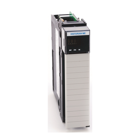
8 FactoryTalk Historian Machine Edition Module Identify FactoryTalk Historian ME Module Components Use the following figures to identify the external features of the FactoryTalk Historian ME Module. FactoryTalk Historian ME Module Front View In the following figure, the FactoryTalk Historian ME Module is shown from the front view with the four-character LED display, LED indicators (BAT, STS, OK), and Ethernet port locations identified. - Page 9 FactoryTalk Historian Machine Edition Module 9 FactoryTalk Historian ME Module Side View In the following figure, the FactoryTalk Historian ME Module is shown from the side view with the backplane and compact flash card slot location identified. All data on the compact flash card is locked to Historian IMPORTANT ME modules.
-
Page 10: Prepare The Chassis For Module Installation
10 FactoryTalk Historian Machine Edition Module Prepare the Chassis for Module Installation Before you install the module, you must install and connect a ControlLogix chassis and power supply. Power Supply For information on installing these products, refer to the publications listed below. -
Page 11: Determine Module Slot Location
FactoryTalk Historian Machine Edition Module 11 Determine Module Slot Location You can install the module in any slot in the ControlLogix chassis. You can have a maximum of two 1756-HIST modules in the same chassis. The figure below shows chassis slot numbering in a 4-slot chassis. Slot 0 is the first slot and is always the leftmost slot in the rack (the first slot to the right of the power supply). -
Page 12: Install The Module In The Chassis
12 FactoryTalk Historian Machine Edition Module Install the Module in the Chassis Align the circuit board with the top and bottom guides in the chassis. Circuit Board Slide the module into the chassis. Make sure the module backplane connector properly connects to the chassis backplane. -
Page 13: Remove Or Replace The Module (When Applicable)
FactoryTalk Historian Machine Edition Module 13 Remove or Replace the Module (when applicable) Push on the upper and lower module tabs to disengage them. Slide the module out of the chassis. If you are replacing an existing module with an identical IMPORTANT one, and you want to resume identical system operation, you must install the new module in the same slot. -
Page 14: Install Or Remove The Module Under Power
Install or Remove the Module Under Power This module is designed to be installed or removed while chassis power is applied. Rockwell Automation recommends that you stop all data collection services before you remove the module. When you insert or remove a module while backplane power is on, an WARNING electrical arc may occur. -
Page 15: Publication 1756-In611A-En-P - February
FactoryTalk Historian Machine Edition Module 15 Connect the Module to the Ethernet Network If you connect or disconnect the Ethernet cable with power applied to this WARNING module or any device on the network, an electrical arc can occur. This could cause an explosion in hazardous location installations. -
Page 16: Apply Chassis Power
16 FactoryTalk Historian Machine Edition Module Apply Chassis Power Check Power Supply and Module Status Check the LED indicators and four-character LED display to determine if the power supply and module are operating properly. Note that it can take up to four to five minutes for the module to become fully operational once power is applied. -
Page 17: Led Indicator Information
FactoryTalk Historian Machine Edition Module 17 LED Indicator Information There are two LED indicators on the front panel of the FactoryTalk Historian ME Module: the three status LED lights and the four-character LED display. These LED indicators determine if the power supply and module are operating properly. -
Page 18: Four-Character Led Display
18 FactoryTalk Historian Machine Edition Module LED light On power-up Status Description Green Module status. Single bi-color red/green LED. Red indicates a major fault has occurred in the module. Green indicates the module is operating normally. Four-character LED Display The four-character LED display provides system status in a static and/or scrolling string on the front panel of the FactoryTalk Historian ME Module. - Page 19 FactoryTalk Historian Machine Edition Module 19 Process or component Four-character display Description Ethernet port LAN OK Displays “LAN OK” if the Ethernet port is configured and the IP address is acquired properly, followed by the IP address. Ethernet port LAN LOST Displays “LAN LOST”...
-
Page 20: Application Status
20 FactoryTalk Historian Machine Edition Module Application Status The Application Status is composed of four application subsystems, as described in the following table. Note: If more than one of the four statuses exist, then they are displayed one after another with a two second duration between each message. Application Subsystem Status Description... - Page 21 FactoryTalk Historian Machine Edition Module 21 Application Subsystem Status Description Data collection status A. collect ok If Data Collection is active and properly B. collect stopped configured, then the “collect ok.” If Data Collection is configured but not active, then the “collect stopped”...
-
Page 22: Port (Ethernet) Led Information
22 FactoryTalk Historian Machine Edition Module Port (Ethernet) LED Information The Port (Ethernet) LED on the 10/100 BASET connector supports IEEE 802.3, has a green LED for link activity, and an amber LED for 10/100 link speed indication. Where to Find Information on Configuring the Module To configure your module, refer to the FactoryTalk Historian ME User’s Guide, publication number 1756-UM611A, available on the FactoryTalk Historian ME Installation CD and online at... - Page 23 FactoryTalk Historian Machine Edition Module 23 – The firmware version number, which is listed on the FactoryTalk Historian ME Module’s home page. Any kind of firmware upgrade or reinstall will clear out IMPORTANT all logs. A firmware upgrade will preseve archived data and application configuration information, but a reinstall will clear out all application configuration information and archived data.
-
Page 24: Specifications
24 FactoryTalk Historian Machine Edition Module Specifications Cat. No. 1756-HIST1G | 1756-HIST2G Environmental Conditions Operating IEC 60068-2-1 (Test Ad, Operating Cold), Temperature IEC 60068-2-2 (Test Bd, Operating Dry Heat), IEC 60068-2-14 (Test Nb, Operating Thermal Shock): 0…60 °C (32…140 °F) Non-operating IEC 60068-2-1 (Test Ab, Unpackaged Non-operating Cold), Temperature... - Page 25 1770-4.1, “Industrial Automation Wiring and Grounding Guidelines”. See the Product Certification link at www.ab.com for Declarations of Conformity, Certificates, and other certification details. Allen-Bradley and ControlLogix are trademarks of Rockwell Automation. Ethernet is a trademark of Digital Equipment Corporation, Intel, and Xerox Corporation. Publication...
- Page 26 Europe/Middle East/Africa: Rockwell Automation SA/NV, Vorstlaan/Boulevard du Souverain 36, 1170 Brussels, Belgium, Tel: (32) 2 663 0600, Fax (32) 2 663 0640 Asia Pacific: Rockwell Automation, Level 14, Core F, Cyberport 3, 100 Cyberport Road, Hong Kong, Tel: (852) 2887 4788, Fax: (852) 2508 1846...
Need help?
Do you have a question about the Allen-Bradley 1756-HIST1G and is the answer not in the manual?
Questions and answers