Sign In
Upload
Download
Table of Contents
Contents
Add to my manuals
Delete from my manuals
Share
URL of this page:
HTML Link:
Bookmark this page
Add
Manual will be automatically added to "My Manuals"
Print this page
×
Bookmark added
×
Added to my manuals
Manuals
Brands
Edwards Manuals
Water Pump
EXS Series
Instruction manual
Edwards EXS Series Instruction Manual
Dry screw vacuum pump
Hide thumbs
1
2
Table Of Contents
3
4
5
6
7
8
9
10
11
12
13
14
15
16
17
18
19
20
21
22
23
24
25
26
27
28
29
30
31
32
33
34
35
36
37
38
39
40
41
42
43
44
45
46
47
48
49
50
51
52
53
54
55
56
57
58
59
60
61
62
63
64
65
66
67
68
69
70
71
72
73
74
75
76
77
78
79
80
page
of
80
Go
/
80
Contents
Table of Contents
Bookmarks
Table of Contents
Table of Contents
Safety and Compliance
Definition of Warnings and Cautions
Trained Personnel
Safety Symbols
Introduction
Scope and Definitions
Applications
Description
Interface Overview
Front View
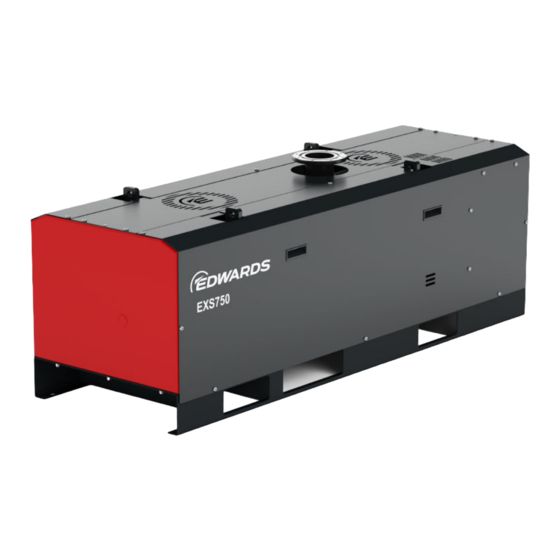
Figure 1 Front View - EXS750
Figure 2 Front View - EXS450
Rear View
Figure 3 Rear View - EXS750
GENIUS Instant Insights (if Fitted)
Figure 4 Rear View - EXS450
Technical Data
General Technical Data
Performance Data
Loading Data
Figure 5 Levelling Foot Loads - EXS750
Figure 6 Levelling Foot Loads - EXS450
Purge Data
Electrical Data
Cooling-Water Data
DP Clean High Flow Purge/Solvent Flush (Option)
Figure 7 Dimension Drawing - EXS750
Figure 8 Dimension Drawing - EXS450
Transportation
Installation
Installation Drawings
Figure 9 Installation Drawing - EXS750
Locate the Dry Pumping System
Figure 10 Installation Drawing - EXS450
Dry Pumping Systems with Optional Castors
Levelling the Pump
Securing the Pump
Piping and Ventilation
Lubrication
Electrical Connections
Figure 11 Service Diagram
Connect the Dry Pumping System to the Vacuum/Exhaust System
Connect the Purge Gas Supply
Figure 12 Connecting the Pump Inlet
Flammable/Pyrophoric Materials
Gas Purges
Leak Test the Dry Pumping System
Electrical Supply
Figure 13 Interspool Connections on the Pump
Mains Supply Cable Connection
EMC Filter
Figure 14 EMC Filter Switch Location
Figure 15 Symmetric Grounding
Connect to the Emergency Stop Circuit
Connect and Set up the Cooling Water
Install the Accessories
Figure 16 Remove the Plastic Plugs from the Water Fittings
Commission the Dry Pumping System
Install Additional Safety Equipment
Purge Gas Set up
High Flow Purge and Solvent Flush Set up
Connecting the Dry Pumping System for Serial Communications
Modbus
Figure 17 DP Clean Assembly for the Pump Only Systems
Operation
Start up
Start, Warm-Up and On-Process Sequences
Dry Pump Speed Control
Manual Shut down
Automatic Shut down
Unplanned Shut down and Alarms
Emergency Stop
Restart the Pump after an Emergency Stop or Automatic Shut down
Dry Pump Clean
High Flow Purge and Solvent Flush
Maintenance
Safety
Preventive Maintenance Schedule
Relocate the Dry Pumping System for Maintenance
Draining the Cooling Water
General Maintenance
Checking the Oil Levels and Refilling
Inspect the Connections, Pipelines, Cables and Fittings
Overhaul
Fault Finding
Inverter Warnings and Alarms
Figure 18 Remove Cubicle Fan
Storage
Disposal
Service
Return the Equipment or Components for Service
Advertisement
Quick Links
1
Table of Contents
2
Technical Data
Download this manual
Dry screw vacuum pump
EXS Series
INSTRUCTION MANUAL
edwardsvacuum.com
A41870880_A
Original instructions
Table of
Contents
Previous
Page
Next
Page
1
2
3
4
5
Advertisement
Table of Contents
Need help?
Do you have a question about the EXS Series and is the answer not in the manual?
Ask a question
Questions and answers
Related Manuals for Edwards EXS Series
Water Pump Edwards EXT70 Instruction Manual
Ext pump accessories (70 pages)
Water Pump Edwards EXT70 Series Instruction Manual
Turbomolecular pumps (42 pages)
Water Pump Edwards EXT70H Series Instruction Manual
Low voltage ext compound molecular pumps (44 pages)
Water Pump Edwards EXT75iDX Instruction Manual
Compound turbomolecular pumps (76 pages)
Water Pump Edwards EXT75DX Instruction Manual
Ext compound turbomolecular pumps (72 pages)
Water Pump Edwards EXT Series Instruction Manual
Compound molecular pump (44 pages)
Water Pump Edwards EXT555H Instruction Manual
Compound turbomolecular pumps (38 pages)
Water Pump Edwards EXT400/200/30H Instruction Manual
Split flow compound turbomolecular vacuum pump (34 pages)
Water Pump Edwards EXT Series Instruction Manual
Compound turbomolecular pumps (40 pages)
Water Pump Edwards EXTPX Series Instruction Manual
Split flow compound turbomolecular vacuum pump (46 pages)
Water Pump Edwards EXPT Instruction Manual
Pumping station (36 pages)
Water Pump Edwards EXT200/200H Instruction Manual
Split flow compound turbomolecular pumps (38 pages)
Water Pump Edwards EXT200/200H LCMS Instruction Manual
Split flow compound turbomolecular pumps (40 pages)
Water Pump Edwards EXT70/70200 Instruction Manual
(26 pages)
Water Pump Edwards EXS750 Instruction Manual
Dry screw vacuum pump (80 pages)
Water Pump Edwards E2M28 Instruction Manual
Rotary pump maintenance kits (24 pages)
This manual is also suitable for:
Exs750
Exs450
Table of Contents
Print
Rename the bookmark
Delete bookmark?
Delete from my manuals?
Login
Sign In
OR
Sign in with Facebook
Sign in with Google
Upload manual
Upload from disk
Upload from URL


Need help?
Do you have a question about the EXS Series and is the answer not in the manual?
Questions and answers