
Related Manuals for Edwards EXPT


Summary of Contents for Edwards EXPT
- Page 1 B723-00-880 Issue C Original Instruction Manual EXPT Pumping Station Description Item Number EXPT Pumping Station B723-00-000...
- Page 2 This page has been intentionally left blank. D of C to be inserted...
-
Page 3: Table Of Contents
Introduction ..................1 Scope and definitions ....................1 Description......................... 2 1.2.1 Overview ........................2 1.2.2 General description of the EXPT pumping station major components ........... 2 1.2.3 Electrical protection ..................... 2 1.2.4 Accessories ........................ 2 Technical data ..................5 General........................5 Electrical data ...................... - Page 4 For return of equipment, complete the HS Forms at the end of this manual. Illustrations Figure Page Components of the EXPT pumping station (typical system shown) ..........3 Equipment dimensions (mm) (XDD1 and EXT75DX shown) ............9 Position the lifting slings/lifting hooks................13 Turbomolecular pump start delay with XDD1 diaphragm pump ..........15 EXPT TIC ........................
- Page 5 B723-00-880 Issue C Associated publications Publication title Publication number EXT Pump Accessories B580-65-880 © Edwards Limited 2009. All rights reserved. Page iii Edwards and the Edwards logo are trademarks of Edwards Limited.
- Page 6 B723-00-880 Issue C This page has been intentionally left blank. Page iv © Edwards Limited 2009. All rights reserved. Edwards and the Edwards logo are trademarks of Edwards Limited.
-
Page 7: Introduction
EXPT Pumping Station. The Supplementary Publications you receive also contain WARNING and CAUTION instructions. When you install and operate the EXPT Pumping Station, you must refer to these Supplementary Publications and obey all of the WARNING and CAUTION instructions which they contain. -
Page 8: Description
1.2.1 Overview The EXPT Pumping Station is a fully automatic pumping system which is suitable for a wide range of applications. The system is capable of utilising an extensive range of standard Edwards backing pumps, turbomolecular pumps and controllers from a single compact unit. The open system configuration allows easy maintenance of the main pumping components. -
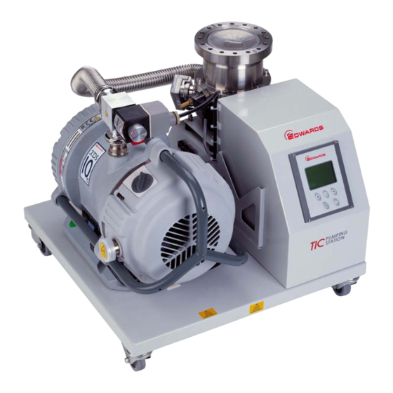
Page 9: Components Of The Expt Pumping Station (Typical System Shown)
B723-00-880 Issue C Figure 1 - Components of the EXPT pumping station (typical system shown) 1. Mains ON/OFF 11. Earth stud 2. Logic interface 12. Heater supply (turbomolecular 3. Serial communications port pump remote use only) 4. Mains input 13. Backing line valve 5. - Page 10 B723-00-880 Issue C This page has been intentionally left blank. Page 4 © Edwards Limited 2009. All rights reserved. Edwards and the Edwards logo are trademarks of Edwards Limited.
-
Page 11: Technical Data
B723-00-880 Issue C Technical data Note: The operating, storage conditions and performance of the EXPT Pumping Station depends on the major components fitted to the EXPT Pumping Station; refer to the technical data in the appropriate supplementary publications. General Dimensions... -
Page 12: Electrical Data
DN100CF 44.25 DN100 ISO-K 43.5 XDS10 DN100CF 45.75 Electrical data Table 3 lists the electrical requirements for the different EXPT Pumping Stations. Table 3 - Electrical data Current (A) Supply voltage Maximum power Backing pump controller 50/60 Hz Full load Start * 4.67... -
Page 13: Legislation And Standards
220-240 5.37 Note: * If the EXPT Pumping Station uses a rotary vane pump, the system may draw up to the start current value shown in Table 3. You must use a slow blow fuse to prevent unnecessary fuse failures, the start current could typically last for several seconds and generally occurs when the rotary vane pump oil is cold. -
Page 14: Earth Stud
Connector type 25-way sub-miniature ‘D’ type socket Power supply 24 V d.c. Serial communications Connector type 9-way sub-miniature ‘D’ type socket Page 8 © Edwards Limited 2009. All rights reserved. Edwards and the Edwards logo are trademarks of Edwards Limited. -
Page 15: Equipment Dimensions (Mm) (Xdd1 And Ext75Dx Shown)
380.0 EXPT2 500.0 ISO63/CF63 415.0 EXT70H NW40 422.0 ISO63 415.0 EXT75DX NW40 427.0 CF63 434.0 ISO100 450.1 EXT255H/ EXT255DX CF100 450.1 © Edwards Limited 2009. All rights reserved. Page 9 Edwards and the Edwards logo are trademarks of Edwards Limited. - Page 16 B723-00-880 Issue C This page has been intentionally left blank. Page 10 © Edwards Limited 2009. All rights reserved. Edwards and the Edwards logo are trademarks of Edwards Limited.
-
Page 17: Installation
Remove the outer cover and all packing materials, remove the protective covers from the inlet and outlet ports, inspect the system for any damage. If the EXPT Pumping Station is damaged, notify your supplier and the carrier in writing within three days; state your order number and invoice number. Retain all packing materials for inspection. -
Page 18: Locate The Expt Pumping Station
If you do not and the turbomolecular pump seizes, movement of the system may damage equipment and injure people. CAUTION When lifting the EXPT Pumping Station, do not attempt to support the mass of the system from the backing pump. CAUTION When lifting the EXPT Pumping Station, always use slings with sufficient length to prevent damage of the system components. -
Page 19: Fill The Rotary Pump With Oil
Fill the rotary pump with oil If the EXPT Pumping Station uses a EM or RV series rotary or rotary vane pump you must fill it with the correct quantity of oil (supplied with the equipment) before you operate the equipment, as described in the pump Instruction Manual. -
Page 20: Connect The Expt Pumping Station To Your Vacuum System
300 mm of the centre line. Note: If the vacuum system is to be supported by the EXPT Pumping Station, the mass of the vacuum system must not be greater than the maximum mass which can be supported by the turbomolecular pump (refer to the EXT Pump Instruction Manual). -
Page 21: Turbomolecular Pump Start Delay With Xdd1 Diaphragm Pump
TIC instruction manual for further details. 3 * If your EXPT Pumping Station uses an XDD1 diaphragm pump, the turbomolecular pump drive will be delayed for two minutes while the backing pump reduces the pressure to a suitable level, this is typical for a five litre volume and will prevent the turbomolecular pump from running under high pressure for a prolonged period. -
Page 22: Commission The Installation
Do not connect Barocel capacitance manometers to the TIC Pumping Station gauge connectors. Doing so will result in damage to the gauge and will invalidate the warranty. Up to three compatible active gauges can be fitted to the gauge connectors on the rear inside of the EXPT Pumping Station housing, refer to Figure 1. -
Page 23: Connecting The Serial Interface
The user serial interface on the rear panel offers the same functionality as the serial interface on the TIC Controller. Refer to the TIC instruction manual for further details of this connector. © Edwards Limited 2009. All rights reserved. Page 17 Edwards and the Edwards logo are trademarks of Edwards Limited. - Page 24 B723-00-880 Issue C This page has been intentionally left blank. Page 18 © Edwards Limited 2009. All rights reserved. Edwards and the Edwards logo are trademarks of Edwards Limited.
-
Page 25: Operation
Start-up Use the following procedure to start the EXPT Pumping Station. If you wish to reconfigure the operation of the EXPT Pumping Station to suit an application, refer to the TIC instruction manual. - Page 26 B723-00-880 Issue C This page has been intentionally left blank. Page 20 © Edwards Limited 2009. All rights reserved. Edwards and the Edwards logo are trademarks of Edwards Limited.
-
Page 27: Maintenance
Do not touch or inhale the thermal breakdown products of fluoroelastomer seals. These breakdown products are very dangerous and may be present if the EXPT Pumping Station has been heated to 260 °C and above. Leak-test the system after maintenance and seal any leaks found if you have disconnected any vacuum or exhaust pipeline connections. -
Page 28: Inspect The Hoses, Pipelines And Connections
Turbo controller (D397-12-880) Turbo instrument controller (D397-22-880) Software updates The software within the Controller and the TIC PC monitor program will be updated as part of Edwards ongoing development program. The updates and associated instruction manual can be found by visiting www.upgrades.edwardsvacuum.com. -
Page 29: Expt Tic Controller Factory Default
B723-00-880 Issue C EXPT TIC controller factory default The EXPT TIC controller has been setup to provide optimum control for your Pumping Cart, however, the default settings can be changed to suit your system control. Note: When performing a software update, the TIC will resume back to its original factory default setting, this is different to the EXPT Pumping Station settings. - Page 30 B723-00-880 Issue C This page has been intentionally left blank. Page 24 © Edwards Limited 2009. All rights reserved. Edwards and the Edwards logo are trademarks of Edwards Limited.
-
Page 31: Storage And Disposal
6. Store the EXPT Pumping Station in cool, dry conditions until required for use. Disposal Dispose of the EXPT Pumping Station and any components safely in accordance with all local and national safety and environmental requirements. Particular care must be taken with components which have been contaminated with dangerous process substances. - Page 32 B723-00-880 Issue C This page has been intentionally left blank. Page 26 © Edwards Limited 2009. All rights reserved. Edwards and the Edwards logo are trademarks of Edwards Limited.
-
Page 33: Spares And Accessories
The majority of these centres employ Service Engineers who have undergone comprehensive Edwards training courses. Order spare parts and accessories from your nearest Edwards company or distributor. When you order, state for each part required: Model and Item Number of your equipment Serial number (if any) Item Number and description of the part. - Page 34 B723-00-880 Issue C This page has been intentionally left blank. Page 28 © Edwards Limited 2009. All rights reserved. Edwards and the Edwards logo are trademarks of Edwards Limited.
-
Page 35: Index
Inspect the hoses, pipelines and connections ..22 Installation ..........11 Legislation and standards ........7 Locate the EXPT pumping station ..... 12 Maintenance ..........21 © Edwards Limited 2009. All rights reserved. Page 29 Edwards and the Edwards logo are trademarks of Edwards Limited. - Page 36 B723-00-880 Issue C This page has been intentionally left blank. Page 30 © Edwards Limited 2009. All rights reserved. Edwards and the Edwards logo are trademarks of Edwards Limited.
Need help?
Do you have a question about the EXPT and is the answer not in the manual?
Questions and answers