Table of Contents
Troubleshooting

Subscribe to Our Youtube Channel
Related Manuals for Omron K7DD


Summary of Contents for Omron K7DD
- Page 1 Overview Procedures Power Line Data Generator Installation and Wiring K7DD Function User's Manual K7DD Support Tool Function Using K7DD Parameters Communications Troubleshooting Appendices INDEX N233-E1-01...
- Page 2 No patent liability is assumed with respect to the use of the information contained herein. Moreover, because OMRON is constantly striving to improve its high-quality products, the information contained in this manual is subject to change without notice. Every precaution has been taken in the preparation of this manual. Nevertheless, OMRON assumes no responsibility for errors or omissions.
- Page 3 Preface Thank you for purchasing a K7DD Power Line Data Generator. This manual describes how to use the K7DD. Read this manual thoroughly and be sure you understand it before attempting to use the K7DD correctly according to the information provided. Keep this manual in a safe place for easy reference.
-
Page 4: Terms And Conditions Agreement
Omron’s exclusive warranty is that the Products will be free from defects in materials and workmanship for a period of twelve months from the date of sale by Omron (or such other period expressed in writing by Omron). Omron disclaims all other warranties, express or implied. -
Page 5: Application Considerations
Disclaimers Performance Data Data presented in Omron Company websites, catalogs and other materials is provided as a guide for the user in determining suitability and does not constitute a warranty. It may represent the result of Omron’s test conditions, and the user must correlate it to actual application requirements. Actual performance is subject to the Omron’s Warranty and Limitations of Liability. -
Page 6: Safety Precautions
Definition of Precautionary Information The following notation is used in this manual to provide precautions required to ensure safe usage of the K7DD Power Line Data Generator. The safety precautions that are provided are extremely important to safety. Always read and heed the information provided in all safety precautions. - Page 7 Safety Precautions CAUTION Minor injury due to electric shock may occasionally occur. Do not touch the Product except for any buttons (keys) while power is being supplied. Electric shock may occasionally occur. Always turn OFF the power supplies to the measured object and the Product before wiring the special CT and voltage input.
- Page 8 Data recovery Backup data and keep the data up-to-date periodically to prepare for data loss. Security Measures of K7DD Support Tool To prevent computer viruses, install antivirus software on a computer where you use this software. Make sure to keep the antivirus software updated.
-
Page 9: Precautions For Safe Use
Precautions for Safe Use Precautions for Safe Use (1) Do not store, install, or use the Product in the following locations: • Outdoor or locations subject to direct sunlight • Locations subject to rain and wind damage • Locations subject to excessive vibration or shock •... -
Page 10: Precautions For Correct Use
(3) Confirm that wire does not stick up after wiring of stranded cable. (4) In crossover wiring, connecting more than one K7DD in parallel may allow a large amount of current to flow. Keep the current to 10 A or less per terminal. -
Page 11: Conformance To Safety Standards
Regulations and Standards (9) Do not install the Product close contact with the heating element. (10) Use a power supply that will reach the rated voltage within 1 second after the power is turned ON. (11) Do not install the Product near equipment that generates high frequencies or surges. (12) Make sure that the setting values registered in the Product match the specifications of the load and special CT that are actually used. - Page 12 Line voltage > 300 ≤ 480 V Rated voltage and size of AWM wires: 600 V min. 1 AWG min. Table 2 Ambient operating temperature Special CT model Wire size of K7DD and special CT K6CM-CICB005-C 55°C max. 24 AWG min. (0.25 mm min.) K6CM-CICB025-C 55°C max.
-
Page 13: Conformance To En/Iec Standards
Regulations and Standards Connection diagrams 3-phase, 3-phase, Single-phase, 4-wire type 3-wire type 2-wire type RS-485 Communications 1 K7DD RS-485 Communications 2 External contact Alarm output 1 ℓ ℓ ℓ Alarm output 2 ℓ ℓ Output at Error ℓ Measurement Category The measurement category classifies the places and equipment which you can connect to the measurement terminals, as prescribed in EN/IEC 61010-2-030. -
Page 14: Terminology
In addition, the parameter that can be accessed only via communications is called a “parameter exclusive to communications.” power ON reset The power ON reset is a reset process inside the K7DD. It can be executed in any of the following ways. • Cycling the power supply •... -
Page 15: Manual Structure
2 Procedures Level 2 heading Level 2 heading Common Settings This section describes common settings for configurations using the K7DD unit only and using K7DD Gives the current Support Tool. heading. (1) Identify Voltage and Current of Actuator and Select Special CT Check the electrical wiring of the actuator to be monitored. -
Page 16: Icons
Precautions on what to do and what not to do to ensure proper operation and performance. Setting-related page In Section 6 Using K7DD Parameters, this indicates the page related to the setting level. Additional information to read as required. This information is provided to increase understanding or make operation easier. -
Page 17: Notation On Main Display And Lvl Display
Manual Structure Notation on Main Display and LVL Display Parameter Display V I P COMM1 COMM2 INTL SCCS RSTR CH Main Display VOLT CRNT FREQ HOLD AGE ALM LVL Display Main Display/Parameter Display The following tables show the correspondence between the symbols displayed on the main display/parameter display and alphabet characters. -
Page 18: Revision History
Revision History Revision History A manual revision code appears as a suffix to the catalog number on the back cover of the manual. N233-E1-01 Revision code Revision code Date Revised content February 2023 Original production Power Line Data Generator User’s Manual (N233) -
Page 19: Sections In This Manual
Sections in this Manual Sections in this Manual Overview Procedures Installation and Wiring K7DD Function Support Tool Function Using K7DD Parameters Communications Troubleshooting Appendices INDEX Power Line Data Generator User’s Manual (N233) -
Page 20: Table Of Contents
Accurate Monitoring with Trigger Settings ....................2-3 Configuration with the K7DD Unit Only................2-4 Flow of Configuration with the K7DD Unit Only ..................2-4 Common Settings ............................. 2-6 (1) Identify Voltage and Current of Actuator and Select Special CT............2-6 (2) Installation and Wiring ......................... - Page 21 (4) Operation Settings for Alarm Output....................2-11 (5) Simplified Threshold Settings (Teaching) ..................2-12 (6-1) Check the Notification Status of the K7DD ..................2-13 (6-2) Check the K7DD Operation after Maintenance ................2-13 Configuration with K7DD Support Tool ................2-14 Flow of Configuration with the K7DD Support Tool................
- Page 22 Section 6 Using K7DD Parameters Levels ............................. 6-2 Setting Parameters and Setting Values ................6-4 6-2-1 Parameter Flow........................... 6-5 Display of Measurement Value Mark ................... 6-6 6-3-1 Feature Value Range for Monitoring ................... 6-7 Monitoring Level........................6-9 6-4-1 Switching Measurement Values and Displayed Channels ............6-9 6-4-2 Parameters on Monitoring Level ....................
- Page 23 A-1-1 K7DD ............................A-2 Ratings and Specifications ........................A-2 Measurement Specifications ........................A-4 Push-In Plus Terminal Blocks Specifications ................... A-5 Specifications of K7DD Support Tool ....................... A-5 A-1-2 Special CTs ..........................A-6 Models..............................A-6 Ratings and Specifications ........................A-6 A-1-3 Applicable Standards ........................
- Page 24 Power Line Data Generator User’s Manual (N233)
- Page 25 This section describes the overview, features, model number legend, part names and functions, internal block diagram, and example configurations for use of the K7DD. 1-1 Outline ............1-2 1-2 Features .
-
Page 26: Outline
Error Detection Mechanism of the K7DD When a rotation mechanism Voltage feature... - Page 27 Highly Accurate Condition Monitoring with the K7DD Support Tool If errors in equipment can be easily reproduced, effects can be inspected visually and quantitatively using the dedicated K7DD Support Tool.
-
Page 28: Features
1 Overview Features The K7DD has three features to accurately detect errors in the rotation mechanism. High-Speed Sensing The Unit can accurately capture the condition of the rotation mechanism by sensing the voltage and current at a high sampling rate of 400 kHz. -
Page 29: Model Number Legend
1 Overview Model Number Legend This section shows the model number legend of the K7DD. K7DD - □□ □ □ (2) (3) (4) Power Meaning Product Base model models supply classification voltage K7DD Power Line Data Generator Voltage and Current... -
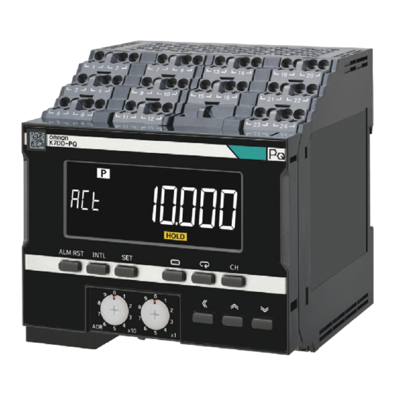
Page 30: Part Names And Functions
1 Overview Part names and functions Appearance Symbol Name Function DIN Track mounting hook Used for mounting to the DIN Track. Only one hook is available on the bottom side. 1 - 6 Power Line Data Generator User’s Manual (N233) - Page 31 1 Overview Front Section AGE ALM Indicators AGE ALM Symbol Name Function Channel • [V] [I] [P]: display Lights according to the feature value displayed in the main display. [V]: R.M.S. voltage, voltage fundamental amplitude, and voltage total harmonic distortion [I]: R.M.S.
- Page 32 1 Overview Symbol Name Function Alarm output Indicates the alarm judgment results in three colors. indicator Green: Normal Yellow: A warning alarm has occurred. Red: A critical alarm has occurred. It will turn red also if any other fatal failure occurs. Status display [INTL]: Collecting abnormal data (Normal data has been acquired) [SCCS]: Valid feature detected.
- Page 33 Name Function Numbers 1 and 2 Operation power Connected with the operation power supply to the K7DD. supply 7 and 8 Trigger input 1 Used to input the trigger signals of measurement start and end. NPN transistor collector: Number 7 terminal...
- Page 34 1 Overview Terminal Symbol Name Function Numbers 25 and 26 Alarm output 1 Compares the measured feature value and the alarm threshold (critical) to produce an alarm output. (Normally close) 27 and 28 Alarm output 2 Compares the measured feature value and the alarm threshold (warming) to produce an alarm output.
-
Page 35: Internal Block Diagram
1 Overview Internal Block Diagram The internal block diagram of the K7DD is shown below. Power Trigger input supply circuit K7DD Power Power transformer transformer Voltage input circuit RS-485 RS-485 communications communications 1 circuit Voltage input circuit RS-485 RS-485 communications... -
Page 36: Example Configurations For Use
Since the K7DD Support Tool employs Modbus-TCP, the communications protocol must be converted. Use a communications converter for connection to the computer. Example Configuration (2) This is a configuration for using the K7DD with a minimum number of devices. If the measured feature value exceeds the Warning... - Page 37 Accurate Monitoring with Trigger Settings ......2-3 2-2 Configuration with the K7DD Unit Only ......2-4 Flow of Configuration with the K7DD Unit Only .
-
Page 38: Overview Of Operating Procedures
Overview of Operating Procedures To Monitor with the K7DD The K7DD measures the feature values of the drive power of a device by selecting and setting the following two items, and detects signs of deterioration of the instrument by capturing changes in these feature values. -
Page 39: Accurate Monitoring With Trigger Settings
2 Procedures Accurate Monitoring with Trigger Settings The K7DD Support Tool allows you to set triggers on the K7DD unit. With trigger settings, you can choose the timing to measure feature values when the rotation mechanism is operating stably, thus enabling more accurate monitoring. -
Page 40: Configuration With The K7Dd Unit Only
Select the special CT to measure the voltage and current of the Actuator and Select Special CT monitored actuator. Install the K7DD and wire for the current and voltage (2) Installation and Wiring measurement. Perform input setting for the K7DD. - Page 41 (6) Monitoring Operation Maintenance implementation (6-2) Check the K7DD Operation after Maintenance Confirm that the K7DD status is normal after maintenance. If the feature value does not drop to normal, there is a possibility that there is another abnormal factor.
-
Page 42: Common Settings
2 Procedures Common Settings This section describes common settings for configurations using the K7DD unit only and using K7DD Support Tool. (1) Identify Voltage and Current of Actuator and Select Special CT Check the electrical wiring of the actuator to be monitored. -
Page 43: Installation And Wiring
Unit to the DIN Track. DIN Track mounting hook Install wiring between the power line to monitor and the K7DD. The following diagram shows the wiring of each connection method. Wiring Example of 3P3W2M Connection (3-phase, 3-wire, 2-watt Meter Method) -
Page 44: Wiring Example Of 3P4W Connection
2 Procedures Wiring Example of 3P4W Connection Install wiring between the Computer monitored 3-phase power (K7DD Support Tool) line and the K7DD by 3-phase, 4-wire type referring to the figure. RS-485 (Modbus RTU) Connect the Communication (1) communications cables of... -
Page 45: Wiring Example Of Single-Phase Current Connection
2 Procedures Wiring Example of Single-phase Current Connection Install wiring between the Computer monitored power line and (K7DD Support Tool) the K7DD by referring to the Single-phase, 2-wire type figure. RS-485 (Modbus RTU) Connect the Communication (1) communications cables of... -
Page 46: Configuration Procedure With The K7Dd Unit Only
2 Procedures Configuration Procedure with the K7DD Unit Only (3) K7DD Input Setting Set the parameters related to Input Setting of K7DD (Initial Setting Level). Configuration with Key Operations Make input settings on the Initial Setting Level. Power ON When you press the Level Key (O) for 3 seconds or more on the Operation Level, you are moved to the Initial Setting Level. -
Page 47: Operation Settings For Alarm Output
2 Procedures (4) Operation Settings for Alarm Output Set the alarm output operation. The following two setting parameters are related Low sensitivity to the alarm output operation. Alarm output at • Alarm Threshold Calculation Sensitivity later timing • Alarm Type Note, however, that the alarm type (Upper limit Threshold of monitored... -
Page 48: Simplified Threshold Settings (Teaching)
If the abnormal data is acquired correctly, [INTL] turns off and [SCCS] lights up. From among several types of features, the K7DD selects the one with significant change as the monitored feature based on the obtained normal and abnormal data, and sets its maximum value as the threshold. -
Page 49: (6-1) Check The Notification Status Of The K7Dd
(4). (6-2) Check the K7DD Operation after Maintenance Confirm that the K7DD status is normal after maintenance. Once the warning or critical status has been checked and the device maintenance has been completed, confirm that the K7DD operates normally. -
Page 50: Configuration With K7Dd Support Tool
Steps (1) and (2) are common to 2-2 Configuration with the K7DD Unit Only and Configuration with K7DD Support Tool. Refer to Common Settings (P.2-6) in the previous section. Install K7DD Support Tool onto the computer before proceeding with configuration. Download the software from the OMRON website. -
Page 51: Settings With Application Setting Flie
2-3-2 To capture sudden errors The K7DD can detect not only feature value anomalies due to equipment deterioration, but also sudden errors in the processing machine, such as blade breakage. The Unit stores internally the maximum or minimum value of the feature values measured in the past. - Page 52 2 Procedures 2 - 16 Power Line Data Generator User’s Manual (N233)
- Page 53 Installation and Wiring This section describes the installation and wiring of the K7DD and special CTs. Be sure to read and understand Precautions for Safe Use (P.-7) before installing and wiring. 3-1 Dimensions ........... 3-2 3-2 Installation .
-
Page 54: Dimensions
3 Installation and Wiring Dimensions K7DD (1.9) (Unit: mm) Special CT (Current Transformer) K6CM-CICB005-C K6CM-CICB025-C K6CM-CICB005 K6CM-CICB025 22.9 28.9 CT through-hole CT through-hole inside diameters inside diameters 25.5 25.3 R7.5 41.3 40.5 (Unit: mm) 3 - 2 Power Line Data Generator User’s Manual (N233) - Page 55 3 Installation and Wiring K6CM-CICB100-C K6CM-CICB200-C K6CM-CICB100 K6CM-CICB200 44.9 29.4 37.4 55.9 CT through-hole inside diameters CT through-hole inside diameters 30.5 35.5 14.5 53.7 14.2 75.7 52.5 K6CM-CICB400-C K6CM-CICB400 62.5 73.5 CT through-hole inside diameters R18.5 35.5 35.5 92.5 (Unit: mm) CT-supplied cable Product side CT side...
-
Page 56: Installation
Installation Orientation Install and use the K7DD with upright installation direction. Installation of End Plates • Install End Plates on the right and left sides of the K7DD. 2) Install an End Plate at each end of the K7DD. 1)... -
Page 57: How To Connect To The Push-In Plus Terminal Blocks
3 Installation and Wiring How to Connect to the Push-In Plus Terminal Blocks Part Names <Upper side> <Lower side> Terminal (insertion) hole Release hole Release hole Terminal (insertion) hole Name Function Terminal (insertion) hole Used to insert wires with ferrules, solid wires, and stranded wires. Release hole Releases the wire when the provided flat-blade screwdriver is inserted. - Page 58 3 Installation and Wiring Checking Connections After the insertion, pull gently on the wire to make sure that it does not come off and that the wire is securely fastened to the terminal block. When you use a stranded wire, make sure that the stranded wire does not bend or touch the adjacent terminal.
- Page 59 0.4×2.5×75 302 Wiha 0.4 mm 2.5 mm AEF.2,5×75 Facom 210-719 Wago SDI 0.4×2.5×75 Weidmuller * You can purchase the SZF 0-0,4×2,5 flat-blade screwdriver made by PHOENIX CONTACT with OMRON model XW4Z-00B. 3 - 7 Power Line Data Generator User’s Manual (N233)
-
Page 60: I/O Wiring
(29), (30): Output at Error Operation Power Supply Terminals The operation power supply terminals are the number 1 and 2 terminals. K7DD There are polarities in the 24 V DC specifications. 3 - 8 Power Line Data Generator User’s Manual (N233) - Page 61 3 Installation and Wiring Trigger Input Terminals The trigger input terminals are the number 7 and K7DD 8 terminals. Internal 5 V Connect the collector to the number 7 terminal Approx. External and the emitter to the number 8 terminal.
- Page 62 The voltage input terminals are the number 13, 14, 15, and 16 terminals. Which terminal is to be connected depends on the ●3-phase 3-wire type of power line. 3P3W2M K7DD Fuse* Fuse* Fuse* ●3-phase 4-wire The R, S, T, and N power lines should be correctly wired to their corresponding terminals.
- Page 63 CT input 1: Number 19 and 20 terminals (CH1) 3P3W2M • CT input 2: Number 21 and 22 terminals (CH2) K7DD • CT input 3: Number 23 and 24 terminals (CH3) Which terminal is to be connected depends on the type of power line.
- Page 64 All the special CTs connected to one unit of K7DD must have the same Load side ratings. • Make sure that the special CT settings on the K7DD match the ratings of the special CTs to be used. Power Split/fastening supply side hook •...
-
Page 65: Wiring To The Power Lines
3 Installation and Wiring Wiring to the Power Lines This section describes the wiring of the power lines that enable the K7DD to measure. For Single-Phase AC Single-Phase Current Connect a single special CT, and connect it to the number 19 and 20 terminals of the K7DD. -
Page 66: Wiring The Communications Cables
Example of Connection to K7DD Support Tool The communications cables are used to make initial settings of the K7DD with the K7DD Support Tool. Use the number 3 and 4 (communications 1 terminals) of the Push-In Plus terminal block. - Page 67 3 Installation and Wiring The data length and stop bits of the communications protocol Modbus RTU for the K7DD are fixed internally. • Data Length: Always 8 bits • Stop Bits: Always 1 bit (with Even or Odd parity) Always 2 bits (with None parity) Make sure that both the K7DD and the communications converter have the same RS-485 (Modbus RTU) communications settings (baud rate, data length, stop bits, and parity).
-
Page 68: Setting The Unit Number
Set the following addresses for communications settings with the K7DD Support Tool. IP address: IP address of the communications converter Slave address: Unit number of the K7DD The default values of the communications settings on the K7DD (Modbus RTU) are as follows. These values are used for explanation. • Baud Rate: 115.2 kbps... - Page 69 4-1 K7DD Functions ........
-
Page 70: K7Dd Functions
• R.M.S. Voltage Out-of-Range Error [VOLT] • R.M.S. Current Out-of-Range Error [CRNT] • Frequency Out-of-Range Error [FREQ] Self-diagnosis Error This function notifies you when the K7DD is unable to perform its intended -4-6 functions. 4 - 2 Power Line Data Generator User’s Manual (N233) -
Page 71: Feature Measurement
4 K7DD Function Feature Measurement In order to determine how much the target device has deteriorated, the K7DD calculates 142 types of feature values based on the current and voltage, and records them as measurement values. The K7DD unit can monitor 9 types of feature values. The Support Tool can monitor the measurement results of all feature values. -
Page 72: Simplified Threshold Settings
4 K7DD Function Simplified Threshold Settings 4-3-1 Overview In order to detect a deterioration error that always appears, the simplified threshold setting function automatically selects feature values and sets thresholds based on the data from the teaching performed until an error actually occurs. -
Page 73: Conditions To Use
Conditions to Use The conditions to use are as follows: • The user can operate the K7DD while the device is in operation. • Normal average value can be obtained under the condition that the product is considered to be normal, such as immediately after maintenance/inspection or when it is brand new. -
Page 74: Description Of Operation
Description of Operation The operation of the simplified threshold setting is explained in the figure below. This assumes that the K7DD input settings have been completed. Refer to 2-2 Configuration with the K7DD Unit Only (P.2-4) for input setting procedures. - Page 75 14!4 a period longer than the feature value calculation cycle is required. Inside K7DD, the average value data for the feature calculation cycle is always calculated. Therefore, if there is a power failure during this period, start teaching after the time for the feature calculation cycle has elapsed.
- Page 76 4 K7DD Function Feature Values to Be Selected The feature values to be selected for monitoring by the simplified threshold setting function are the following 5 types among the 9 types displayed at the Monitoring Level. • R.M.S. Voltage •...
-
Page 77: Alarm
4 K7DD Function Alarm The alarm function of the K7DD detects and notifies you when a monitored feature falls into the alarm range determined by the critical/warning thresholds. The parameters related to the alarm function are as follows: Parameter Description Alarm type This is the parameter that can be set in the Support Tool. -
Page 78: Releasing The Alarm Latch
Procedure for Moving from Level to Level (P.6-3) in 6-1 Levels for details. 4-4-3 Alarm Types The K7DD allows you to set two alarm types. The settings are available from the Support Tool or via communications. Feature value Type Description of operation... -
Page 79: Measurement Error
4 K7DD Function Measurement Error The measurement error is a function to notify you that the service condition needs adjusting and improving to monitor the power condition. The details of measurement errors are given in the following table. Measurement error type... - Page 80 4 K7DD Function Occurrence Conditions and Reset Conditions for Measurement Errors This section shows the types of measurement errors and the error occurrence/reset conditions. Error type Error occurrence condition Error reset condition Voltage Value Out-of-Range Error The voltage value went out of the The voltage value went into the range.
-
Page 81: Self-Diagnosis Error
The self-diagnosis error is an abnormal state in which the K7DD cannot perform the functions that it was primarily meant to perform. An error has occurred in the internal memory operation. If the self-diagnosis error has occurred in the K7DD, it will behave in one of the following two patterns. Pattern 1 •... - Page 82 4 K7DD Function 4 - 14 Power Line Data Generator User’s Manual (N233)
- Page 83 Support Tool Function The functions of the K7DD are separately described in Chapter 4 K7DD Function, and Chapter 5 Support Tool Function. This section describes the support tools for the K7DD, including all feature measurement functions, feature selection support/alarm threshold setting support functions, state diagnosis, and arrival prediction function.
-
Page 84: Support Tool Functions
5 Support Tool Function Support Tool Functions The functions of the K7DD Support Tool are given in the following table. Function name Description Ref. All feature measurement The K7DD can monitor 9 types of feature values on its display. -5-1 and trigger measurement In the Support Tool, all 142 types of feature values can be monitored. -
Page 85: All Feature Measurement And Trigger Measurement Simulation
The Support Tool can monitor the measurement results of all feature values. The feature values that can be checked in the K7DD Support Tool are as shown in the table below. The shaded areas in the table indicate feature values used in the Support Tool. - Page 86 5 Support Tool Function Monitorable wiring state Feature Tool Description Unit 3P3W2M Single phase value display 3P4W current 1.5th order The waveform of 1.5 times the frequency of the harmonic fundamental frequency (power frequency) is called current the 1.5th order harmonic current. Observing this value allows for identifying the ratio of harmonic components included for each order.
-
Page 87: Trigger Measurement Simulation
5-2-2 Trigger Measurement Simulation The Support Tool allows you to configure trigger settings on the K7DD. Triggers can be used to set the timing of feature measurement of the K7DD, enabling accurate condition monitoring. Hovering the mouse over i on the window displays tips and explanations. Perform settings according to the instructions. -
Page 88: Abnormal Data Registration
Method A: Machine Condition Data (Abnormal)...The data measured by actually generating an error is used as abnormal data. Method B: Application Setting File...The data validated by OMRON beforehand is used as abnormal data. Method C: Values Memorized in Monitoring Device...The data of the maximum/minimum value of each feature recorded by the K7DD monitoring operation is used as abnormal data. -
Page 89: Feature Selection Support/Alarm Threshold Setting Support
"Application Setting Flie" is available for registering abnormal data. An application configuration file contains feature values and alarm threshold setting information for specific application errors that have been validated by OMRON beforehand. You can select feature values and set alarm thresholds without reproducing any errors. -
Page 90: Digital Maintenance Log/ Arrival Prediction
5 Support Tool Function Digital Maintenance Log/ Arrival Prediction K7DD Support Tool allows you to record data acquired from the K7DD and to perform analysis, such as predicting the occurrence of errors. Digital Maintenance Log: You can keep a maintenance record by estimating the progress of an... - Page 91 Using K7DD Parameters This section describes how to use the K7DD parameters. 6-1 Levels ............6-2 6-2 Setting Parameters and Setting Values .
-
Page 92: Levels
6 Using K7DD Parameters Levels The setting parameters are grouped into “levels.” Levels are divided into four types for the K7DD. Measurement Level Description operation Monitoring Possible This is a level on which to monitor measurement values. The Unit is on this level immediately after the power is turned ON. - Page 93 6 Using K7DD Parameters Procedure for Moving from Level to Level To Adjustment Level Power ON Pressing the Level Key (O) on the Monitoring Level (for less than 1 second) moves you to the Adjustment Level. Power ON reset At least 1 s ...
-
Page 94: Setting Parameters And Setting Values
6 Using K7DD Parameters Setting Parameters and Setting Values Setting parameters The setting items on each level are called “setting parameters.” The setting parameters can be switched over with the Mode Key (M). The setting parameters can be switched over among CH1, CH2, and CH3 with the Channel Key (U). -
Page 95: Parameter Flow
6 Using K7DD Parameters 6-2-1 Parameter Flow Power ON Power ON reset At least 1 s At least 1 s Adjustment Level Monitoring Level Initial Setting Level Communications Level LVL a LVL 0 LVL 1 Less Less Ch1 to 3 ver ... -
Page 96: Display Of Measurement Value Mark
6 Using K7DD Parameters Display of Measurement Value Mark The measurement value display (a) and (b) indicate the following marks according to the wiring state. Feature Displayed channel Wiring state value AGE ALM system Voltage system 3-phase Dis- 3-wire Meaning... -
Page 97: Feature Value Range For Monitoring
Feature Value Range for Monitoring The following table lists the range of feature values displayed on the Monitoring Level and Adjustment Level. The shaded areas in the table indicate feature values used in the K7DD Support Tool. Monitoring range *1... - Page 98 6 Using K7DD Parameters Monitoring range *1 Feature value Range condition Unit Min. Max. 0.5th order harmonic current 100.0 1.5th order harmonic current Same as above. Same as Same as Same as above. above. above. 2nd order harmonic current 62.5th order harmonic current...
-
Page 99: Monitoring Level
6 Using K7DD Parameters Monitoring Level The Monitoring Level is a level on which to display the values that the K7DD measured. Turning ON the power executes Monitoring Level (lvl0) the power ON reset process to move you to the Monitoring Level. -
Page 100: Parameters On Monitoring Level
6 Using K7DD Parameters 6-4-2 Parameters on Monitoring Level The parameters on the Monitoring Level display the following values. R.M.S. Voltage This is the R.M.S. voltage of measured signals. Range Monitoring range The monitoring range varies depending on the voltage input range. - Page 101 6 Using K7DD Parameters R.M.S. Current This is the R.M.S. current of measured signals. Range Monitoring range The monitoring range varies depending on the current input range. 0.000 to 5.500 (A) 25 A 0.0 to 27.5 (A) 100 A 0.0 to 110.0 (A) 200 A 0.0 to 220.0 (A)
- Page 102 5A, (kW) (3-phase, 3-wire, 2-watt Meter Method) (P.2-7), Wiring Example of All voltages 3P4W Connection (P.2-8) in 2-2 Configuration with the K7DD Unit Only for details. Setting-related page 4-2 Feature Measurement (P. 4-3) 4-3 Simplified Threshold Settings (P. 4-4) Power Factor This is the power factor of measured signals.
-
Page 103: Adjustment Level (Lvl A)
6 Using K7DD Parameters Adjustment Level (LVL a) The Adjustment Level is a level that has the parameters required to be adjusted for using the K7DD. Pressing the Level Key (O) on Adjustment Level (lvla) the Monitoring Level (for less than... -
Page 104: Setting Parameters On Adjustment Level
For the setting range, refer to A-2 Parameters List (P.A-9). Product Version This parameter displays the product version of the K7DD. rms .[ R.M.S. Voltage Critical Threshold Set the alarm threshold (critical) for the R.M.S. voltage of the... - Page 105 6 Using K7DD Parameters fnd .[ Voltage Fundamental Amplitude Critical Threshold Set the alarm threshold (critical) for the voltage fundamental Valid setting Range amplitude of the measurement target. range The alarm will be turned ON if the voltage fundamental amplitude 150 V 0.0 to 233.4 (V)
- Page 106 6 Using K7DD Parameters thd .{ Voltage Total Harmonic Distortion Warning Threshold Set the alarm threshold (warning) for the voltage total harmonic Valid setting Range distortion of the measurement target. range The alarm will be turned ON if the voltage total harmonic distortion 0.0 to 100.0 (%)
- Page 107 6 Using K7DD Parameters fnd .[ Current Fundamental Amplitude Critical Threshold Set the alarm threshold (critical) for the fundamental amplitude of Valid setting Range the measurement target. range The alarm will be turned ON if the fundamental amplitude exceeds 0.000 to 7.779 (A) this threshold (critical).
- Page 108 6 Using K7DD Parameters thd .{ Voltage Total Harmonic Distortion Warning Threshold Set the alarm threshold (warning) for the current total harmonic Valid setting Range distortion of the measurement target. range The alarm will be turned ON if the current total harmonic distortion 0.0 to 100.0 (%)
- Page 109 6 Using K7DD Parameters pf .[ Power Factor Critical Threshold Set the alarm threshold (critical) for the power factor of the Valid setting Range measurement target. range The alarm will be turned ON if the power factor exceeds this -1.00 to 1.00 (-) threshold (critical).
-
Page 110: Initial Setting Level (Lvl 0)
6 Using K7DD Parameters Initial Setting Level (LVL 0) The Initial Setting Level is a level that has the parameters required to Initial Setting Level (lvl0) be set first for using the K7DD. wrng Wiring State Current Input i-in Range... -
Page 111: Parameters On Initial Setting Level
3P3W2M (3-phase 3-wire) 3P4W (3-phase 4-wire) Single-phase current only Setting-related page (3) K7DD Input Setting (P. 2-10) of 2-2 Configuration with the K7DD Unit Only 6-3 Display of Measurement Value Mark (P. 6-6) i-in Current Input Range Set the current input range. - Page 112 Refer to 4-3-2 Conditions to Use (P.4-5) for details. Setting-related page (3) K7DD Input Setting (P. 2-10) of 2-2 Configuration with the K7DD Unit Only 4-3 Simplified Threshold Settings (P. 4-4) acof Alarm Threshold Calculation Sensitivity Set the alarm threshold calculation sensitivity.
-
Page 113: Communications Setting Level (Lvl 1)
Communications Setting Level (LVL 1) The Communications Setting Level is a level where you set the Communications Setting Level (lvl1) parameters required for serial communications (Modbus RTU) between the K7DD and external devices. bps1 Baud Rate 1 pty1 Parity 1... -
Page 114: Setting Parameters On Communications Setting Level
0 to 99 (ms) 20 (ms) This is a wait time from when the K7DD receives a command from the host system until it returns a response. If the response comes so fast that the host system cannot receive it properly, increase this setting value. -
Page 115: Operation Command With Key Operation
6 Using K7DD Parameters Operation Command with Key Operation The following Operation Commands can be executed with key operations on the K7DD. Operation Command Description Normal Data Acquisition Starts or cancels the acquisition of normal data. Command Abnormal Data Acquisition Terminates the acquisition of abnormal data. - Page 116 6 Using K7DD Parameters Alarm Latch Cancel Command Procedure Press the [ALM RST] key for 3 seconds or more on the Monitoring Level or Adjustment Level. The parameter display starts to flash at high speed. After 3 seconds have elapsed, the alarm latch is released for all channels.
- Page 117 K7DD Information Area ........
-
Page 118: Communications
RS-485 communications 2 terminal communications 1 and RS-485 communications 2. These ports are used to connect the K7DD Support Tool or host system, such as PLC. When using these ports, use the RS-485 communications 1 first. 7 - 2 Power Line Data Generator User’s Manual (N233) -
Page 119: Communications Overview
No.02 No.03 The host system (master) sends a command Host system Command frame Command frame frame, and the K7DD (slave) returns a response frame corresponding to the command. One K7DD Response frame command frame is paired with one response frame. - Page 120 7 Communications Types of Communications Commands The following three types of communications commands are available for the K7DD. Communications command Description Read Variable Area Reads the variable area. Write Variable Area Writes the variable area. Operation Command Executes the following operations for the K7DD.
-
Page 121: To Monitor All Feature Values Together (Read Variable Area)
Refer to 7-7 Variable Area Map (P.7-17) for details on the variable area to specify. The setting parameters can be read regardless of the status of the K7DD. The reading operation does not affect the K7DD operation. 7 - 5... -
Page 122: Changing Setting Parameters (Write Variable Area)
The Write Variable Area Command allows you to change the setting parameters. With the Write Variable Area Command, the Host system K7DD can write addresses by specifying them one by one or multiple addresses together by Writing to variable Write Normal area H’0100 to... -
Page 123: Operation Command
This command executes the power ON reset process, as with a reset process that runs when the power turns ON. The power ON reset process puts the K7DD in the same initial state as after the power is turned ON. The Software Reset Command can be accepted on any levels. - Page 124 7 Communications Operation Stop State Transition Command This command moves you to the Initial Setting Level where operations are stopped and can be accepted on the Operation Level or Adjustment Level where operations are performed. In order to set the setting values on the Initial Setting Level or Communications Setting Level, you need to enter the operation stopped state.
-
Page 125: Modbus Rtu Communications Format
Silent interval of 3.5 character times minimum. Slave address A number used to identify a destination device. Specify the unit number of the K7DD. The unit number can be set between H’01 to H’63 hexadecimal (01 to 99 decimal). To broadcast this value, specify H’00. However, in the case of broadcasting, no response is returned. - Page 126 7 Communications (6) CRC processing continues to the end of the message, as XOR operations are performed on the content of the CRC register and the next byte of the message, and step (3) is repeated. The result is returned to the CRC register. (7) The result of the CRC calculation (value in the CRC register) is appended to the last byte of the message.
- Page 127 7 Communications Error Code: Completion Name Description code H’01 Function code error An unsupported function code was received. H’02 Variable address error The variable address was accessed in excess of H’FFFF. H’03 Variable data error • The number of elements specified in the command frame data and the number of data do not match.
-
Page 128: Read Variable Area Command
CRC-16 calculation range Slave address A number used to identify a destination device. Specify the unit number of the K7DD. The unit number can be set between H’01 to H’63 hexadecimal (01 to 99 decimal). Function code The Read Variable Area Command's function code is H’03. -
Page 129: Write Variable Area Command
2 bytes CRC-16 calculation range Slave address A number used to identify a destination device. Specify the unit number of the K7DD. The unit number can be set between H’01 to H’63 hexadecimal (01 to 99 decimal). Function code The Write Variable Area Command's function code is H’10. - Page 130 7 Communications Response Codes: Function code Error code Error name Description H’10 Normal end The command ended normally. Variable address The variable address was accessed in excess of H’02 error H’FFFF. • The number of data does not match the number of elements.
-
Page 131: Operation Command Or Write Variable Area Command (Single)
CRC-16 calculation range Slave address A number used to identify a destination device. Specify the unit number of the K7DD. The unit number can be set between H’00 to H’63 hexadecimal (0 to 99 decimal). Function code The function code of Operation Command or Write Variable Area Command (single) is H’06. - Page 132 7 Communications Response Frame: When the command is executed successfully, the response returns the same data sent in the command frame. Response Codes: Function Error Error name Description code code H’06 Normal end The command ended normally. H’86 H’03 Variable address The write data is out of the setting range.
-
Page 133: Variable Area Map
7 Communications Variable Area Map 7-7-1 Variable Area Map Descriptions Since the K7DD can monitor 3 channels, variable addresses are also provided for 3 channels. Hexadecimal values are expressed by H’**. • The variable addresses of CH1 start with Example: H’1000. - Page 134 • • The variable addresses of CH1, CH2, and CH3 Example: start with H’0000. Variable Channel Variable name address Common H'0000 K7DD Status to CH1, H’0001 to Reserved CH2, and H’0070 H’0080 Monitored Feature [0] Monitor H’0081 Ch 1 H’0082...
-
Page 135: Common Variable Area
H’0000 K7DD Status This is a monitored value. It is the parameter exclusive to communications. It is the data that brings together the status of the K7DD. Refer to 7-7-5 Details about Status Information (P.7-25) for details about the bits. - Page 136 H’0000: 0 to 150 V (default value), H’0001: 0 to 300 V, restart H’0002: 0 to 600 V H’0304 Feature Calculation Cycle This is a setting parameter. It is a cycle at which the K7DD After calculates the feature values. Set the parameter according restart to the device operation.
- Page 137 7 Communications Setting Variable Variable name Description reflection address timing H’0400 Trigger Mode *1 This is a setting parameter. Set the mode of the trigger. After H'0000: Continuous (default value), H'0001: External, restart H'0002: Internal H’0401 Trigger Type *1 This is a setting parameter. Set the type of the trigger. After H'0000: Rising (default value), H'0001: Falling, H'0002: restart...
- Page 138 7 Communications Setting Variable Variable name Description reflection address timing H'0700 Monitored Feature [0] Setting This is a setting parameter. It is the ID of the feature value After H'0701 Monitored Feature [1] Setting to be monitored, specified among a number of features. restart 13 types are allocated for each channel.
-
Page 139: Variable Area For Each Channel
7 Communications 7-7-3 Variable Area for Each Channel This manual describes only the variable addresses of CH1 so as to simplify the description. When you use a variable address of CH2, change the beginning of the variable address of CH1 into 3 or 4 before use. -
Page 140: K7Dd Information Area
4549734776646: K7DD-PQMA 4549734776653: K7DD-PQMD Example: When the code is read for the K7DD, it becomes H’0XXXXXXXXXXXXX00, with H’0 appended to the most-significant digit and H’00 appended to the least-significant digit. Variable address H’C01A is the most-significant digit and H’C01D is the least-significant digit. -
Page 141: Details About Status Information
Input Circuit occur Error *1 1: Input Circuit Error occurred. Not used: Always 0 *1 When this bit is 1, an error has occurred in the K7DD. Refer to Section 8 Troubleshooting (P. 8-1) for details. Variable Variable Bit name Description... - Page 142 7 Communications Variable Variable Bit name Description address name H’1001 Monitoring 0: Deterioration Alarm Deterioration Status (Warning) did not occur Alarm 1: Deterioration Alarm (Warning) (Warning) occurred 0: Deterioration Alarm Deterioration (Critical) did not occur Alarm 1: Deterioration Alarm (Critical) (Critical) occurred Not used: Always 0 7 - 26...
-
Page 143: Troubleshooting
Troubleshooting 8-1 Troubleshooting ..........8-2 8 - 1 Power Line Data Generator User’s Manual (N233) - Page 144 8 Troubleshooting Troubleshooting Check the following table if the K7DD does not perform the expected operation. When Problems Cause Possible correction Remarks When the power is turned The frequency may not be Check the wiring of the CTs. 3-4 I/O Wiring (P.3-8)
- Page 145 K7DD ........
-
Page 146: A-1 Specifications
Operating frequency 45 to 65 Hz range Power consumption K7DD-PQMA: 15.7 VA max. (100 to 240 V AC) K7DD-PQMD: 5.2 W max. (24 V DC) Recommend external fuse T2A, time delay, high-breaking capacity CH1 voltage input Measurement accuracy A-4 Feature Calculations (P.A-13) - Page 147 A Appendices Item Specifications Transistor Contact form NPN open-collector output Rated voltage 24 V DC (maximum voltage: 26.4 V DC) (Alarm output, Maximum current 50 mA Output at Error) Leakage current at 0.1 mA max. power OFF Residual voltage 1.5 V max. Ambient operating temperature -10 to 55°C (with no condensation or icing) Ambient operating humidity...
-
Page 148: Measurement Specifications
A Appendices Measurement Specifications Item Specifications Conditions Input range Current range: 0.275 to 5.5 A • Defined by R.M.S. values using a (Displayable range) 25 A range: 1.375 to 27.5 A sine wave. • The power frequency must be within 100 A range: 5.5 to 110.0 A 200 A range: 11.0 to 220.0 A the acceptable range. -
Page 149: Push-In Plus Terminal Blocks Specifications
Recommended crimp tool CRIMPFOX6 PZ6 roto Variocrimp4 CRIMPFOX6T-F CRIMPFOX10S Specifications of K7DD Support Tool • System requirements Supported OS Windows10 (Version 1607 or later)/11 (English or Japanese) 32-bit (Windows10 only)/64-bit edition Computer specifications CPU: 32-bit or 64 bit processor of 1 GHz or faster... -
Page 150: A-1-2 Special Cts
Supplied cable length 2.9 m Supplied cable terminal K7DD side: Ferrule, CT side: Round crimp terminal Degree of protection IP20 *1 To comply with UL certification for the special CT, refer to Conformance to Safety Standards (P.-9). - Page 151 A Appendices The frequency characteristics of CTs are as follows: K6CM-CICB005-C K6CM-CICB025-C K6CM-CICB005 K6CM-CICB025 1.00% 1.00% 0.50% 0.50% 10 A 0.00% 0.00% 15 A 20 A -0.50% 25 A -0.50% -1.00% -1.00% Frequency [Hz] Frequency [Hz] K6CM-CICB100-C K6CM-CICB200-C K6CM-CICB100 K6CM-CICB200 1.00% 1.00% 0.50%...
-
Page 152: A-1-3 Applicable Standards
A Appendices A-1-3 Applicable Standards Applicable standards Details Installation Pollution Degree 2, Overvoltage category II, UKCA environment Measurement category II, III *1 Based on EN 61010-1 and EN61010-2-030 EN 61326-1 EMI: Class A, EMS: Industrial environments UL (North America) UL 61010-1, CAN/CSA C22.2 No. 61010-1 Pollution Degree 2, Overvoltage category UL 61010-2-030, CAN/CSA C22.2 No. -
Page 153: A-2 Parameters List
A Appendices A-2 Parameters List This section shows the parameters to be displayed on the main display of the K7DD. Refer to 7-7 Variable Area Map (P.7-17) for parameters exclusive to communications. Type and Level Parameter name Setting (monitoring) range... - Page 154 A Appendices Type and Level Parameter name Setting (monitoring) range Default value characters -3276.1 to 3276.1 (V) 3276.1 (V) Adjustment Voltage fnd .{ Fundamental Amplitude Warning Threshold Voltage Total -3276.1 to 3276.1 (%) 3276.1(%) thd .[ Harmonic Distortion Critical Threshold Voltage Total -3276.1 to 3276.1 (%) 3276.1(%) thd .{...
- Page 155 A Appendices Type and Level Parameter name Setting (monitoring) range Default value characters Adjustment Power Factor -327.61 to 327.61 327.61 pf .[ Critical Threshold Power Factor -327.61 to 327.61 327.61 pf .{ Warning Threshold Power Frequency -3276.1 to 3276.1 (Hz) 3276.1 (Hz) freq.[ Critical Threshold Power Frequency...
-
Page 156: A-3 Parameter Flow
A Appendices A-3 Parameter Flow This section shows the parameters displayed on the main display of the K7DD. Refer to 7-7 Variable Area Map (P.7-17) for parameters exclusive to communications. Power ON Power ON reset At least 1 s At least 1 s... -
Page 157: A-4 Feature Calculations
A Appendices A-4 Feature Calculations This section provides the mathematical equations for the feature values calculated by the K7DD. A-4-1 Feature Values of Voltage System Wiring state Feature 3P3W2M 3P4W Σ RMS(12) (12)s − V (12)s (1)s (2)s Σ Σ... - Page 158 A Appendices Wiring state Feature 3P3W2M 3P4W 1 − 3 - 6β × 100 [%] Unb = 1 + 3 - 6β + V1 + V1 (12) (23) (31) , V1 , V1 β Fundamental wave of (12) (23) (31) +...
-
Page 159: A-4-2 Feature Values Of Current System
A Appendices A-4-2 Feature Values of Current System Wiring state Feature 3P3W2M 3P4W Single phase current RMS(1) Σ (1)s RMS(c) RMS(c) RMS(2) Σ Σ Σ (c)s (c)s R.M.S. current − I − I (1)s (2)s c : Measuring channel (1 to 3) c : Measuring channel (1) s : Sampling point s : Sampling point... - Page 160 A Appendices Wiring state Feature 3P3W2M 3P4W Single phase current Current Primary harmonics Primary harmonics (fundamental wave) fundamental (fundamental wave) when calculating harmonics when calculating harmonics amplitude c : Measuring channel (1 to 3) c : Measuring channel (1) 0.5th order harmonic ×...
-
Page 161: Feature Values Of Power Consumption, Power Factor And Power Frequency
A Appendices A-4-3 Feature Values of Power Consumption, Power Factor and Power Frequency Wiring state Single Feature 3P3W2M 3P4W phase current P = P + P + P Σ Σ P = P + P × I × I + (1)s (1)s (2)s... - Page 162 A Appendices A - 18 Power Line Data Generator User’s Manual (N233)
- Page 163 INDEX I - 1 Power Line Data Generator User’s Manual (N233)
- Page 164 (1) ..........1-12 ambient operating humidity ..........A-3 example configuration (2) ..........1-12 ambient operating temperature ........A-3 example of connection to k7dd software tool ....3-14 appearance ..............1-6 exterior color ..............A-3 applicable standards ............A-8 applicable wire size ............A-5 applicable wires ..............A-5...
- Page 165 Internal Trigger Source ..........7-21 parameter flow ............6-5, A-12 parity ................A-2 Parity 1 ..............7-21, A-11 Parity 2 ..............7-21, A-11 K7DD Status ..............7-19 % FS ................12 power consumption ............A-2 Power Factor ..............A-9 Power Factor Critical Threshold ........A-11 leakage current when power turning OFF ......
- Page 166 (without ferrules) ........A-3 switching displayed channels ........6-4, 6-9 terminal block type ............A-3 terminal section .............. 1-9 To Monitor with the K7DD ..........2-2 transistor output terminals ..........3-12 transmission path connection method ......A-2 trigger input terminals ............. 3-9 Trigger Mode ..............
- Page 167 I - 5 Power Line Data Generator User’s Manual (N233)
- Page 168 I - 6 Power Line Data Generator User’s Manual (N233)
- Page 169 Fax: (31) 2356-81-388 Tel: (1) 847-843-7900 Fax: (1) 847-843-7787 ©OMRON Corporation 2023 All Rights Reserved. OMRON ASIA PACIFIC PTE. LTD. OMRON (CHINA) CO., LTD. In the interest of product improvement, 438B Alexandra Road, #08-01/02 Alexandra Room 2211, Bank of China Tower, specifications are subject to change without notice.
Need help?
Do you have a question about the K7DD and is the answer not in the manual?
Questions and answers