Omron K3HB Applications Manual
Hide thumbs
Also See for K3HB:
- Manual (147 pages) ,
- Datasheet (33 pages) ,
- Technical communications user's manual (147 pages)
Table of Contents
Advertisement
Quick Links
Advertisement
Chapters
Table of Contents

Related Manuals for Omron K3HB


Summary of Contents for Omron K3HB
- Page 1 Cat. No. N110-E1-02 K3HB APPLICATION MANUAL...
- Page 2 Preface This manual describes the application methods for the K3HB. Please read this manual before attempting to use the K3HB to ensure that you are using the K3HB correctly. Keep this manual in a safe location so that it is available for reference when required.
- Page 3 ● Definition of Safety Notices and Information The following notation is used in this manual to provide precautions required to ensure safe usage of the K3HB. The safety precautions that are provided are extremely important to safety. Always read and heed the information provided in all safety precautions.
- Page 4 ● Precautions CAUTION Do not touch the terminals while power is being supplied. Doing so may result in electric shock. Do not disassemble the product or touch internal parts while power is being supplied. Doing so may result in electric shock, fire, or malfunction. Perform correct setting of the product according to the application.
- Page 5 General Precautions ● Observe the following precautions to ensure safety. (1) Be sure to confirm the name and polarity for each terminal before performing wiring. Incorrect wiring may result in burning of or other damage to internal components. (2) Use a power supply within the specified voltage range. Use the product within the rated load.
- Page 6 ● Noise Countermeasures Do not install the product near devices generating strong high-frequency waves or surges, such as high-frequency welding and sewing machines. (1) Mount a surge suppressor or noise filter to peripheral devices generating noise, in particular, motors, transformers, solenoids, and magnet coils. Line filter Linear Sensor Indicator...
- Page 7 ● Extending Product Life (1) Do not use the product in locations subject to temperatures or humidity levels outside the specified ranges or in locations prone to condensation. If the product is installed in a panel, ensure that the temperature around the product (not the temperature around the panel) does not go outside the specified range.
- Page 8 ● Revision History The revision code of this manual is given at the end of the catalog number at the bottom left of the back cover. Cat. No. N110-E1-02 Revision Date Pages and changes code March Original production 2003 Page 1-2: Changed “High-pass filter” to “Previous Average Comparison”. September Page 5-16: Added a conditional statement to the Remarks.
- Page 9 About this Manual Manual Structure Preface Provides precautionary information, a manual revision history, an overview of the manual contents, information on using this manual, and other general information. Section 1 Outline Provides an overview and describes the features of the product. Section 2 Preparations Describes the mounting and wiring required before using the product.
- Page 10 ● Settings data notation The letters of the alphabet in settings data are displayed as shown below.
- Page 11 Terms. Please EXPRESS OR IMPLIED, ABOUT NON-INFRINGEMENT, MERCHANTABIL- contact your Omron representative to confirm any additional terms for sales ITY OR FITNESS FOR A PARTICULAR PURPOSE OF THE GOODS. from your Omron company.
- Page 12 Section 1 Outline 1.1 Main Functions and Features of the K3HB-S ....... 1-2 1.2 Component Names and Functions ........1-4 1.3 Internal Block Diagram ............1-5...
- Page 13 Section 1 Outline 1.1 Main Functions and Features of the K3HB-S Measurement Input calculation Timing hold Timing delay Two measurement values can Using external timing signal Delays starting or ending a for be added, subtracted, or the inputs, synchronous a set time from the rising or ratio calculated.
- Page 14 1.1 Main Functions and Features of the K3HB-S Outputs Comparative output pattern Hysteresis Output refresh stop The comparative output Prevents comparative output Holds the output status when pattern can be selected as chattering when the comparative results outputs standard output, zone output, measurement value fluctuates other than PASS turn ON.
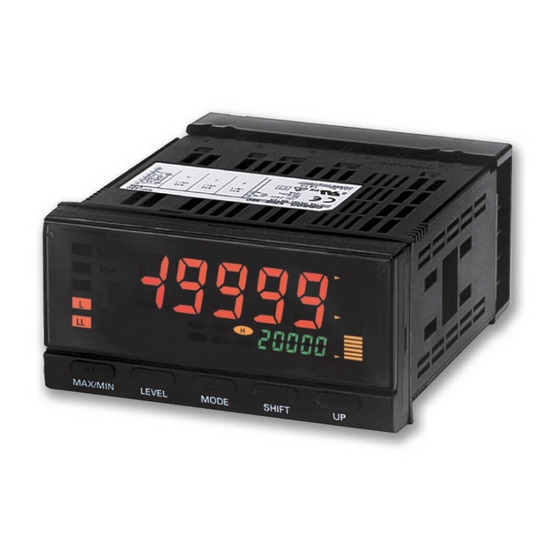
- Page 15 Section 1 Outline 1.2 Component Names and Functions Level/bank display PV display Max/Min status 88888 Position meter Comparative output status 88888 Status indicators SV display SV display status LEVEL Key SHIFT Key MAX/MIN Key UP Key MODE Key Name Function PV display Displays PVs, maximum values, minimum values, parameter names, and error names.
- Page 16 1.3 Internal Block Diagram 1.3 Internal Block Diagram Key Display Drive Transistor Input Analog input converter circuit output circuit terminal EEPROM Contact Drive outputs circuit Wave- Event input Event input shaping circuit terminal circuit Linear output Drive Communications circuit circuit Drive Communications terminal...
- Page 17 Section 2 Preparations 2.1 Mounting ..................2-2 2.2 Using I/O..................2-5...
- Page 18 Section 2 Preparations 2.1 Mounting ■ External Dimensions 101.2 Character size for main display (mm) PV display SV display ■ Panel Cutout Dimensions 120 min. +0.8...
- Page 19 2.1 Mounting ■ Mounting method Insert the K3HB into the mounting cutout in the panel. Insert watertight packing around the Unit to make the mounting watertight. Watertight packing Insert the adapter into the grooves on the left and right sides of the rear case and push until it reaches the panel and is fixed in place.
- Page 20 Section 2 Preparations ■ LCD Field of Vision The H3HB-S is designed to have the best visibility at the angles shown in the following diagram.
- Page 21 2.2 Using I/O 2.2 Using I/O Operating Power Supply Analog Input 100 to 240-VAC models Input B Input A Input A Input B 24-VAC/VDC models Sensor Power Supply/Output Relay/Transistor Outputs Event Input 12-VDC 80-mA HH/H/L/LL Models with terminal blocks models with PASS output models with relay outputs models with relay outputs <K35-1><K35-3>...
- Page 22 30 V rms and 42.4 V peak, and is 60 VDC or less. Recommended Power Supply: S8VS-06024@ (from OMRON) ● Sensor power supply The sensor power can be supplied from terminals B5 and B6. The power supply specifications are outlined below.
- Page 23 2.2 Using I/O <C2> HH, H, L, and LL output model <CPA> PASS output model PASS <Transistor outputs> <T1> NPN output model 8.2 Ω 8.2 Ω 8.2 Ω PASS 8.2 Ω 8.2 Ω <T2> PNP output model 8.2 Ω 8.2 Ω 8.2 Ω...
- Page 24 Section 2 Preparations ● Event inputs Input control signals. The configuration is shown below. TIMING S-TMR 1: TIMING 2: S-TMR 3: HOLD 4: RESET HOLD 5: ZERO 6: COM RESET 7: BANK4 8: BANK2 9: BANK1 10: COM ZERO Models with terminal blocks Models with connectors <1><3>...
- Page 25 2.2 Using I/O ● Analog inputs Input the signal to be measured. The inputs that can be measured by each model are outlined below. Voltage/current inputs Connect the input device to the terminals shown below depending on the input type. Make sure that the maximum rating is not exceeded, even momentarily.
- Page 26 Section 3 Basic Application Methods 3.1 Product height measurement and OK/NG judgement ....3-2 3.2 Panel thickness inspection ............3-5 3.3 Measurement of Disk Eccentricity ..........3-8 3.4 Step inspection ................ 3-10...
-
Page 27: Product Height Measurement And Ok/Ng Judgement
Section 3 Basic Application Methods 3.1 Product height measurement and OK/NG judgement Advantages of Using the K3HB-S • The sampling hold function can be used to use sensors synchronously and display and hold product heights. • The forced-zero function can be used for one-touch zero adjustment. - Page 28 Near Sync sensor K3HB-S 0. 00 2. 00 -3. 00 Display K3HB-S PASS Comparative outputs ■ K3HB-S Setting Details RUN level Parameter Characters Set value Remarks 3. 00 Comparative ✽ set value HH 2. 00 Comparative Example of monitoring in ✽...
- Page 29 Section 3 Basic Application Methods Display adjustment level ( Parameter Characters Set value Remarks disp Display value Present value selection pos-t Position Deviation display meter type pos-h 4. 00 Position meter upper limit Full-scale ±4 mm pos-l -4. 00 Position meter lower limit * Only the parameters required for settings are displayed in the initial...
-
Page 30: Panel Thickness Inspection
3.2 Panel thickness inspection 3.2 Panel thickness inspection Advantages of Using the K3HB-S • Calculation mode K-(A+B) can be used to convert panel thickness to actual size and measure it from the outputs of two displacement sensors. • The forced-zero function can be used for one-touch deviation measurement from a reference panel thickness. - Page 31 Z4W-V25R Sensors K3HB-S display 21. 00 20. 00 19. 00 When K = 70.00 PASS Comparative outputs ■ K3HB-S Settings Details RUN level Parameter Characters Set value Remarks ✽ 20. 50 Comparative Monitoring a difference of set value H ±0.5 mm for a reference...
- Page 32 3.2 Panel thickness inspection Initial setting level ( Parameter Characters Set value Remarks Calculation K-(A+B) in-ta 4-20 Input type A inp. a 1 4. 000 Scaling input value A1 dsp. a 1 21. 00 Scaling display value A1 inp. a2 20.
-
Page 33: Measurement Of Disk Eccentricity
Section 3 Basic Application Methods 3.3 Measurement of Disk Eccentricity Advantages of Using the K3HB-S • The peak-to-peak hold function can be used for simple eccentricity measurement by measuring the difference between the maximum and minimum values for linear sensor signals that change continuously. - Page 34 ON while rotating once or more. K3HB-S display (Reset status) When the workpiece has rotated once or more, the desired value A is measured. ■ K3HB-S Setting Details Initial setting level ( Parameter Characters Set value Remarks Calculation in-ta...
-
Page 35: Step Inspection
Section 3 Basic Application Methods 3.4 Step inspection Advantages of Using the K3HB-S • Calculation mode A-B can be used to measure steps using two displacement sensors. • The forced-zero function can be used to easily adjust the reference step dimension to the actual object. - Page 36 K3HB-S PASS comparative outputs * The previous judgement result is held until the Sync Sensor turns ON. (All outputs turn OFF when RESET input is received.) ■ K3HB-S Setting Details RUN level Parameter Characters Set value Remarks ✽ 2. 50...
- Page 37 Section 3 Basic Application Methods Initial setting level ( Parameter Characters Set value Remarks Calculation in-ta 4-20 Input type A inp. a 1 4. 000 Scaling input value A1 dsp. a 1 21. 00 Scaling display value A1 inp. a2 20.
- Page 38 Section 4 Initialization 4.1 Initialization example ..............4-2...
- Page 39 Section 4 Initialization 4.1 Initialization example Initialization when using the K3HB-S is explained in the following example. <Settings example> 1- to 5-V input is scaled to 0.000 to 1.000 and displayed. • Comparative output H is output when the measurement value reaches 0.700 or higher.
- Page 40 4.1 Initialization example E Set the decimal point position. 1. Set the parameter "dp" to ",,.,,," (initial value) and press the M[MODE] Key. F Set comparison set value H to 0.700 and set comparison set value L to 0.500. 1. Return to the RUN level by pressing the L[LEVEL] key for at least 1 s. (Start operation.) 2.
-
Page 41: Table Of Contents
Section 5 Functions and Operations Knowledge Required for Setting Parameters........5-2 -----Operation Adjustments ----------------------------------------------------- 5.1 Setting Calculations ..............5-9 5.2 Setting Input Types..............5-11 5.3 Setting Scaling Values............. 5-12 5.4 Setting Measurement Operations ..........5-16 5.5 Resetting Measurements............5-20 5.6 Not Performing Measurements for Set Intervals...... 5-21 -----Input Adjustments ------------------------------------------------------------ 5.7 Selecting Operations for Input Errors ........ -
Page 42: Knowledge Required For Setting Parameters
Section 5 Functions and Operations Knowledge Required for Setting Parameters ■ About Levels Levels are groups of parameters. Levels for the K3HB-S are classified as follows: Important Depending on the level, measurements may Measurement continue to be executed or Level... - Page 43 Knowledge Required for Setting Parameters To change a parameter, move to the level where that parameter is found. The current level is shown on the bank/level display when moving between levels. Level/bank Level display Protect level Not lit RUN level * Adjustment level Initial setting level Input adjustment level...
- Page 44 Section 5 Functions and Operations ■ Moving Between Levels Power ON Always displayed, regardless of model and setting. May not be displayed, depending on the model and Less than setting. 3 s min. Adjustment Protect 1 s min. Measurement starts. 3 s min.
- Page 45 Knowledge Required for Setting Parameters Advanced-function A special operation is required to move to the advanced-function setting level. setting level Use the following procedure. Procedure A Move to the initial setting level, press the M[MODE] Key several times to display the "amov" (move to advanced-function setting level) parameter.
- Page 46 Section 5 Functions and Operations ■ Monitoring and Changing Set Values Values set to each parameter are called "set values". Set values can be numerals or characters. When the SV display is lit, it is called the "monitor status". When the SV display is flashing, it is called the "change status".
- Page 47 Knowledge Required for Setting Parameters ■ Confirming and Changing Comparative Set Values Comparative set values are confirmed and changed in RUN level. (The Unit keeps operating even while comparative set values are being confirmed and changed.) The comparative set values from HH to LL are displayed each time the M[MODE] Key is pressed in the operation status immediately after the power is turned ON.
- Page 48 Section 5 Functions and Operations Parameter Setting Procedure A Press the M[MODE] Key several times 123. 4 to display the comparative set value to - 1 9999 be changed. One of the values between HH and LL will flash, according to the displayed comparative set value.
-
Page 49: Setting Calculations
5.1 Setting Calculations 5.1 Setting Calculations Initial setting level The K3HB-S can add, subtract, and display two types of analog inputs, input A and input B. Explanation of Functions Calculation and constant K ■ A • Select to use only input A. - Page 50 Section 5 Functions and Operations ■ B/A × 10000 • Select to display the ratio between input A and input B. ■ (B/A-1) × 10000 • Select to display the error ratio for input B and input A. Set using the following parameter. Parameter Set value Meaning of set value...
-
Page 51: Setting Input Types
5.2 Setting Input Types 5.2 Setting Input Types Initial setting level Set the input types at the next parameter to match the connected input in-ta devices. Set input type A to match the device connected to input A and set input type B to match the device connected to input B. (IN-TA) Parameter Set value... -
Page 52: Setting Scaling Values
Section 5 Functions and Operations 5.3 Setting Scaling Values Initial setting level Set scaling to convert and display input values as any value. Inputs A and B are set separately. One point * <Setting parameter for input A> Parameter Set value Meaning of set value inp. - Page 53 5.3 Setting Scaling Values The decimal point for scaling display values depends on the decimal point position [dp] setting. Parameter Set value Meaning of set value ,,,,, No decimal point ,,,,., One digit below the decimal point is displayed. ,,,.,, Two digits below the decimal Decimal point position point are displayed.
- Page 54 Section 5 Functions and Operations Scaling Parameter Setting Procedure (Scaling Settings for Input A) A Press the L[LEVEL] Key for at least 3 in-ta s in RUN level to move to the initial setting level. 3 s min. 0". Displays " 0"...
- Page 55 5.3 Setting Scaling Values Decimal point position J Press the M[MODE] Key to switch the PV display to the next parameter "dp". ,,. ,,, K Press the S[SHIFT] Key to make the SV display flash. ,,. ,,, • The setting can be changed when the SV starts to flash.
-
Page 56: Setting Measurement Operations
Section 5 Functions and Operations 5.4 Setting Measurement Operations Input adjustment level The K3HB-S has 5 measurement modes, which are set using the tmg-h following parameter. Parameter Set value Meaning of set value (TMG-H) nomal Normal Sampling hold Timing hold... - Page 57 5.4 Setting Measurement Operations Sampling hold • Holds the measurement at the rising edge of the TIMING signal. Important • When the measurement value exceeds the measurement range, a sensor error will occur and all outputs will turn OFF. • Measurements are not performed during RESET input and TIMING inputs are disabled.
- Page 58 Section 5 Functions and Operations Bottom hold • The minimum value is held while measurement is being performed (while the TIMING input is ON) and when the measurement has been completed (when the TIMING input turns OFF) the measurement value is refreshed using the smallest held value. Important * •...
- Page 59 5.4 Setting Measurement Operations Parameter Setting Procedure A Press the L[LEVEL] Key for at least 3 s in RUN level to move to the initial setting level. 3 s min. 0". Displays " 0" is displayed on the level/bank • " display to indicate the initial setting level.
-
Page 60: Resetting Measurements
Section 5 Functions and Operations 5.5 Resetting Measurements When the RESET input turns ON or the [MAX/MIN] Key is pressed for at least 1 s, the maximum value, minimum value, and outputs are cleared. Measurement is not performed during RESET input. Max. -
Page 61: Not Performing Measurements For Set Intervals
Measurement will not start until the time set for s-tmr passes after the power is turned ON. This function can be used for applications such as when the K3HB-S and a rotating body are turned ON at the same time and the rotating body is to be in standby mode until the correct rotation speed has been reached. - Page 62 Section 5 Functions and Operations F Press the S[SHIFT] Key to make the s-tmr SV display flash. 00. 0 • The setting can be changed when the SV display starts to flash. G Use the U[UP] and S[SHIFT] Keys to s-tmr change the set value.
-
Page 63: Selecting Operations For Input Errors
5.7 Selecting Operations for Input Errors 5.7 Selecting Operations for Input Errors Advanced-function setting level The display and operation when the input is exceeding input range can s. err be selected by setting this parameter. (Refer to Input Characteristics in the appendices for input ranges.) (S.ERR) Parameter Set value... - Page 64 Section 5 Functions and Operations C Press the S[SHIFT] Key to make the amov SV display flash. 00000 • The setting can be changed when the SV display starts to flash. D Use the U[UP] and S[SHIFT] Keys to init set the password "-0169".
-
Page 65: Adjusting Timing Inputs
5.8 Adjusting Timing Inputs 5.8 Adjusting Timing Inputs Input adjustment level TIMING inputs can be delayed by adjusting the ON timing delay and on-t OFF timing delay. (ON-T) TIMING signal off-t TIMING input (OFF-T) OFF timing delay ON timing delay Parameter Set value Meaning of set value... - Page 66 Section 5 Functions and Operations ● Timing hold set value set to peak hold Delay processing invalid Power ON due to reset input. Measurement No measurement Peak value 1 No measurement Peak value 2 value RESET TIMING 20 ms 20 ms 20 ms 10 ms 10 ms...
- Page 67 5.8 Adjusting Timing Inputs H Use the U[UP] and S[SHIFT] Keys to off-t change the timing delay. 0010 • Units: ms I Press the M[MODE] Key to switch to step the next parameter. • The set value is registered. J Press the L[LEVEL] Key for at least 1 123.
-
Page 68: Eliminating Drift Near "0
Section 5 Functions and Operations 5.9 Eliminating Drift Near "0" Input adjustment level "Zero limit" is the function that makes measurement values "0" for inputs lower than a set value. Explanation of Functions Zero-limit If the input value is less than the set value, the measurement value becomes "0". This function is effective when display drift and displacement near "0"... - Page 69 5.9 Eliminating Drift Near "0" G Press the S[SHIFT] Key to make the lim-p SV display flash. • The setting can be changed when the SV display starts to flash. H Use the U[UP] and S[SHIFT] Key to lim-p change the zero-limit value. I Press the M[MODE] Key to switch to step the next parameter.
-
Page 70: Averaging Inputs
Section 5 Functions and Operations 5.10 Averaging Inputs Input adjustment level Averaging is a function that makes display and output smooth for input values with dramatic fluctuations, such as spike noise. Explanation of Functions Average processing There are two types of averaging: "simple" and "moving". Select one type. The number of samples ("averaging times") can also be specified for the input values to be averaged. - Page 71 5.10 Averaging Inputs Averaging is set using the following parameters. avg-t Parameter Set value Meaning of set value smpl Simple average Average type (AVG-T) avg-t move Moving average avg-n (AVG-N) Averaging times avg-n 1024 1024 * To not use averaging, set the average type "avg-t" to smpl and the averaging times "avg-n"...
- Page 72 Section 5 Functions and Operations G Press the S[SHIFT] Key to make the avg-n SV display flash. H Use the U[UP] Key to change the avg-n averaging times setting. I Press the M[MODE] Key to switch to tmg-h the next parameter. nomal •...
-
Page 73: Detecting Sudden Input Changes
5.11 Detecting Sudden Input Changes 5.11 Detecting Sudden Input Changes Advanced-function setting level "Previous average comparison" is a function that detects only sudden changes to input signals. Explanation of Functions Previous average comparison Use the previous average comparison to not detect gentle changes and only detect sudden changes. Off-center As shown in the above diagram, when rotating a cylindrical object and measuring the distance from the object using a laser displacement meter, it cannot be judged if the increase in measurement values when... - Page 74 Section 5 Functions and Operations Previous average comparison makes the measurement value the difference between the present input value and the average of all previous input values. Number of Input Display Comparative set value for next input measurements value value = (C )= (V -- -...
- Page 75 5.11 Detecting Sudden Input Changes D Use the U[UP] and S[SHIFT] Keys to set the init password "-0169". Press the M[MODE] Key to move to the advanced-function setting level. f". Displays " f" is displayed on the level/bank display to •...
-
Page 76: Changing Comparative Output Patterns
Section 5 Functions and Operations 5.12 Changing Comparative Output Patterns Initial setting level Compares the measurement value and comparative set value and out-p outputs the comparative result. The output pattern is set using the following parameter. (OUT-P) Parameter Set value Meaning of set value nomal Standard output... - Page 77 5.12 Changing Comparative Output Patterns Parameter Setting Procedure A Press the L[LEVEL] Key for at least 3 s in RUN level to move to the initial setting level. 0". Displays " 3 s min. 0" is displayed on the level/bank •...
-
Page 78: Preventing Output Chattering
Section 5 Functions and Operations 5.13 Preventing Output Chattering Advanced-function setting level Comparative output chattering results from drift in measurement value near the comparative set value. Chattering can be prevented by adjusting the hysteresis value. Explanation of Functions Hysteresis Hysteresis is a range between the value for which a comparative output turns ON and the value for which the comparative output turns OFF. - Page 79 5.13 Preventing Output Chattering Parameter Setting Procedure A Press the L[LEVEL] Key for at least 3 s in RUN level to move to the initial setting level. 0". 3 s min. Displays " 0" is displayed on the level/bank • " display to indicate the initial setting level.
- Page 80 Section 5 Functions and Operations J Press the L[LEVEL] Key for at least 1 123. 4 s to return to RUN level. 123. 4 1 s min. 5-40...
-
Page 81: Outputting At Set Intervals
5.14 Outputting at Set Intervals 5.14 Outputting at Set Intervals Advanced-function setting level Shot output is the function that turns OFF a comparative output after a shot set interval after it turns ON. The following diagram shows the operation when timing hold is set to normal and shot output is set to 10 ms. - Page 82 Section 5 Functions and Operations Parameter Setting Procedure A Press the L[LEVEL] Key for at least 3 s in RUN level to move to the initial setting level. 3 s min. 0". Displays " 0" is displayed on the level/bank •...
- Page 83 5.14 Outputting at Set Intervals J Press the L[LEVEL] Key for at least 1 123. 4 s to return to RUN level. 123. 4 1 s min. Delaying output OFF timing → P.5-44 Remarks 5-43...
-
Page 84: Delaying Output Off Timing
Section 5 Functions and Operations 5.15 Delaying Output OFF Timing Advanced-function setting level Output OFF delay is the function that delays the OFF timing for comparative results. Shot output (shot) is given priority over OFF delay (off-d). OFF delay will be disabled if shot output is set to anything other than "0", regardless of the OFF delay setting. - Page 85 5.15 Delaying Output OFF Timing E Press the M[MODE] Key several times off-d to change the PV display to "off-d". F Press the S[SHIFT] Key to make the off-d SV display flash. 0000 • The setting can be changed when the SV display starts to flash.
-
Page 86: Holding Measurement Status
Section 5 Functions and Operations 5.16 Holding measurement status Measurement values, maximum values, minimum values, and output status can be held while the HOLD input is ON. Comparative set vaLue HH/H Comparative set value LL/L HOLD input Output HH/H Output LL/L •... -
Page 87: Holding Already Output Comparative Outputs
5.17 Holding Already Output Comparative Outputs 5.17 Holding Already Output Comparative Outputs Advanced-function setting level Output refresh stop is the function that holds output comparative o-stp outputs. While comparative outputs are being held, the comparative output status and display color are also held but measurement continues. - Page 88 Section 5 Functions and Operations D Use the U[UP] and S[SHIFT] Keys to init set the password "-0169". Press the M[MODE] Key to move to the f". Displays " advanced-function setting level. f" is displayed on the level/bank • " display to indicate the advanced- function setting level.
-
Page 89: Allocating Other Outputs To Pass Output
5.18 Allocating Other Outputs to PASS Output 5.18 Allocating Other Outputs to PASS Output Advanced-function setting level In the default settings, PASS signals are output from the PASS output pass terminal. The "PASS output change" parameter can be set to output comparative output status details other than PASS or errors from the PASS output terminal. - Page 90 Section 5 Functions and Operations E Press the M[MODE] Key to change the pass PV display to "pass". pass F Press the S[SHIFT] Key to make the pass SV display flash. pass • The setting can be changed when the SV display starts to flash.
-
Page 91: Reversing Output Logic
5.19 Reversing Output Logic 5.19 Reversing Output Logic Advanced-function setting level The comparative output logic for comparative results is set using the out-n following parameter. However, only the actual output is reversed. The operation logic for the comparative output status is not reversed. (OUT-N) Operation Parameter... - Page 92 Section 5 Functions and Operations F Press the S[SHIFT] Key to make the out-n SV display flash. • The setting can be changed when the SV display starts to flash. G Use the U[UP] Key to change the set out-n value.
-
Page 93: Setting The Present Measurement Value To A Reference
• The forced-zero and forced-zero clear operations are stored in the internal non-volatile memory of the K3HB-S, so the status is held even if the power supply is turned ON again. There are two methods for executing and clearing forced-zero: using key operations and using ZERO inputs. -
Page 94: Setting The Present Measurement Value To "0" Again Using The Forced-Zero Reference
Section 5 Functions and Operations 5.21 Setting the present measurement value to "0" again using the forced-zero reference Advanced-function setting level The tare zero function shifts the present measurement value to "0" again using the forced-zero reference. Explanation of Functions Tare zero This function is enabled when each of two different types of compound are to be weighed, as shown in the following example. - Page 95 5.21 Setting the present measurement value to "0" again using the forced-zero reference Tare zero is set using the following parameter. t-zr Parameter Set value Meaning of set value Tare zero enabled Tare zero (T-ZR) t-zr Tare zero disabled Parameter Setting Procedure A Press the L[LEVEL] Key for at least 3 s in RUN level to move to the initial setting level.
- Page 96 Section 5 Functions and Operations H Press the M[MODE] Key to switch to z-trm the next parameter. • The set value is registered. I Press the L[LEVEL] Key for at least 1 s to return to the initial setting level. 1 s min.
-
Page 97: Compensating Forced-Zero References
5.22 Compensating Forced-zero References 5.22 Compensating Forced-zero References Advanced-function setting level Zero-trimming is the function that compensates the forced-zero shift value based on the measurement value for an OK object (PASS data) while forced-zero is being executed. This function can be used if the timing hold setting is sampling hold, peak hold, or bottom hold. Explanation of Functions Zero-trimming Zero-trimming can be used if the timing hold parameter is set to sampling hold, peak hold, or bottom hold. - Page 98 Section 5 Functions and Operations Parameter Setting Procedure A Press the L[LEVEL] Key for at least 3 s in RUN level to move to the initial setting level. 3 s min. 0". Displays " 0" is displayed on the level/bank •...
- Page 99 5.22 Compensating Forced-zero References J Press the L[LEVEL] Key for at least 1 123. 4 s to return to RUN level. 123. 4 1 s min. Remarks Setting the present measurement value to a reference value of "0" (forced-zero) → P.5-53 5-59...
-
Page 100: Changing Display Refresh Periods
Section 5 Functions and Operations 5.23 Changing Display Refresh Periods Display adjustment level When measurement values change rapidly and the display changes with d. ref the measurement values, flickering often occurs and the display becomes difficult to read. The flickering can be suppressed and the display made easier to read in such situations by delaying the display refresh period. -
Page 101: Holding Maximum And Minimum Values
5.24 Holding maximum and minimum values 5.24 Holding maximum and minimum values The maximum and minimum values during measurement can be held. • The maximum and minimum values are reset when the power is turned OFF, RESET inputs are received, the [MAX/MIN] Key is pressed for 1 s, S-TMR inputs are received, and when returning to RUN level from levels other than adjustment and protect levels. -
Page 102: Changing Normal Display Values To Maximum And Minimum Values
Section 5 Functions and Operations 5.25 Changing Normal Display Values to Maximum and Minimum Values Display adjustment level The PV display value after the power has been turned ON, disp immediately after moving to RUN level, or immediately after automatic display return in RUN or adjustment levels can be set to either "present value", "maximum value", or "minimum value". -
Page 103: Setting The Step For Changing The Rightmost Digit
5.26 Setting the Step for Changing the Rightmost Digit 5.26 Setting the Step for Changing the Rightmost Digit Input adjustment level The step for changing the rightmost digit on the display is set using the step following parameter. Parameter Set value Meaning of set value (STEP) Step value... -
Page 104: Displaying/Not Displaying Comparative Set Values
Section 5 Functions and Operations 5.27 Displaying/Not Displaying Comparative Set Values Display adjustment level Comparative set values can be displayed or not displayed on the SV sv. dsp display during operation. This is set using the following parameter. (SV.DSP) Parameter Set value Meaning of set value Comparative set value not... -
Page 105: Changing Display Colors
5.28 Changing Display Colors 5.28 Changing Display Colors Display adjustment level The PV display color can be switched when the comparative result color changes from PASS to HH, H, L, or LL, or when an input error occurs during operation in RUN, adjustment, or protect levels. (COLOR) This function is called "display color selection"... - Page 106 Section 5 Functions and Operations F Press the M[MODE] Key to switch to disp the next parameter. • The set value is registered. G Press the L[LEVEL] Key for at least 1 123. 4 s to return to RUN level. 123.
-
Page 107: Using Position Meters
5.29 Using Position Meters 5.29 Using Position Meters Display adjustment level The meters on the right side of the front panel with 20 sections is pos-t called the "position meter" and shows the position of the displayed value (present value, maximum, or minimum) in relation to any values set using position meter upper and lower limits. - Page 108 Section 5 Functions and Operations Parameter Setting Procedure A Press the L[LEVEL] Key for at least 3 s in RUN level to move to the initial setting level. 0". 3 s min. Displays " 0" is displayed on the level/bank •...
- Page 109 5.29 Using Position Meters K Use the U[UP] and S[SHIFT] Keys to pos-l change the position meter lower limit - 1 0000 setting. L Press the M[MODE] Key to switch to sv. dsp the next parameter. • The parameter for the position meter lower limit is registered.
-
Page 110: Forcing Automatic Return To Normal Display
Section 5 Functions and Operations 5.30 Forcing Automatic Return to Normal Display Display adjustment level If no key operations are made after switching the display in RUN or adjustment levels, the display will automatically return to the display after the power is turned ON. The time until automatic display return can be set and the automatic display return can be disabled. -
Page 111: Performing Output Tests
5.31 Performing Output Tests 5.31 Performing Output Tests Output test level The output test function is used to set a test measurement value using test the keys and to check the comparative output against the set comparative set value. (TEST) The test measurement value is set using the following parameter. -
Page 112: Using Comparative Set Value Banks
5.32 Using Comparative Set Value Banks Advanced-function setting level/Comparative set value level The K3HB-S has 8 areas (banks) where groups of comparative set values are set beforehand. Comparative set values can be changed easily by switching these banks. This function is called "bank selection". - Page 113 5.32 Using Comparative Set Value Banks Parameter Setting Procedure A Press the L[LEVEL] Key for at least 3 s in RUN level to move to the initial setting level. 3 s min. 0". Displays " 0" is displayed on the level/bank •...
- Page 114 Section 5 Functions and Operations One point * I Press the L[LEVEL] Key for at least 1 123. 4 s to return to RUN level. 123. 4 1 s min. "B" is lit to indicate that the bank is enabled. * If the bank selection is not set to OFF, the comparative set values set in RUN level HH, H, L, and LL are registered to the HH, H, L, and LL of bank 0.
- Page 115 5.32 Using Comparative Set Value Banks ■ 2. Setting the comparative set values for each bank Once the bank selection method has been specified, set the sv. bnk comparative set values for each bank. Comparative set values are set using the following parameter. (SV.BNK) Parameter Set value...
- Page 116 Section 5 Functions and Operations H Use the U[UP] and S[SHIFT] Keys to sv1. h change the set value. 10000 I Press the M[MODE] Key to switch to sv1. l the next parameter. - 1 9999 • The parameter changed in step H is registered.
-
Page 117: Copying Bank Comparative Set Values
5.33 Copying bank comparative set values 5.33 Copying bank comparative set values The bank copy function is used to specify a bank between 0 and 7 and copy copy the group of comparative set values in that bank to all banks. Parameter Setting Procedure (COPY) A Press the L[LEVEL] Key for at least 3... -
Page 118: Initializing All Settings
Section 5 Functions and Operations 5.34 Initializing all settings Important * Initialization can be used to start settings over again from the default settings. Refer to Parameter List in the Appendices for information on init default set values. Parameter Setting Procedure (INIT) A Press the L[LEVEL] Key for at least 3 s in RUN level to move to the initial... - Page 119 5.34 Initializing all settings H Press the L[LEVEL] Key for at least 1 s to return to the initial setting level. 1 s min. I Press the L[LEVEL] Key for at least 1 123. 4 s to return to RUN level. 123.
-
Page 120: Limiting Key Operations
Section 5 Functions and Operations 5.35 Limiting Key Operations Protect level The "key protect" function limits level and parameter changes using run. pt key operations. There are 4 kinds of key protection. The parameters, settings, and details of each kind of protection are outlined below. : Enabled, : Prohibited (RUN.PT) - Page 121 5.35 Limiting Key Operations ● Forced-zero protect (Limits key-operated execution and clearing of forced-zero and tare zero.) Parameter Set value Restriction details Forced-zero using key operations and tare zero execution/clear: Enabled Zero protect zr.pt Forced-zero using key operations and tare zero execution/clear: Prohibited Parameter Setting Procedure A Press the L[LEVEL] and M[MODE]...
- Page 122 Section 6 User calibration 6.1 About user calibration ..............6-2 6.2 User calibration operation............6-4...
- Page 123 The K3HB-S is calibrated correctly at shipment, so there is normally no need for the user to calibrate it. The K3HB-S has a function to calibrate analog inputs that can be used for user calibration. OMRON, however, does not accept any responsibility for the results of user calibration using this function.
- Page 124 6.1 About user calibration Calibration flowchart User calibration is performed according to the following flowchart. User calibration is performed for input A if "A" is included in the calculation and input B if "B" is included in the calculation. Calibration is performed on both inputs A and B if both "A" and "B" are included in the calculation.
- Page 125 Connect the Calibrator (standard voltage generator or standard current generator) to the input terminal for the input type to be calibrated. Use a Calibrator with enough precision for the accuracy of the K3HB- ■ Key operation procedure Perform the operation according to the following procedure.
- Page 126 6.2 User calibration operation Operation in Parameter Operation Procedure calibration level A Use the procedure outlined above to move to the calibration level. • The aging timer is displayed. u". Displays " • The aging timer is a 30-minute countdown timer that counts until 0 is reached.
- Page 127 Section 6 User calibration G Repeat steps D to F to temporarily register the calibration lower limit. • When temporary registration has been completed, the parameter for registration "str" is displayed. H Press the S[SHIFT] Key to make the SV display flash. •...
- Page 128 Section 7 Troubleshooting 7.1 Error displays................7-2 7.2 Countermeasures ..............7-3...
- Page 129 Contact the point of purchase or your OMRON representative. a.err Normal In the K3HB-S factory settings, the In the initial setting level, set the input operation input type is set to 4 to 20 . When type and other settings to suit the b.err...
- Page 130 ON. timer" parameter set value too to an appropriate value. long? The K3HB-S can have startup compensation for up to 99.9 s. Is the HOLD input still ON? Turn OFF the HOLD input. If the HOLD input remains ON and the power is turned ON, the display remains on "-----"...
- Page 131 Appendices Specifications..................A-2 Available Models................A-5 Model Numbers ................A-6 Parameter list..................A-7 Parameter display conditions............A-11 About parameters ................A-12 Sampling and comparative output response times ......A-14 No Measurement Status ..............A-18...
-
Page 132: Specifications
Appendices Specifications ■ Ratings Power supply voltage 100 to 240 VAC (50/60 Hz) 24 VAC (50/60 Hz)/VDC Allowable power supply voltage 85% to 110% of the rated power supply voltage range Power consumption 100 to 240 VAC: 18 VA max., 24 VAC/VDC: 11 VA/7W max. Input range (measurement... - Page 133 Specifications ■ Characteristics Sampling period One input: 0.5 ms; Two inputs: 1 ms Accuracy One input: ±0.1% FS ±1 digit max. (at 23 ± 5 °C) Two inputs: ±0.2% FS ±1 digit max. (at 23 ± 5 °C) Display range -19999 to 99999 For one input: OFF →...
- Page 134 Appendices ■ Input characteristics Input type Setting Specified range Accuracy range 0-20 0 to 20 mA -2 to 22 mA 4-20 4 to 20 mA 2 to 22 mA 0 to 5 V -0.5 to 5.5 V For 1 input: ±0.1% FS ± 1 digit max. (for 23±5°C) For 2 inputs: ±0.2% FS ±...
-
Page 135: Available Models
■ Base Units Model Supply Part Applicable sensor Applicable relay/ Applicable event voltage number power supply/ transistor outputs input boards output boards boards 100 to K3HB-SSD K33-CPA K34-C1 K35-1 240 VAC 100-240VAC K33-A K34-C2 K35-2 K34-T1 K35-3 24 VAC/ K3HB-SSD K34-T2 K35-4 24VAC/VDC ■... -
Page 136: Model Numbers
Appendices Model Numbers K3HB-SSD-@@@ @ Basic model Code Series K3HB Linear Sensor Indicator K3HB Series Input specifications Code Input specifications Linear sensor input Auxiliary output and external power supply specifications Code Auxiliary output and external power supply specifications Relay, SPDT, 1 point, PASS, 12 VDC 80... - Page 137 Parameter list Parameter list Enter the set value before using. Level Parameter name Display Setting range Initial Unit value value run.pt 0 to 2 RUN/adjustment protect set.pt 0 to 2 Setting level protect Protect wt.pt off, on Setting change protect zr.pt off, on Forced-zero protect - - 1 9999 to 99999...
- Page 138 Appendices Level Parameter name Display Setting range Initial Unit value value tmg-h nomal, s-h, p-h, nomal Timing hold b-h, p-p on-t 0 to 4999 ON timing delay off-t 0 to 4999 OFF timing delay Input z-lim off, on Zero-limit adjustment lim-p 0 to 99 Zero limit value step off, 2, 5, 10...
-
Page 139: Parameter List
Parameter list Level Parameter name Display Setting range Initial Unit value value s?.bnk 0 to 7 Comparative set value bank s?0.hh - 1 9999 to 99999 99999 Comparative set value 0HH s?0.h - 1 9999 to 99999 99999 Comparative set value 0H s?0.l - 1 9999 to 99999 - 1 9999 Comparative set value 0L... - Page 140 Appendices Level Parameter name Display Setting range Initial Unit value value init off, on Set value initialization pass ll, l, pass, h, hh, pass PASS output change hys 0 to 9999 Hysteresis off-d 0 to 1999 Output OFF delay shot 0 to 1999 Shot output out-n n-o, n-c n-o *1...
-
Page 141: Parameter Display Conditions
Parameter display conditions Parameter display conditions Unit Level Parameter name Display Input Output Setting Conditions <1 to 4> <C1> <C2> <T1 to 2> <CPA> RUN/adjustment protect run.pt Setting level protect set.pt Protect Setting change protect wt.pt Forced-zero protect zr.pt Measurement value PASS output change = PASS or ERR Measurement value/comparative set value HH When the Output Unit is only <CPA>, change in PASS output = HH. -
Page 142: About Parameters
Appendices About parameters RUN Level Measurement value Comparative set value HH Power ON LEVEL 99999 -19,999 to 99,999 3 s min. Measurement stopped Protect level To the initial Measurement value L + M Comparative set value H RUN PT: setting level run.pt 99999 LEVEL MODE... - Page 143 About parameters Initial setting level Input adjustment level TMG-H: CAL: Calculation LEVEL INP.B1: inp.b1 tmg-h Less than 1 s Timing hold A, B, K-A, A+B, A-B, K-(A+B), Scaling input value B1 Normal, sampling, 4.000 nomal B/A×10000, (B/A-1)×10000 -19,999 to 99,999 peak, bottom, peak-to-peak IN-TA: Input type A DSP.B1:...
-
Page 144: Sampling And Comparative Output Response Times
Appendices Sampling and comparative output response times The K3HB-S sampling and comparative output response times differ depending on the calculations, timing hold type, and, for simple averaging, the averaging times. Refer to the following description for details. ■ Output refresh period The K3HB-S repeats input reads, calculation, and judgement output processing. - Page 145 Sampling and comparative output response times ■ Output response time The comparative output response time is the sum of the data processing time and the output (relay or transistor) response time. ● One input 0.5 ms 0.5 ms 0.5 ms Data processing time Output response...
- Page 146 Appendices Example 3 The Unit operates as shown in the diagram to the right for the settings shown in the Input Input Input Input Input Input Input Input Input Input Input Input table below. Input A Input B Calculation Output Output Timing hold mode Normal...
- Page 147 Sampling and comparative output response times ■ Relationship between timing signals and reset or hold signals The following tables show whether or not measurement is performed for each signals timing input, when timing hold is not set to normal. ● Timing signal and reset signal TIMING RESET Measured →...
-
Page 148: No Measurement Status
Appendices No Measurement Status When no measurement value has been determined, a "no measurement" status exists. The PV display for no measurement is "- ----" and all outputs are OFF. ----- 88888 A no measurement status occurs in the following circumstances. •... - Page 149 Index Adjustment ........5-2, 5-3, 5-4 Initial setting level ....3-3, 3-7, 3-9, 3-12 Advanced-function settings....5-2, 5-3, 5-5 Initialization........5-2, 5-3, 5-4 Analog input ............2-9 Input adjustment .......5-2, 5-3, 5-4 Automatic display return .......5-70 Input adjustment level..... 3-3, 3-7, 3-9, 3-12 Average processing ......
- Page 150 Sampling hold .... 3-3, 3-12, 5-16, 5-17, 5-25 Scaling .... 1-3, 3-3, 3-7, 3-9, 3-12, 4-2, 5-12 Sensor power supply ........2-6 Set values ............5-6 Setting change protect ........5-80 Setting initialization ........5-78 Setting level protect ........5-80 SHIFT key ............1-4 Shot output........1-3, 5-41, 5-44 Simple average ..........5-30 Standard output ..........5-36 Startup compensation timer ....
Need help?
Do you have a question about the K3HB and is the answer not in the manual?
Questions and answers