Table of Contents
Troubleshooting

Subscribe to Our Youtube Channel
Related Manuals for Omron K7GE-MG


Summary of Contents for Omron K7GE-MG
- Page 1 Overview Procedure Insulation Resistance Installation and Monitoring Device Wiring Functions Related User's Manual to Measurement K7GE-MG Using Setting Parameters Remote Monitoring Troubleshooting Appendices Index N224-E1-01...
- Page 2 No patent liability is assumed with respect to the use of the information contained herein. Moreover, because OMRON is constantly striving to improve its high-quality products, the information contained in this manual is subject to change without notice. Every precaution has been taken in the preparation of this manual. Neverthe- less, OMRON assumes no responsibility for errors or omissions.
-
Page 3: Preface
In this manual, "K7GE-MG" refers to the K7GE-MG with its Main Unit connected to the Probe Units. It is assumed that the load that the K7GE-MG measures is a motor. Before you use it for other equipment such as a heater or transformer, carefully study the operating specifications of the K7GE-MG. -
Page 4: Terms And Conditions Agreement
Omron’s exclusive warranty is that the Products will be free from defects in materials and workmanship for a period of twelve months from the date of sale by Omron (or such other period expressed in writing by Omron). Omron disclaims all other warranties, express or implied. -
Page 5: Application Considerations
Disclaimers Performance Data Data presented in Omron Company websites, catalogs and other materials is provided as a guide for the user in determining suitability and does not constitute a warranty. It may represent the result of Omron’s test conditions, and the user must correlate it to actual application requirements. Actual performance is subject to the Omron’s Warranty and Limitations of Liability. -
Page 6: Definition Of Precautionary Information
Definition of Precautionary Information The following notation is used in this manual to provide precautions required to ensure safe usage of the K7GE-MG Insulation Resistance Monitoring Device. The safety precautions that are provided are extremely important to safety. Always read and heed the information provided in all safety precautions. - Page 7 Safety Precautions CAUTION Minor injury due to electric shock may occasionally occur. Do not touch the Product except for any buttons (keys) while power is being supplied. Always connect the protective earthing terminal ( ) to a ground. Use AWG 16 for the protective conductor. If the wiring material is inserted in a shallow position, it may cause property damage due to ignition.
-
Page 8: Precautions For Safe Use
When inserting a flat-blade screwdriver into the release holes, operate with a force of 15•N or less. (11) K7GE-MG may be subject to radio disturbances. Do not install the Product near equipment that generates high frequencies or surges. - Page 9 (23) Check terminal polarity when wiring and wire all connections correctly. Do not wire the input and output terminals incorrectly. (24) K7GE-MG provides 50 VDC of Megger voltage. Do not use on equipment that may be damaged by this voltage.
-
Page 10: Precaution For Correct Use
(18) Set the "Motor stop waiting time" setting value to at least the time from when the contactor is turned off until the load completely stops. (19) If you accidentally drop K7GE-MG, the inside of the Product may be damaged, so do not use it. (20) Do not wire anything to the release holes. -
Page 11: Regulations And Standards
Regulations and Standards Regulations and Standards Conformance to Safety Standards • For wiring from the Probe Unit to the load, use a Class CC, Class J, or Class T fuse with a rated current of 7A or less. • The protection provided by the device may be impaired if the device is used in a manner that is not specified by the manufacturer. - Page 12 Regulations and Standards Measurement Category The measurement category classifies the places and equipment which you can connect to the measurement terminals, as prescribed in EN/IEC 61010-2-030. Each category is as follows. CAT I: Equipment to connect to circuits where Service measures are taken to limit transient entry wire...
-
Page 13: Terminology
K7GE-MG "K7GE-MG" refers to the K7GE-MG with its Main Unit connected to the Probe Units. Megohmmeter An instrument that measures the insulation resistance of electrical products and indoor wiring, also called an insulation resistance meter. -
Page 14: Manual Structure
Manual Structure Manual Structure Page Structure Level 1 heading Level 2 heading Level 2 heading Gives the current headings. Special information Icons indicate precautions, additional information, or reference information. Page tab Gives the number of the main section. A step in a procedure Indicates a procedure. -
Page 15: Revision History
Revision History Revision History A manual revision code appears as a suffix to the catalog number on the front cover of the manual. N224-E1-01 Revision code Revision code Date Revised content January 2021 Original production Insulation Resistance Monitoring Device User’s Manual (N224) - Page 16 Revision History Insulation Resistance Monitoring Device User’s Manual (N224)
-
Page 17: Sections In This Manual
Sections in this Manual Overview Procedure Installation and Wiring Functions Related to Measurement Using Setting Parameters Remote Monitoring Troubleshooting Appendices Index Insulation Resistance Monitoring Device User’s Manual (N224) -
Page 18: Table Of Contents
CONTENTS Preface ........................1 Terms and Conditions Agreement ................2 Warranty, Limitations of Liability ........................2 Application Considerations .......................... 3 Disclaimers ..............................3 Precautions....................... 4 Definition of Precautionary Information......................4 Symbols ............................... 4 Precautions for Safe Use ..................6 Precaution for Correct Use..................8 Regulations and Standards .................. - Page 19 Section 3 Installation and Wiring Dimensions ..........................3-2 Installation..........................3-3 Setting the Channel Number ....................3-6 How to Connect to the Push-In Plus Terminal Blocks ............3-7 I/O Wiring..........................3-10 Wiring the Communications Cable ..................3-13 Setting the Unit Number ..................... 3-14 Connecting to a Load or Contactor ...................
- Page 20 Input Specifications of Trigger Input Terminals ..................A-3 Output Specifications of Transistor Output Terminals ................A-4 Input Specifications of Voltage Input Terminals..................A-4 Communications Specifications........................A-5 A-2 Setting Parameters List ......................A-6 A-3 Setting Parameter Flow......................A-7 A-4 K7GE-MG Logging Tool ......................A-8 Index Insulation Resistance Monitoring Device User’s Manual (N224)
-
Page 21: Overview
This section describes the features, model number legend, nomenclature and functions, system configuration, and safety precautions of the K7GE-MG. 1-1 Overview ........... . . 1-2 1-2 Features . -
Page 22: Overview
Probe Unit Probe Unit Main Unit K7GE-MG supports a motor as a measurement load. If you want to measure other loads such as a heater or transformer, carefully study the operating specifications of the K7GE-MG before use. 1 - 2... -
Page 23: Features
More Support for the Safety Functions • The K7GE-MG is always monitoring the OFF state of the loads and the power line. K7GE-MG does not start measurement even if it receives a measurement start signal during load operation. In addition, K7GE-MG will stop the measurement immediately if the load restarts during the measurement. - Page 24 • If you connect the auxiliary contact of the contactor to the trigger input terminal of the K7GE-MG, you can use it as a measurement start signal. It contributes to the reduction of parts because no additional sequence is required.
- Page 25 1 Overview Enables Remote Trend Monitoring • K7GE-MG automatically collects the measured Measurement values of loads with the communications value Load 1 function. You can monitor the equipment from a Load 2 remote location. Remote monitoring greatly Alarm value 1...
-
Page 26: Model Number Legend
1 Overview Model Number Legend This section shows the model number legend of the K7GE-MG Main Unit and Probe Units. • Main Unit □ K7GE-MG M (2) (3) Meaning Base model Unit type Power supply voltage K7GE-MG Insulation Resistance Monitoring Device... -
Page 27: Insulation Resistance Measurement And Monitoring System
Insulation Resistance Measurement and Monitoring System K7GE-MG is automated according to the procedure of manual measurement and monitoring by Megohmmeter. The flowchart of measurement and monitoring of K7GE-MG is shown below together with manual measurement by Megohmmeter. Auxiliary K7GE-MG MC-a... -
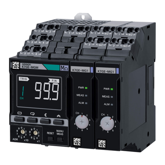
Page 28: Nomenclature And Functions
1 Overview Nomenclature and Functions Appearance Main Unit Probe Unit Symbol Name Operation DIN Track mounting hook Used for mounting to the DIN Track. Right connector Connects the Probe Unit. Right connector cover A cover for preventing the entry of dust and dirt into the connectors. Remove this cover when combining the Main Unit and Probe Units, and during expansion of Probe Units. - Page 29 1 Overview Front Section: Main Unit Symbol Name Operation Alarm output Displays the alarm judgment results of automatic measurement in three colors. indicator Green: Normal Yellow: Warning (Alarm 1 occurrence) Red: Critical (Alarm 2 occurrence) If the status is different across multiple channels, the display color is decided in the priority order of red (critical) >...
- Page 30 1 Overview Symbol Name Operation Unit Number Sets to set the unit number during communications. Setting Switch Status display MANU Indicates the manual measurement state. Indicates that a system error occurred. Indicates that it is time to replace the Main Unit (guideline). LVL/CH display Displays the level*, or the value of the channel number.
- Page 31 1 Overview Front Section: Probe Unit Symbol Name Operation PWR indicator (green) Indicates that the Probe Unit power is ON. MEAS indicator (green) Indicates that measurement is in progress for the load connected to the Probe Unit. ALM indicator (red) Indicates that an alarm occurred in the load connected to the Probe Unit.
- Page 32 1 Overview Terminal Section: Main Unit Terminal Symbol Name Operation Number 1 and 2 Operation Connect the operation power supply to the Main Unit. power supply 3 and 4 Trigger input Input terminals of the external contact from where a trigger signal is applied.
- Page 33 1 Overview Terminal Section: Probe Unit Terminal Symbol Name Operation Number 1 and 3 Voltage input Connect the load terminals. No. 1: Connect the R-phase in a 3-phase system, and the L-phase in a single-phase system No. 3: Connect the S-phase in a 3-phase system, and the N-phase in a single-phase system Use the terminal No.
-
Page 34: Internal Block Diagram
1 Overview Internal Block Diagram This is an internal block diagram of the state when the Main Unit and the Probe Units are connected. The following describes the main configuration elements. MC-a Main Unit Probe Unit 1 Trigger input Display Voltage switch Discharge... - Page 35 The same thing happens when the insulation resistance value is extremely low even if the load is properly turned OFF. To protect the load and the peripheral equipment, as well as the internal circuit of the K7GE-MG from such an overcurrent, the K7GE-MG is equipped with a current limiter circuit which limits the overcurrent.
-
Page 36: System Configurations
1 Overview System Configurations Minimum Configuration This is the minimum configuration for monitoring the insulation resistance using the K7GE-MG. The auxiliary contact of the contactor inserted in Measurement MC-a starts at auxiliary front of the load can be used as the measurement... - Page 37 Main Unit is turned OFF. To know the timing of measurement end, you can use status output during measurement in the K7GE-MG. Status output during measurement turns ON when the measurement operation starts and turns OFF when measurement ends. This change from ON to OFF is the timing when measurement ends.
-
Page 38: Safety Precautions
Be sure to install the contactor in front of the load to be measured. The K7GE-MG uses the same Megger method as a Megohmmeter for detecting insulation resistance. The Megger method measures resistance values with a measuring circuit connected between the charged section and the non-charged section. -
Page 39: Procedure
Procedure This section describes the procedure from preparation to startup of the K7GE-MG. 2-1 Procedure ........... . 2-2 (1) Advance Preparation . -
Page 40: Advance Preparation
2 Procedure Procedure The procedure for starting actual operation is MC-a shown using a system that measures three loads as an example. Interlock The procedure is described in the following five steps. Steps Measurement start signal (1) Advance Preparation (2) Installation and Wiring Measurement starts at auxiliary contact OFF (3) Initial Setting... -
Page 41: Installation And Wiring
2 Procedure (2) Installation and Wiring Connect three Probe Units to one Main Unit. • Remove the right connector cover of the Main Unit and the left connector cover of the Probe Units. Use the Probe Unit on the right end with the right connector cover attached. - Page 42 Supply the operation power from a system different from that of the load. If the same system is used, the power supply to the K7GE-MG will turn OFF when the load contactor turns OFF, and you may not be able to perform measurement.
-
Page 43: Initial Setting
Unit to 2 and that of the third Probe Unit to 3. Always set the channel number to a serial number starting from 1. The K7GE-MG will not operate properly if the channel numbers are not set sequentially from 1 such as 2, 3 and 4 or 1, 2 and 4. - Page 44 2 Procedure • Press the Shift key again to change the setting value. TRIG The digits that can be changed start flashing. MANU ERR • Press the Up Key several times to set the setting value to 3. TRIG In this example, the total number of channels is set to 3 because three Probe Units are used.
-
Page 45: Test Operation With Manual Measurement
2 Procedure (4) Test Operation with Manual Measurement Make sure the load contactor is turned OFF. • Immediately after returning to Operation Level, the TRIG measurement standby is established without starting ---- measurement even if the auxiliary contact of the contactor is MANU ERR turned OFF. -
Page 46: Starting Operation
2 Procedure Manual measurement is ended. • Press the Manual Measurement Key for 1 second to end MANU TRIG manual measurement, and the K7GE-MG will return to MEAS ---- 1 second measurement standby in the Operation Level. MANU In addition, the measurement will be ended automatically 3 minutes after the start of manual measurement. - Page 47 Start actual operation. • Start actual operation if there is no problem in the series of operations of the K7GE-MG and the operation of peripheral equipment including loads and the measurement values. 2 - 9 Insulation Resistance Monitoring Device User’s Manual (N224)
-
Page 48: Troubleshooting
2 Procedure Troubleshooting If the K7GE-MG does not operate properly after performing the procedure, see the correction in the No. **" in the procedure. table below corresponding to the reference number " Problems Cause Correction ERR indicator is lit, A system error occurred. - Page 49 MANU channel, but fail during measurement, or the OFF, and all loads stop is flashing. K7GE-MG detected that the completely within the time insulation resistance is period of the Motor Stop extremely low. Waiting Time setting parameter.
- Page 50 2 Procedure 2 - 12 Insulation Resistance Monitoring Device User’s Manual (N224)
- Page 51 Installation and Wiring This section describes the installation and wiring of the K7GE-MG device. Before you proceed with installation and wiring, be sure to thoroughly read Precautions for Safe Use on page 6. 3-1 Dimensions ........... 3-2 3-2 Installation .
-
Page 52: Installation And Wiring
3 Installation and Wiring Dimensions Main Unit (1.9) (Unit: mm) Probe Unit 17.5 (7.6) (0.9) (Unit: mm) 3 - 2 Insulation Resistance Monitoring Device User’s Manual (N224) -
Page 53: Installation
3 Installation and Wiring Installation Combining Units • Remove the right connector cover of the Main Unit and the left connector cover of the Probe Units. To prevent dust from entering and failure of the internal circuit due to static electricity, remove the connector covers immediately before connecting the Units. - Page 54 Pull out the DIN Track mounting hooks with a flat-blade screwdriver and lift the Unit from the bottom to remove it. Leave at least 30 mm of space between the K7GE-MG and other devices to allow easy installation and removal.
- Page 55 If a Unit is to be replaced due to Remove temporarily Replace a failure, turn OFF the power, remove all wires, and then remove the K7GE-MG from the DIN Track. 3 - 5 Insulation Resistance Monitoring Device User’s Manual (N224)
-
Page 56: Setting The Channel Number
3 Installation and Wiring Setting the Channel Number Set the channel numbers of the Probe Units. When setting only one Probe Unit, set the channel number to 1. When setting two or more Probe Units, always set the channel number starting from 1 and then in order such as 2, 3, etc., and n. -
Page 57: How To Connect To The Push-In Plus Terminal Blocks
3 Installation and Wiring How to Connect to the Push-In Plus Terminal Blocks Nomenclature <Upper side> <Lower side> Terminal (insertion) hole Release hole Release hole Terminal (insertion) hole Name Operation Terminal (insertion) hole Used to insert wires with ferrules, solid wires, and stranded wires. Release hole Releases the wire when the specified flat-blade screwdriver is inserted. - Page 58 3 Installation and Wiring Checking Connection After the insertion, pull gently on the wire to make sure that it will not come off and the wire is securely fastened to the terminal block. When you use a stranded wire, make sure the stranded wire does not bend and touch the adjacent terminal.
- Page 59 0.4 mm 2.5 mm AEF.2,5×75 FACOM 210-719 Wago SDI 0.4×2.5×75 Weidmuller * You can purchase the SZF 0-0,4 × 2,5 flat-blade screwdriver made by PHOENIX CONTACT with OMRON model XW4Z-00B. 3 - 9 Insulation Resistance Monitoring Device User’s Manual (N224)
-
Page 60: I/O Wiring
Probe Unit Operation Power Supply Terminals The operation power supply terminals are the No. 1 and No. 2 terminals on K7GE-MG the Main Unit. There is no polarity even in the 24 VDC specifications. Trigger Input Terminals The specifications of the trigger input terminal are as follows:... - Page 61 Main Unit, do not perform crossover wiring for the PE terminals, and earth (50 VDC) each PE terminal to the ground. A load that is not K7GE-MG Probe Unit Probe Unit Main Unit earthed to the ground cannot be measured correctly because the path of the measurement current is not established.
- Page 62 Megger voltage is performed at the L3 terminal. If the internal circuit components of the K7GE-MG are in a normal state, a current of 3 mA or more will not flow in the L2 and L3 terminals. However, to prevent electric shock accidents due to a short circuit failure of the internal circuit components, be sure to insert a fuse in the L2 and L3 terminals.
-
Page 63: Wiring The Communications Cable
120 Ω 1/2 W 120 Ω 1/2 W The connection configuration of Master:Slave is 1:1 or 1:N. In the case of the 1:N connection configuration, you can connect up K7GE-MG K7GE-MG K7GE-MG Main Unit Main Unit Main Unit to 32 Units including the host system that is the master. -
Page 64: Setting The Unit Number
If Modbus RTU is selected as the protocol, use a unit number between 01 and 99. If you communicate with the slave with unit number 00, slave address 00 will be broadcast in the Modbus RTU protocol. However, the K7GE-MG does not support broadcasting. The master executes a command by specifying Master the unit number in the communications command. -
Page 65: Connecting To A Load Or Contactor
The figure shows a simplified view of the wiring for status output during measurement, and ALM 1 and ALM 2 outputs. Use an appropriate relay for relaying in consideration of the switching capacity of the output transistor. The specifications of the output transistor for the K7GE-MG are 24 VDC (+10%), 50 mA max. - Page 66 The figure shows a simplified view of the wiring for status output during measurement, and ALM 1 and ALM 2 outputs. Use an appropriate relay for relaying in consideration of the switching capacity of the output transistor. The specifications of the output transistor for the K7GE-MG are 24 VDC (+10%), 50 mA max.
- Page 67 The figure shows a simplified view of the wiring for status output during measurement, and ALM 1 and ALM 2 outputs. Use an appropriate relay for relaying in consideration of the switching capacity of the output transistor. The specifications of the output transistor for the K7GE-MG are 24 VDC (+10%), 50 mA max.
- Page 68 3 Installation and Wiring 3 - 18 Insulation Resistance Monitoring Device User’s Manual (N224)
- Page 69 This section describes automatic measurement and manual measurement of the K7GE-MG, as well as the functions related to measurement. 4-1 Automatic Measurement ........4-2 4-1-1 Trigger Input .
-
Page 70: Automatic Measurement
4 Functions Related to Measurement Automatic Measurement The K7GE-MG normally operates with automatic measurement. Automatic measurement is performed in synchronization with the trigger signal. The following describes the operation of automatic measurement. 4-1-1 Trigger Input Trigger by an External Contact... - Page 71 Trigger by a Communications Command Automatic measurement can be started by giving a trigger signal to the External contact K7GE-MG from a communications command as well as an external contact. However, the operation is slightly different from that of an external contact. Trigger signal To keep the trigger signal ON, the external contacts must be kept OFF*.
-
Page 72: Measurement Steps
4 Functions Related to Measurement 4-1-2 Measurement Steps Automatic measurement consists Automatic measurement is started with trigger signal of four steps. Note If the trigger input is a Step: Motor stop standby TRIG Motor stop standby communications command, TRIG indicator will not light. Discharge of electric charge Step: Discharge of electric charge TRIG... - Page 73 In Apply Discharge this step, the K7GE-MG waits for a fixed period of Megger of electric voltage charge...
- Page 74 4 Functions Related to Measurement Sampling TRIG In this step, the measurement value is confirmed, and an alarm judgment is performed. Measurement value Waiting Sampling for stability 0.8 s or 6.4 s Depending on whether or not average processing Measurement is performed for the measurement values, the Measurement value confirmation Measurement value...
-
Page 75: Measurement Step Indicator Operation
(3) The processing shifts to the waiting for stability step. Megger voltage is applied to the load of channel 1, and the K7GE-MG waits for a fixed period of time. The second arrow of the measurement step indicator is lit to indicate that the K7GE-MG is waiting for stability. -
Page 76: Timing Charts
Measurement Measurement Measurement measurement stop stop e d end (1) Power ON Even if the external contact is already OFF when the K7GE-MG MEAS MEAS MEAS TRIG ---- power is turned ON, enabled trigger signals are not accepted. MANU ---- is displayed on the main display part, indicating ALM 2 measurement standby. - Page 77 4 Functions Related to Measurement Measurement is performed for channel 1 after motor stop standby. MEAS MEAS MEAS TRIG --81 When measurement starts, the MEAS indicator on the Probe MANU Unit of channel 1 turns ON, which indicates that measurement is ALM 2 in progress.
- Page 78 4 Functions Related to Measurement Power supply External contact OFF Trigger signal Motor stop Motor stop Motor stop Motor stop Measurement operation standby standby standby standby Status output during measurement MEAS indicator ALM 1, ALM 2 output +CH2 +CH3 +CH2 ON +CH2 ON Alarm output indicator +CH2...
- Page 79 4 Functions Related to Measurement Power supply External contact OFF Trigger signal Motor stop Motor stop Motor stop Measurement operation standby standby standby Status output during measurement MEAS indicator ALM 1, ALM 2 output +CH2 +CH2 +CH3 +CH3 +CH2 ON Alarm output indicator +CH2 +CH2...
- Page 80 4 Functions Related to Measurement Timing Chart for Measurement Failure The operation when measurement fails during automatic measurement is described using a specific example. The configuration and initial settings are as follows: • Connect the output contact of the PLC to the Trigger input trigger input terminal •...
- Page 81 4 Functions Related to Measurement Load (motor) CH1 Load (motor) CH2 Load (motor) CH3 PLC contact Trigger signal Motor stop Motor stop Motor stop Motor stop Measurement operation standby standby standby standby Status output during measurement MEAS indicator ALM 1, ALM 2 output ALM 1, ALM 2 ON 1, ALM 2 ON Alarm output indicator...
- Page 82 4 Functions Related to Measurement (3) Measurement failed Here, the operation when the loads of channel 1 and 2 restart MEAS MEAS MEAS TRIG --81 unintentionally during the measurement for channel 2 is MANU described. In such a case, the safety function activates, the ALM 2 measurement operation of channel 2 stops, and the ALM 1...
- Page 83 4 Functions Related to Measurement Load (motor) CH1 Load (motor) CH2 Load (motor) CH3 PLC contact Trigger signal Motor stop Motor stop Motor stop Measurement operation standby standby standby Status output during measurement MEAS indicator ALM 1, ALM 2 output ALM 1, ALM 2 ON Alarm output indicator Lit red...
-
Page 84: Measurement Value Display Automatic Scroll
4 Functions Related to Measurement (5) Restart automatic measurement The trigger signal turns ON when the PLC contact changes from MEAS MEAS MEAS TRIG --91 OFF to ON, and measurement starts again. MANU Status output during measurement turns ON simultaneously with ALM 2 measurement start. -
Page 85: Manual Measurement
Manual measurement does not have the discharge of electric charge step. Start the K7GE-MG when the electric charge has been sufficiently discharged. If the K7GE-MG is started when some electric charge is remaining, measurement cannot be performed correctly. - Page 86 * Relationship between the external contact and trigger signal when the setting value of the Trigger Signal Reverse setting parameter is OFF. It takes a few tens of seconds for the measurement value to stabilize after the operation power supply of the K7GE-MG is turned ON.
- Page 87 • The Main Unit cannot recognize the Probe Unit. (Hardware error, etc.) The K7GE-MG can be recovered from the error detection status by pressing the Manual Measurement Key for at least 1 second. (This is also possible by the power ON reset process by pressing the Reset Key for at least 3 seconds.)
- Page 88 Press the Manual Measurement Key for 1 second to end manual MANU TRIG MEAS ---- measurement, and the K7GE-MG will return to measurement 1 second standby in the Operation Level. MANU In addition, the measurement will be ended automatically 3 minutes after the start of manual measurement.
-
Page 89: Measuring Range And Measuring Accuracy
(Read value) × (1 - 0.05) to (Read value) × (1 + 0.05) "digit" is the minimum resolution of the read value. In the K7GE-MG, the minimum resolution of the read value is 0.1 MΩ. Therefore, ±1 digit becomes ±0.1 MΩ. -
Page 90: Voltage Monitoring
Voltage To the microcomputer monitoring the trigger signal is ON or when the K7GE-MG moves to manual measurement, the measurement operation is not started if the load is turned ON. Also, even if measurement is progressing normally, it immediately... -
Page 91: Current Limiter
Due to the flow of overcurrent in the measurement path, the load and the peripheral equipment, as well as the internal circuit of the K7GE-MG may be damaged. Therefore, the overcurrent is limited with the current limiter function. The current limiter of the K7GE-MG is composed of analog components having few delay elements. - Page 92 In either case, the current limiter will be operated immediately to avoid hazardous situations. If the current limiter operates, the K7GE-MG immediately stops measuring and is cut off from the load, similar to the voltage monitoring function.
-
Page 93: Reset Key
4 Functions Related to Measurement Reset Key Press the Reset Key in the Operation Power ON Level for at least 3 seconds to Note Power ON reset is a reset process that runs when the power turns ON. perform the power ON reset process Power ON reset and return to the default. -
Page 94: System Error
4 Functions Related to Measurement System Error A system error is an error which causes the K7GE-MG to be unable to perform the functions that it was primarily meant to perform. In a normal state in which a system error does not occur, self-diagnosis error output is turned ON, but due to the occurrence of a system error, the self-diagnosis error output is turned OFF, and an external notification is sent. -
Page 95: Running Time
The running time function provides an indication of when the deterioration of the electrolytic capacitor will prevent the K7GE-MG functioning at its full capacity. It does not provide information on failures occurring due to other causes. 4 - 27... -
Page 96: Calculating The Measuring Time Using The Elapsed Time
The measuring time calculated function calculates the measured time using the clock of the host system. The K7GE-MG is not equipped with a clock, but you can use this function to know indirectly the measurement time. As soon as the measurement starts by trigger... -
Page 97: Using Setting Parameters
Using Setting Parameters This section describes the K7GE-MG setting parameters. 5-1 Levels ............5-2 5-2 Setting Parameters and Setting Values . -
Page 98: Levels
5 Using Setting Parameters Levels The setting items are grouped into "levels". Levels are divided into four types for the K7GE-MG. Measurement Level Description operation Operation Possible Normal operation state in which measurement operation is performed when a trigger signal is received. This is the level immediately after the power is turned ON. - Page 99 5 Using Setting Parameters Moving to the Protect Power ON Level At the Operation Level, the main display part starts to Power ON reset flash when the Level Key and At least 1 second At least 1 second At least 1 second Mode Key together ( Protect Operation...
-
Page 100: Setting Parameters And Setting Values
5 Using Setting Parameters Setting Parameters and Setting Values The setting items for each level are called "setting Setting parameter 1 parameters". The setting parameters can be moved with the Setting parameter 2 Mode Key ( Setting parameter n The value set for each setting parameter is called Monitoring state Setting change state the "setting value". - Page 101 5 Using Setting Parameters The following figure gives an overall image of the setting parameters. Power ON Power ON reset Protect Initial Setting Communications Operation Level Level Level Setting Level At least 1 second At least 1 second At least 1 second At least Less than Measurement...
-
Page 102: Maximum Number Of Channels
5 Using Setting Parameters Maximum Number of Channels Range of setting Default Level Characters Description values value Initial Setting 1 to 8 (CH) Total number of channels mxch Set the total number of channels (number of Probe Units connected to the Main Unit). This information is used for processing in the case of a measurement failure when the Main Unit can no longer recognize the Probe Units due to a malfunction, etc. - Page 103 5 Using Setting Parameters • Channel 2 measurement fails and channel 3 measurement Trigger signal continues. Measurement failed Measurement When the measurement values are displayed after the Status output during measurements are complete, channel 2 appears as fail. measurement As the measurement value of channel 2 is deemed to be 0 MΩ internally, the ALM 1 and ALM 2 outputs turn ON* and the alarm output indicator turns red.
- Page 104 5 Using Setting Parameters TRIG Press the Mode Key to move to the next setting parameter. alm1 MANU • The changed setting value is saved in the internal memory. TRIG 1 second Press the Level Key for at least 1 second to return to the ---- Operation Level.
-
Page 105: Alarm Values 1 And 2
5 Using Setting Parameters Alarm Values 1 and 2 Range of setting Level Characters Default value Description values Initial Setting 0.0 to 99.9 (MΩ) 20.0 ALM 1 output alarm threshold value alm1 (warning) 0.0 to 99.9 (MΩ) ALM 2 output alarm threshold value alm2 (critical) Set the ALM 1 output and ALM 2 output alarm threshold values. - Page 106 5 Using Setting Parameters TRIG Press the Mode Key several times to display alm1. alm1 MANU TRIG Press the Shift Key to enter the monitoring state. MANU • The setting value is displayed. TRIG Press the Shift Key again to move to the setting change state. MANU •...
-
Page 107: Alarm Polarity
(normally close), the output contacts are ON. That is, when the alarm output turns ON (alarm occurs), the output contacts turn ON if the setting value is n-o or OFF if the setting value is n-c. When the K7GE-MG power is turned OFF, the output Output... - Page 108 5 Using Setting Parameters TRIG Press the Shift Key to enter the monitoring state. MANU • The setting value is displayed. TRIG Press the Shift Key again to move to the setting change state. MANU • The value that can be changed starts flashing. TRIG Use the Up Key to change the setting value.
-
Page 109: Trigger Signal Reverse
Initial OFF/ON External contact ON/OFF logic that turns the tr-r Setting trigger signal ON In the K7GE-MG, automatic measurement starts when the Trigger Signal Reverse = OFF Trigger Signal Reverse = ON trigger signal turns ON. External contact OFF Trigger Signal Reverse sets whether the external contacts... - Page 110 5 Using Setting Parameters 1 second TRIG Press the Level Key for at least 1 second to return to the ---- Operation Level. MANU • The LVL/CH display will indicate 1, and the CH indicator will light to show that the Operation Level has been entered. ---- indicates measurement standby.
-
Page 111: Motor Stop Waiting Time
5 Using Setting Parameters Motor Stop Waiting Time Range of Default Level Characters Description setting values value Initial 0 to 299 (s) Wait time for the load to completely stop after mtwt Setting trigger signal ON Set the wait time from trigger signal ON until the measurement Measurement starts at auxiliary MC-a... - Page 112 5 Using Setting Parameters TRIG Press the Shift Key to enter the monitoring state. MANU • The setting value is displayed. TRIG Press the Shift Key again to move to the setting change state. MANU • The value that can be changed starts flashing. TRIG Use the Up Key and Shift Key to change the setting value.
-
Page 113: Time To Wait To Stabilize
Since some motor manufacturers recommend using a value of "1 minute" for Megohmmeter measurements, the default value is set to 60 seconds for the K7GE-MG. In most cases, the default value can be used. However, change the setting value according to the situation if stabilization takes more time due to a long wiring run to the contactor, or conversely, if you want to shorten the measurement time because the value stabilizes immediately. - Page 114 5 Using Setting Parameters TRIG Press the Shift Key again to move to the setting change state. MANU • The value that can be changed starts flashing. TRIG Use the Up Key and Shift Key to change the setting value. MANU TRIG Press the Mode Key to move to the next setting parameter.
-
Page 115: Average Processing
K7GE-MG. As the average processing setting is also applied to manual measurement, determine the setting according to whether there is a difference in the stability of the manual measurement values when the average processing setting value is set to ON and OFF. - Page 116 5 Using Setting Parameters TRIG Press the Shift Key again to move to the setting change state. MANU • The value that can be changed starts flashing. TRIG Use the Up Key to change the setting value. MANU TRIG Press the Mode Key to move to the next setting parameter. MANU •...
-
Page 117: Use Running Time
5 Using Setting Parameters 5-10 Use Running Time Range of Default Level Characters Description setting values value Initial OFF/ON Select whether or not to use the running time Setting function OFF (not used)/ON (used) Set whether or not to use the running time function. This parameter is set whether or not AGE indicator is lit when the replacement time guideline value is reached. - Page 118 5 Using Setting Parameters TRIG Press the Mode Key to move to the next setting parameter. MANU • The changed setting value is saved in the internal memory. TRIG 1 second Press the Level Key for at least 1 second to return to the ---- Operation Level.
-
Page 119: Software Version
Setting * The "1.0" part changes according to the current software version Displays the current software version of the K7GE-MG. This setting parameter only lets you see the software version. It cannot be changed. The operation procedure for the Software Version setting parameter is shown as follows:... -
Page 120: Setting Change Protection
Setting Level but prevents moving to the setting change MANU state. The protect indicator will light on the front display part to show that the K7GE-MG has been protected. The operation procedure for the Setting Change Protection setting parameter is shown as follows: Procedure... - Page 121 5 Using Setting Parameters TRIG Press the Mode Key. wtpt MANU • The changed setting value is saved in the internal memory. TRIG Press the Level Key and Mode Key together for at least 1 ---- second to return to the Operation Level. 1 second MANU •...
-
Page 122: Communications Setting Parameters
The setting is applied after a power ON reset. The Send Wait Time setting parameter is the wait time from when the K7GE-MG receives a command from the host system until it returns a response. If the response comes so fast that the host system cannot receive it properly, increase this setting value. - Page 123 5 Using Setting Parameters TRIG Press the Shift Key to enter the monitoring state. MANU • The setting value is displayed. TRIG Press the Shift Key again to move to the setting change state. MANU • The value that can be changed starts flashing. TRIG Use the Up Key to change the setting value.
- Page 124 5 Using Setting Parameters 5 - 28 Insulation Resistance Monitoring Device User’s Manual (N224)
- Page 125 Remote Monitoring 6-1 Remote Monitoring ..........6-2 6-2 Communications Overview .
-
Page 126: Remote Monitoring
6 Remote Monitoring Remote Monitoring The K7GE-MG provides the communications Measurement value function that can automatically collect the Load 1 measurement values of each load from a remote Load 2 Alarm value 1 location. This allows for central trend monitoring... -
Page 127: Remote Monitoring
6 Remote Monitoring Communications Overview Communications Method This is a master/slave system in which multiple K7GE-MG slave Units are connected to one master host system. Slave Units connected to the same communications line are distinguished by a unique unit number. - Page 128 6 Remote Monitoring Types of Communications Commands The following three types are the types of communications commands for the K7GE-MG. Communications commands Description Read Variable Area Reads the variable area. Write Variable Area Writes the variable area. Operation Command This service performs operations of Automatic Measurement Start, Software Reset, and Parameter Initialization.
-
Page 129: Variable Area Map
Elapsed Time H'0000 to H'AE60 (0 to 44,640 min) The time from trigger signal input to reading (minutes). H'0003 K7GE-MG Status Refer to Details about status information on page 6-7 for details about the bits. H'0004 CH1 Measurement Value H'0000 to H'03E7* (0.0 to 99.9 MΩ) The insulation resistance measurement value. - Page 130 6 Remote Monitoring Variable Variable name Description address H'0027 Maximum Number of The setting parameter. H'0001 to H'0008 (1 to 8 channels) Default value: H'0001 (1 Channels channel) H'0028 Alarm Value 1 The setting parameter. H'0000 to H'03E7 (0.0 to 99.9 MΩ) Default value: H'00C8 (20.0 MΩ) H'0029 Alarm Value 2...
- Page 131 Details about status information Variable Variable Bit name Description address name H'0003 K7GE-MG Comprehensive 0: Alarm 1 did not occur in any Status alarm 1 channel 1: Alarm 1 occurred in a channel Comprehensive 0: Alarm 2 did not occur in any...
-
Page 132: Monitoring (Reading) Measurement Values
However, if manual measurement is performed or if the level is switched to the Initial Setting Level by a key operation on the front part of the K7GE-MG, the value is cleared even if reading is not yet performed. -
Page 133: Operation Command
Execute the Automatic Measurement Start Command when all the following conditions are met. (1) The load contactor is OFF (turned OFF from power line). (2) The K7GE-MG is in the Operation Level. (3) The K7GE-MG is not performing manual measurement. - Page 134 A power ON reset puts the K7GE-MG in the same initial state as after the power is turned ON. Refer to 4-6 Reset Key on page 4-25 for information on the operation when the Reset Key is pressed.
- Page 135 6 Remote Monitoring Parameter Initialization Command Returns the setting values of all setting parameters to the factory default values. A power ON reset is required to enable the setting values that were returned to the default values. Perform a power ON reset by turning the power OFF and back ON again, issuing a Software Reset Command, or operating the Reset Key.
-
Page 136: Checking (Reading) Setting Parameters
The area to specify is H'0020 to H'002F. Refer to 6-3 Variable Area Map on page 6-5. The setting parameters can be read regardless of whether automatic measurement is being performed. The reading operation does not affect the K7GE-MG operation. 6 - 12... -
Page 137: Changing (Writing) Setting Parameters
The area to specify is H'0020 to H'002F. Refer to 6-3 Variable Area Map on page 6-5. Issuing the command changes and saves the setting Communications commands to change setting parameters parameters in the non-volatile memory in the K7GE-MG. Alarm value 1=X1 Setting parameter However, a power ON reset is required to operate the (non-volatile memory ) Unit based on the new setting values. -
Page 138: Compoway/F Communications Format
PC and component. * FINS (Factory Interface Network Service) The FINS protocol provides message communications between controllers in OMRON FA networks. In the following description, hexadecimal values are expressed by adding the prefix "H'" before the number, e.g., "H'02". Also, ASCII characters are expressed by enclosing several letters or numbers in single quotation marks, e.g., '00'. - Page 139 6 Remote Monitoring Response Frame Normal operation: Node number Sub-address Completion code FINS-mini command text H'02 '00' H'03 1 byte Specified FINS command could not be executed: Node number Sub-address Completion code FINS-mini command text H'02 '00' '0F' H'03 Command frame error: Node number Sub-address Completion code...
- Page 140 6 Remote Monitoring Completion code Completion Name Description code '00' Normal end The command execution ended normally without error. '0F' FINS command error The specified FINS command could not be executed. Use the FINS response code to determine the detailed cause. '10' Parity error The total sum of bits whose received data is "1"...
-
Page 141: Read Variable Area Command
Sub-address Completion code FINS-mini command text H'02 '00' H'03 MRES SRES Data 2 bytes The FINS-mini commands that the K7GE-MG supports are as follows: MRC/SRC Command '0101' Read Variable Area '0102' Write Variable Area '3005' Operation Command 6-8-2 Read Variable Area Command... -
Page 142: Write Variable Area Command
Number of elements × 4 bytes MRC/SRC The Write Variable Area command. Specify '0102'. Variable type Specify '80' for the K7GE-MG. Write start address Specify the address of the variable area to start writing. Refer to 6-3 Variable Area Map on page 6-5. - Page 143 6 Remote Monitoring Response text: Response codes MRES/SRES '01' '02' 4 bytes MRC/SRC The content from the command text is entered as-is. Response code The result of executing the command is entered. Refer to the table below. Response codes: Response code Error name Description '0000'...
-
Page 144: Operation Command
The Operation Command. Specify '3005'. Command code Enter the command code that indicates the type of Operation Command. Refer to the table below. Related information Information related to the Operation Command. Enter '00' for the K7GE-MG. Command codes: Command Operation Related... - Page 145 6 Remote Monitoring Response codes: Response code Error name Description '0000' Normal end The command ended normally. '0401' Unsupported command The service function for the relevant command is not supported. '1001' Command too long The command is too long. '1002' Command too short The command is too short.
-
Page 146: Modbus Rtu Communications Format
Silent interval of 3.5 character times minimum. Slave address This number specifies the transmission's destination. Specify the unit number of the K7GE-MG Main Unit. H'01 to H'63 (01 to 99) in hexadecimal format. Function code The function code is a 1-byte hexadecimal code that indicates the type of command sent from the host device. - Page 147 6 Remote Monitoring (6) CRC processing continues to the end of the message, as XOR operations are performed on the content of the CRC register and the next byte of the message, step (3) is repeated, and the result is returned to the CRC register. (7) The result of the CRC calculation (value in the CRC register) is appended to the last byte of the message.
- Page 148 6 Remote Monitoring Error code: Completion Name Description code H'01 Function code An unsupported function code was received. error H'02 Variable The write variable address of the Operation Command is neither H'0000 nor address error H'FFFF. H'03 Variable data • The number of elements specified in the command frame data and number of error data do not match.
-
Page 149: Read Variable Area Command
CRC-16 calculation range Slave address This number specifies the transmission's destination. Specify the unit number of the K7GE-MG Main Unit. The unit number can be set between H'01 to H'63 hexadecimal (01 to 99 decimal). Function code The Read Variable Area command's function code is H'03. -
Page 150: Write Variable Area Command
CRC-16 calculation range Slave address This number specifies the transmission's destination. Specify the unit number of the K7GE-MG Main Unit. The unit number can be set between H'01 to H'63 hexadecimal (01 to 99 decimal). Function code The Write Variable Area command's function code is H'10. -
Page 151: Operation Command
2 bytes CRC-16 calculation range Slave address This number specifies the transmission's destination. Specify the unit number of the K7GE-MG Main Unit. H'01 to H'63 (01 to 99) in hexadecimal format. Function code The Operation Command's function code is H'06. - Page 152 The power ON reset process is executed in the same way as when the Command Reset Key on the Main Unit front part is pressed. The K7GE-MG enters the same initial state as after the power is turned ON. H'0B00 Parameter Initialization Returns all setting parameters to the factory default values.
-
Page 153: Troubleshooting
Troubleshooting 7-1 Troubleshooting ..........7-2 7 - 1 Insulation Resistance Monitoring Device User’s Manual (N224) - Page 154 7 Troubleshooting Troubleshooting Check the following table if the K7GE-MG does not perform the expected operation. When Problems Cause Correction Reference At power ON Power supply is unstable, A wire may be Check again that the 3-4 How to such as a flickering display.
- Page 155 Charts on trigger input terminal. The at the time when the automatic measurement page 4-8 K7GE-MG power was turned external contacts of the from starting ON while the contactor was trigger input terminal unintentionally. After OFF, but automatic...
- Page 156 Stabilize on Megohmmeter. including the wiring from of the K7GE-MG to page 5-17 the contactor and the measure the time until ground, it may take the final value some time for the stabilizes.
- Page 157 If the load is not check the wiring completely stopped, it between the load, may be determined that contactor, and the load is turned ON. K7GE-MG again. At manual The measurement value It is possible that the The manual measurement changes significantly from...
- Page 158 Level) due to a key whether it is at the operation. Operation Level. Make sure that the K7GE-MG is not at the Operation Level, and execute a Software Reset Command to return it to the Operation Level.
-
Page 159: Appendices
A-4 K7GE-MG Logging Tool ........ -
Page 160: Specifications
A Appendices A-1 Specifications Ratings and Specifications Item Specifications Power supply voltage and K7GE-MGMA 100 to 240 VAC, 50/60 Hz frequency K7GE-MGMD 24 VAC, 50/60 Hz, 24 VDC Operating voltage range 85% to 110% of the rated voltage Operating frequency range 45 to 65 Hz Power consumption Maximum Unit configuration: one Main Unit and eight Probe Units... -
Page 161: Measurement Specifications
A Appendices Item Specifications Electromagnetic environment EN/IEC 61326-1 Industrial electromagnetic environment Safety standards UL 61010-1 Korean Radio Waves Act (KN 61000-6-2, KN 11) Wiring Wire type Solid wire or stranded wire material Wiring material Copper Recommended wire 0.25 to 1.5 mm AWG 24 to AWG 16 Stripping length 8 mm... -
Page 162: Output Specifications Of Transistor Output Terminals
A Appendices Output Specifications of Transistor Output Terminals Item Specifications Contact form NPN open collector Rated voltage 24 VDC (maximum voltage: 26.4 VDC) Maximum current 50 mA Leakage current when 0.1 mA max. power turning OFF Residual voltage 1.5 V max. Input Specifications of Voltage Input Terminals Item Specifications... -
Page 163: Communications Specifications
A Appendices Communications Specifications Item Specifications Physical layer RS-485 Transmission path RS-485: Multidrop connection method Communications method RS-485 (2-wire, half duplex) Synchronization method Asynchronous Connection configurations Master and Slave configurations are 1:1 or 1:N connections. Maximum number of Units 32 (including one host system) Cable length Total 500 m max. -
Page 164: Setting Parameters List
A Appendices A-2 Setting Parameters List Enter the setting value to use the parameter. Parameter Setting Level Characters Setting range Description name value Protect Setting OFF/ON Use key operations to change wtpt Change the setting value Protection Enabled/Disabled Initial Setting Maximum 1 to 8 Total number of channels... -
Page 165: Setting Parameter Flow
A Appendices A-3 Setting Parameter Flow Power ON Power ON reset Communications Operation Level Protect Level Initial Setting Level Setting Level At least At least At least 1 second 1 second 1 second At least Less than At least 3 seconds Maximum Number 1 second 3 seconds... -
Page 166: K7Ge-Mg Logging Tool
Refer to Help in this tool for details on using this tool. You can download the latest version of this tool from the following OMRON website. https://www.ia.omron.com/k7ge_tool In the interest of product improvement, the K7GE-MG Logging Tool specifications are subject to change without notice. A - 8... -
Page 167: Index
Index I - 1 Insulation Resistance Monitoring Device User’s Manual (N224) - Page 168 Setting Change Protection ........... 5-24 Setting change state ............5-4 Setting parameter ......5-4, 5-5, 6-5, A-6, A-7 Setting value ..............5-4 K7GE-MG ................ 11 Software Reset Command ........... 6-10 Software Version ............5-23 Specifications of the Push-In Plus terminal blocks ..3-8 Stop Bits ............... 5-26 Level ................
- Page 169 Trigger by a communications command ......4-3 Trigger by an external contact ........4-2 Trigger input ..........1-12, 1-14, 4-2 Trigger input terminals ..........3-10 Trigger signal ......1-12, 1-16, 4-2, 4-8, 5-13 Trigger Signal Reverse ..........5-13 Types of communications commands ......6-4 Use Running Time ............5-21 Voltage input terminals ..........3-12 Voltage monitoring ............1-14 Waiting for stability ............4-5 I - 3 Insulation Resistance Monitoring Device User’s Manual (N224)
- Page 170 I - 4 Insulation Resistance Monitoring Device User’s Manual (N224)
- Page 172 The Netherlands Hoffman Estates, IL 60169 U.S.A. Tel: (31)2356-81-300/Fax: (31)2356-81-388 Tel: (1) 847-843-7900/Fax: (1) 847-843-7787 © OMRON Corporation 2021 All Rights Reserved. OMRON (CHINA) CO., LTD. OMRON ASIA PACIFIC PTE. LTD. In the interest of product improvement, Room 2211, Bank of China Tower, No.
Need help?
Do you have a question about the K7GE-MG and is the answer not in the manual?
Questions and answers