Table of Contents
Advertisement
Quick Links
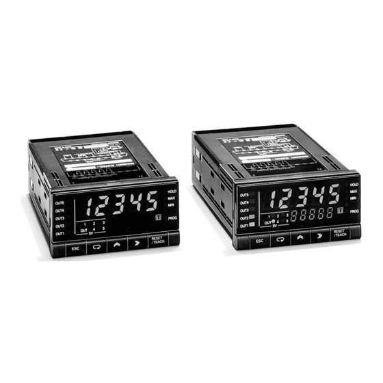
Up/Down Counting Meter
An Ideal Interface for High-Speed
Up/Down Counting and Serial
Communications
1
50-kHz input range for high-speed
signal processing
1
A wide selection of outputs: relay,
transistor, BCD, linear, or
communications
1
Prescale function available, which
displays in units of actual physical
parameters (length, volume, etc.)
1
Auxiliary power supply (12 VDC, 80 mA)
1
Banks with four set values and four
prescale values
1
Five-stage comparative outputs
available
1
NEMA4/IP66 front panel
1
UL, CSA, and CE approved
Ordering Information
To order output and communication boards, refer to the separate K31 data sheet called Output and Communication Boards . See page 155.
3 BASE UNIT
Model
Basic model
Present value LED and front-panel control
keys. Can connect to any output board or,
without an output board, can be used for
display only.
Set value LED model
Present value LED, set value LED, and front-
panel control keys. Can connect to relay,
transistor, or combination output boards.
Note: Both models must be used with an output board in order for them to operate.
9
Supply voltage
y
g
100 to 240 VAC
12 to 24 VDC
100 to 240 VAC
12 to 24 VDC
Part number
Applicable output boards
Input type
NPN/Voltage pulse
K31-C1/C2/C5
K3NC-NB1A
K31-T1/T2
K31-B2/B4
K31-L1/L2/L3/L4/L5/L6/
L7/L8/L9/L10
K31-FLK1/FLK2/FLK3/
K31 FLK1/FLK2/FLK3/
K3NC-NB2A
FLK4/FLK5/FLK6
K31-C1/C2/C3
K3NC-NB1C
K31-T1/T2
K31-B4
K31-L4/L5/L6/L9/L10
K31-FLK4/FLK5/FLK6
K31-FLK4/FLK5/FLK6
K3NC-NB2C
K3NC
PNP
K3NC-PB1A
K3NC-PB2A
K3NC-PB1C
K3NC-PB2C
1
Advertisement
Table of Contents

Related Manuals for Omron K3NC


Summary of Contents for Omron K3NC
- Page 1 Up/Down Counting Meter K3NC An Ideal Interface for High-Speed Up/Down Counting and Serial Communications 50-kHz input range for high-speed signal processing A wide selection of outputs: relay, transistor, BCD, linear, or communications Prescale function available, which displays in units of actual physical parameters (length, volume, etc.)
-
Page 2: Model Number Legend
K3NC K3NC 3 MODEL NUMBER LEGEND Base Units K3NC - 2 3 4 1, 2. Input Sensors Codes 3. Supply Voltage 4. Display NB: NPN inputs 1: 100 to 240 VAC A: Basic Model PB: PNP inputs 2: 12 to 24 VDC... - Page 3 K3NC K3NC 3 CHARACTERISTICS Input signal No-voltage contact (30 Hz max., ON/OFF pulse width: 15 ms min.) Voltage pulse (50 kHz max., ON/OFF pulse width: 9 µs min., ON voltage: 4.5 to 30 V/OFF voltage: --30 to 2 V) Open collector (50 kHz max., ON/OFF pulse width: 9 µs min.) Connectable Sensors ON residual voltage: 3 V max.
-
Page 4: Engineering Data
3 DERATING CURVE FOR SENSOR POWER SUPPLY Note: The derating curve shown is for standard installation. The derating curve depends on the mounting direction. Ambient temperature (°C) Nomenclature 3 K3NC 1. SV Display 7. Status Indicators OUT5 2. PV Display OUT4 3. -
Page 5: Operation
3 SETTING PROCEDURES The K3NC has four modes: RUN mode for normal operations, Setting mode for initial parameter input, Protect mode for lock-out configu- ration, and Maintenance mode for initializing set values. The parameters that are accessible on any individual K3NC will vary depending on the Output Board installed. -
Page 6: Terminal Arrangement
For example, the system shown in the illustration outputs 250 A linear output range can be set as required. A value pulses when the object is advanced 0.5 m. To enable the K3NC corresponding to the maximum output value and that to display PPPP.P (mm), obtain the advanced length of the... - Page 7 K3NC K3NC K3NC-NB K3NC-PB (PNP input) (NPN input/voltage pulse input) +12 V +12 V +12 V Contact NPN output sensor PNP output sensor Voltage output 3 ROTARY ENCODER CONNECTION EXAMPLE Phase A Phase B INA/INB Counts input signals. Accepts Up/Down (individual or phase difference) inputs.
- Page 8 The following table shows the time required for a K3NC in a system to go into reverse output operation after the counting value reaches the value preset with the K3NC, and is due to the output processing time of the K3NC, signal transmission time of the system, and the relay connected to the K3NC.
-
Page 9: Block Diagram
K3NC K3NC 3 INPUT MODE AND COUNTING VALUES .øã å : Up/Down B individual input .øã ä : Up/Down C phase difference input Counting Counting value value Note: 1. “B” must be larger than half the minimum signal width. If it is smaller, an error of ±1 count may occur. - Page 10 K3NC K3NC Dimensions Unit: mm (inch) 3 K3NC Panel Cutouts PV Display 14.2 45 (1.77) (3.54) (3.58) 75 min (2.95) RESET OUT5 OUT4 OUT3 120 min. OUT2 (1.69) (1.73) (1.89) (4.72) OUT1 12.4 96 (3.78) 130 (5.12) (0.49) (0.09) 112 (4.41) 70.5...
-
Page 11: Installation
Installation 3 EXAMPLE OF CONNECTION TO PROGRAMMABLE CONTROLLER FOR K3N SERIES NOTE: DIMENSIONS SHOWN ARE IN MILLIMETERS. To convert millimeters to inches divide by 25.4. OMRON ELECTRONICS, INC. OMRON CANADA, INC. One East Commerce Drive 885 Milner Avenue Schaumburg, IL 60173... - Page 12 Mouser Electronics Authorized Distributor Click to View Pricing, Inventory, Delivery & Lifecycle Information: Omron K3NC-NB2A...
Need help?
Do you have a question about the K3NC and is the answer not in the manual?
Questions and answers