Table of Contents
Advertisement
Quick Links
Advertisement
Table of Contents

Related Manuals for Omron K3HB-P


Summary of Contents for Omron K3HB-P
- Page 1 Digital Indicators K3HB-R/-P/-C User's Manual Cat. No. N136-E1-02...
- Page 3 (2) The specifications and other information contained in this manual are subject to change without notice in order to make improvements. (3) Every precaution has been taken in the preparation of this manual. Nevertheless, OMRON assumes no responsibility for errors or omissions. If you discover any problems with this manual, please notify your nearest...
- Page 4 PRODUCTS, WHETHER SUCH CLAIM IS BASED ON CONTRACT, WARRANTY, NEGLIGENCE, OR STRICT LIABILITY. In no event shall the responsibility of OMRON for any act exceed the individual price of the product on which liability is asserted. IN NO EVENT SHALL OMRON BE RESPONSIBLE FOR WARRANTY, REPAIR, OR OTHER CLAIMS...
- Page 5 Performance data given in this manual is provided as a guide for the user in determining suitability and does not constitute a warranty. It may represent the result of OMRON's test conditions, and the users must correlate it to actual application requirements. Actual performance is subject to the OMRON Warranty and Limitations of Liability.
- Page 6 Safety Precautions ● Definition of Precautionary Information The following notation is used in this manual to provide precautions required to ensure safe usage of the product. The safety precautions that are provided are extremely important to safety. Always read and heed the information provided in all safety precautions. The following notation is used.
- Page 7 Doing so may occasionally result in minor or moderate injury due to electric shock. Do not use the equipment for measurements within Measurement Categories II, III, and IV for K3HB-R, K3HB-P, and K3HB-C (according to IEC61010-1). Doing so may occasionally cause unexpected operation, resulting in minor or moderate injury, or damage to the equipment.
- Page 8 CAUTION Make sure that the product will not be adversely affected if the DeviceNet cycle time is lengthened as a result of changing the program with online editing. Extending the cycle time may cause unexpected operation, occasionally resulting in minor or moderate injury, or damage to the equipment.
- Page 9 Precautions for Safe Use (1) Do not use the product in the following locations. • Locations subject to direct radiant heat from heating equipment • Locations where the product may come into contact with water or oil • Locations subject to direct sunlight •...
- Page 10 (16) Do not connect anything to unused terminals. (17) Output turns OFF when the mode is changed or settings are initialized. Take this into consideration when setting up the control system. (18) Install an external switch or circuit breaker that complies with applicable IEC60947-1 and IEC60947-3 requirements and label them clearly so that the operator can quickly turn OFF the power.
- Page 11 ● Noise Countermeasures Do not install the product near devices generating strong high-frequency waves or surges, such as high-frequency welding and sewing machines. (1) Mount a surge suppressor or noise filter to peripheral devices generating noise, in particular, motors, transformers, solenoids, and magnet coils. Line filter Digital Indicator Digital...
- Page 12 ● Revision History The revision code of this manual is given at the end of the catalog number at the bottom left of the back cover. Cat. No. N136-E1-02 Revision code Date Pages and changes October 2004 Original production March 2005 Page 2-4: Changed “B4”...
- Page 13 About this Manual Manual Structure Preface Provides precautionary information, a manual revision history, an overview of the manual contents, information on using this manual, and other general information. Section 1 Outline Provides an overview and describes the features of the product. Section 2 Preparations Describes the mounting and wiring required before using the product.
- Page 14 ● Settings Data Notation The letters of the alphabet in settings data are displayed as shown below. ● Applicable Model Notation The following symbols are used to indicate the applicable models for specific functions. K3HB-R@@-@@@ K3HB-P@@-@@@ K3HB-C@@-@@@...
-
Page 15: Table Of Contents
Monitoring Conveyor Line Passing Time: K3HB-R ......Measuring the Operation Time of a Press: K3HB-P...... - Page 16 Contents 5.15 Holding Comparative Outputs ..........5-49 5.16 Allocating Another Output to PASS Output.
-
Page 17: Section 1 Outline
Section 1 Outline 1.1 Main Functions and Features of the K3HB ........ 1.2 Component Names and Functions of the K3HB-R/P....1.3 Component Names and Functions of the K3HB-C ....1.4 Internal Block Diagram .............. -
Page 18: Main Functions And Features Of The K3Hb
Functions of the K3HB-R Functions of the K3HB-P Functions of the K3HB-C The K3HB-R has the following The K3HB-P has the following The K3HB-C has the following six functions for reading and six functions for reading and three functions for reading displaying input pulses. - Page 19 1.1 Main Functions and Features of the K3HB Outputs Comparative output pattern Hysteresis Output refresh stop The comparative output Prevents comparative output Holds the output status when pattern can be selected as chattering when the comparative results outputs standard output, zone output, measurement value fluctuates other than PASS turn ON.
- Page 20 Section 1 Outline Other Max/Min hold Bank selection Bank copy Holds the maximum and Eight comparative set value Any bank setting can be minimum measurement banks can be selected using copied to all banks. values. the keys on the front of the Unit or by external inputs.
-
Page 21: Component Names And Functions Of The K3Hb-R/P
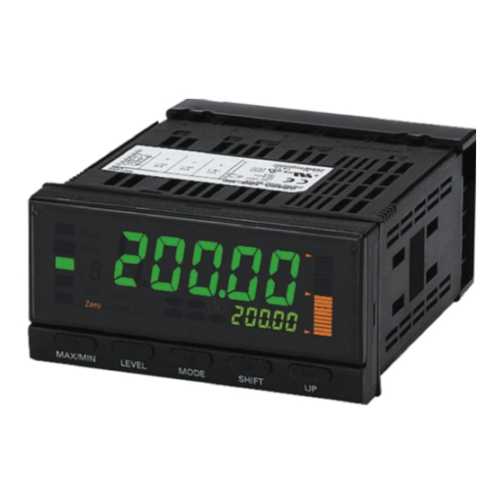
1.2 Component Names and Functions of the K3HB-R/P 1.2 Component Names and Functions of the K3HB-R/P Level/bank display Max/Min status PV display Position meter Comparative output status Status indicators SV display SV display status LEVEL Key SHIFT Key UP Key MAX/MIN Key MODE Key Name... -
Page 22: Component Names And Functions Of The K3Hb-C
Section 1 Outline 1.3 Component Names and Functions of the K3HB-C Level/bank display Max/Min status PV display Position meter Comparative output status Status indicators SV display SV display status LEVEL Key SHIFT Key UP Key MAX/MIN Key MODE Key Name Function PV display Displays PVs, maximum values, minimum values, parameter names, and... -
Page 23: Internal Block Diagram
1.4 Internal Block Diagram 1.4 Internal Block Diagram Waveform Pulse input Pulse input Keys shaping circuit circuit EEPROM Indications Input circuit Drive Transistor Drive BCD I/O Output circuit circuit output circuit Transistor output circuit Micro- computer Drive Digital input Waveform Event input Relay output circuit... - Page 24 Section 1 Outline...
-
Page 25: Section 2 Preparations
Section 2 Preparations 2.1 Mounting ..................2.2 Using I/O.................. -
Page 26: Mounting
Section 2 Preparations 2.1 Mounting ■ External Dimensions 101.2 Character size for main display (mm) PV display SV display 95 (DeviceNet models: 97) ■ Panel Cutout Dimensions 120 min. +0.8... - Page 27 2.1 Mounting ■ Mounting Method Insert the K3HB into the mounting cutout in the panel. Insert watertight packing around the Unit to make the mounting watertight. Watertight packing Insert the adapter into the grooves on the left and right sides of the rear case and push until it reaches the panel and is fixed in place.
-
Page 28: Using I/O
HDR-E50MAG1 Sensor power supply Sensor power supply + (HONDA TSUSHIN KOGYO CO., LTD.) communications Special Cable (Sold separately) K32-BCD (OMRON) (HDR-E50MAG1 with 0.3-m cable) HOLD (CMP) 1: V (Power supply cable: Black) 2: CAN L (Communications cable: Blue) 3: Shield... - Page 29 An SELV power supply has double or reinforced insulation between the input and output, an output voltage of 30 V rms and 42.4 V peak, and is 60 VDC or less. Recommended Power Supply: S8VS-06024@ (from OMRON) ● Sensor Power Supply The sensor power can be supplied from terminals B5 and B6.
- Page 30 Section 2 Preparations ● Linear Outputs Linear currents and voltages are output between terminals B1 to B2 and between B3 to B4. Connect a load within the specified range. Linear output Circuit Diagrams Linear voltage output 5 k min. Linear current output min.
- Page 31 2.2 Using I/O ● Comparative Outputs Comparative outputs are output to terminals B1 to B3 and C1 to C6. Connect loads within specifications. The electrical life expectancy of the relays is 100,000 operations. K3HB-C outputs are enclosed in parentheses (OUT*). Circuit Diagrams Contact Outputs <K34-C1>...
- Page 32 Section 2 Preparations Transistor Outputs <K34-T1> NPN Output Models 8.2 Ω HH (OUT5) 8.2 Ω H (OUT4) 8.2 Ω PASS (OUT3) 8.2 Ω L (OUT2) 8.2 Ω LL (OUT1) <K34-T2> PNP Output Models 8.2 Ω HH (OUT5) 8.2 Ω H (OUT4) 8.2 Ω...
- Page 33 3: HOLD 4: RESET 5: COMPENSATION 6: COM 7: BANK4 8: BANK2 9: BANK1 10: COM Applicable connector: XG4M-1030 (OMRON) Circuit Diagrams <K35-1><K35-2> NPN Input Models BANK (1,2,4) 12 V S-TMR: D2 HOLD: D3 RESET: D4 COMPENSATION: D5 4.7 KΩ...
- Page 34 Section 2 Preparations ● Pulse Inputs Open Collector Inputs Input the signals to be measured. The following diagram shows the inputs capable of being measured by each model. Note: E3 and E6, as well as B6 are internally connected. Circuit Diagram 12 V E2, E5 510 Ω...
- Page 35 2.2 Using I/O Voltage Pulse Inputs Input the signals to be measured. The following diagram shows the inputs capable of being measured by each model. Voltage Voltage Note: E3 and E6, as well as B6 are internally connected. Circuit Diagram 12 V 510 Ω...
- Page 36 Section 2 Preparations PNP Inputs Input the signals to be measured. The following diagram shows the inputs capable of being measured by each model. Note: E3 and E6, as well as B5 are internally connected. Circuit Diagram E2, E5 700 Ω 510 Ω...
-
Page 37: Section 3 Basic Application Methods
3.1 Monitoring Roller Speed: K3HB-R ..........3.2 Monitoring Conveyor Speed Difference: K3HB-R ...... 3.3 Monitoring Conveyor Line Passing Time: K3HB-R ....3.4 Measuring the Operation Time of a Press: K3HB-P ....3.5 Measuring Workpiece Passing Time between Points A and B: K3HB-P.................. -
Page 38: Monitoring Roller Speed: K3Hb-R
Section 3 Basic Application Methods 3.1 Monitoring Roller Speed: K3HB-R Advantages of Using the K3HB-R • Monitors roller speed by using a proximity sensor to detect the teeth on a gear attached to the end of the roller. • Outputs four comparison levels corresponding to the roller speed: LL, L, H, and HH. - Page 39 3.1 Monitoring Roller Speed: K3HB-R ■ Settings for the K3HB-R RUN Level Parameter Characters Remarks value 3400 Comparative ✽ set value HH Control example for the following 3200 Comparative settings: ✽ set value H HH alarm: 3,400 rpm H alarm: 3,200 rpm Comparative ✽...
-
Page 40: Monitoring Conveyor Speed Difference: K3Hb-R
Section 3 Basic Application Methods 3.2 Monitoring Conveyor Speed Difference: K3HB-R Advantages of Using the K3HB-R • Monitors differences in the speeds of conveyors using two 60- pulse/rotation NPN open collector rotary encoders. • Outputs four comparison levels corresponding to the conveyor speed: LL, L, H, and HH. - Page 41 3.2 Monitoring Conveyor Speed Difference: K3HB-R ■ Settings for the K3HB-R RUN Level Parameter Characters Remarks value Comparative ✽ set value HH Control example for the following Comparative settings: ✽ set value H HH alarm: 100 rpm H alarm: 50 rpm Comparative ✽...
- Page 42 Section 3 Basic Application Methods Display Adjustment Level Parameter Characters Set value Remarks color grn-r Display color PASS range: Green, selection LL, L, H, and HH ranges: disp Display value Present value selection pos-t Position meter Deviation display type pos-h Position meter upper limit Full-scale...
-
Page 43: Monitoring Conveyor Line Passing Time: K3Hb-R
3.3 Monitoring Conveyor Line Passing Time: K3HB-R 3.3 Monitoring Conveyor Line Passing Time: K3HB-R Advantages of Using the K3HB-R • Displays the passing time to tenths of a second (00.0 s) using a rotary encoder that outputs 100 pulses/rotation. • The prescale value is obtained using the following formula, assuming a roller circumference (πd) of 0.125 m and processing length of 5 m. - Page 44 Section 3 Basic Application Methods ■ Settings for the K3HB-R RUN Level Parameter Characters Remarks value 60. 0 Comparative ✽ set value H 10. 0 Comparative ✽ set value L ✽ Check on the status displays. Initial Setting Level ( Parameter Characters Set value Remarks...
-
Page 45: Measuring The Operation Time Of A Press: K3Hb-P
Advantages of using the K3HB-P • Sensor ON time is measured using a through-beam photoelectric sensor. • Displays the measurement value to tenths of a second (00.0 s) with the display unit of the K3HB-P set to seconds. K3HB-P Connections Diagram K3HB-P... - Page 46 Section 3 Basic Application Methods ■ Settings for the K3HB-P RUN Level Parameter Characters Remarks value 45. 0 Comparative ✽ set value H 35. 0 Comparative ✽ set value L ✽ Check on the status displays. Initial Setting Level (...
-
Page 47: Measuring Workpiece Passing Time Between Points A And B: K3Hb-P
3.5 Measuring Workpiece Passing Time between Points A and B: K3HB-P 3.5 Measuring Workpiece Passing Time between Points A and B: K3HB-P Advantages of Using the K3HB-P • Measures the time from when sensor A turns ON until sensor B turns ON. - Page 48 Section 3 Basic Application Methods ■ Setting for the K3HB-P RUN Level Parameter Characters Remarks value 45. 0 Comparative ✽ set value H 35. 0 Comparative ✽ set value L ✽ Check on the status displays. Initial Setting Level (...
-
Page 49: Measuring The Feed Length Of A Sheet: K3Hb-C
3.6 Measuring the Feed Length of a Sheet: K3HB-C 3.6 Measuring the Feed Length of a Sheet: K3HB-C Advantages of using the K3HB-C • Displays the measurement value to tenths of a millimeter (0000.0 mm) using a rotary encoder that outputs 250 pulses to measure a feed length of 0.5 m. - Page 50 Section 3 Basic Application Methods ■ Setting for the K3HB-C RUN Level Parameter Characters Remarks value 500. 0 Comparative set ✽ value OUT1 700. 0 Comparative set ✽ value LOUT2 ✽ Check on the status displays. Initial Setting Level ( Parameter Characters Set value Remarks...
-
Page 51: Counting The Number Of Workpieces: K3Hb-C
3.7 Counting the Number of Workpieces: K3HB-C 3.7 Counting the Number of Workpieces: K3HB-C Advantages of Using the K3HB-C • Detects and counts workpieces on a conveyor. • Using the prescale value banks, two units can be counted as a single workpiece, 4 units can be counted as a single workpiece, etc. - Page 52 Section 3 Basic Application Methods ■ Settings for the K3HB-C Advanced Function Setting Level ( Parameter Characters Set value Remarks bnk-c Bank Event inputs selection *The Setting Level Protect parameter (set.pt) must be set to 0 (0), and the Move to Advanced Function Setting Level parameter (amov) to −0169 (-0169) to enable moving to the advanced function setting level.
- Page 53 3.7 Counting the Number of Workpieces: K3HB-C Comparative Set Value Level Parameter Characters Set value Remarks sv. bnk 1, 2 Comparative set value banks Bank 0 or bank 1 (See note.) sv0. o1 Comparative set value 0 OUT1 sv1. o1 Comparative set value 1 OUT1...
- Page 54 Section 3 Basic Application Methods 3-18...
-
Page 55: Section 4 Initial Setup
Section 4 Initial Setup 4.1 Initial Setup Example for the K3HB-R........4.2 Initial Setup Example for the K3HB-P ........4.3 Initial Setup Example for the K3HB-C........ -
Page 56: Initial Setup Example For The K3Hb-R
Section 4 Initial Setup 4.1 Initial Setup Example for the K3HB-R The initial setup is explained in the following example. Settings Example • A proximity sensor that outputs eight pulses per rotation is used to detect the teeth on a gear and the rotation speed of the roller is displayed in rpm. - Page 57 4.1 Initial Setup Example for the K3HB-R D Set the prescale value. ax” to “0 1250” and press the M [MODE] Key. 1. Set the prescale AX “ps ay” to “. 10 00” and press the M [MODE] Key. 2. Set the prescale AY “ps E Set the decimal point position.
-
Page 58: Initial Setup Example For The K3Hb-P
Section 4 Initial Setup 4.2 Initial Setup Example for the K3HB-P The initial setup is explained in the following example. Settings Example The passing speed is displayed in m/s when the distance between A and B is 5 m. • If the measurement value goes above 0.700, comparative output H turns ON. - Page 59 4.2 Initial Setup Example for the K3HB-P D Set the prescale value. ax” to “8 3333” and press the M [MODE] Key. 1. Set the prescale AX “ps ay” to “10 -2” and press the M [MODE] Key. 2. Set the prescale AY “ps E Set the decimal point position.
-
Page 60: Initial Setup Example For The K3Hb-C
Section 4 Initial Setup 4.3 Initial Setup Example for the K3HB-C The initial setup is explained in the following example. Settings Example The feed length is displayed to tenths of a millimeter (0000.0mm) using a rotary encoder that outputs 250 pulses per rotation to measure a feed length of 0.5 m. - Page 61 4.3 Initial Setup Example for the K3HB-C D Set the prescale value. ax” to “2 0000” and press the M [MODE] Key. 1. Set the prescale AX “ps ay” to “10 00” (default value) and press the M 2. Set the prescale AY “ps [MODE] Key.
- Page 62 Section 4 Initial Setup...
-
Page 63: Section 5 Functions And Operations
Section 5 Functions and Operations Knowledge Required for Setting Parameters........5.1 Setting the Function for the K3HB-R.......... 5.2 Setting the Function for the K3HB-P.......... 5-16 5.3 Setting the Function for the K3HB-C.......... 5-23 5.4 Setting Input Types ..............5-27 5.5 Setting Prescale Values ............. - Page 64 Section 5 Functions and Operations Knowledge Required for Setting Parameters ■ About Levels Levels are groups of parameters. Levels for the K3HB are classified as follows: Important Depending on the level, measurements may continue Measurement to be executed or may be Level Function operations...
- Page 65 Knowledge Required for Setting Parameters To change a parameter, move to the level where that parameter is found. The current level is shown on the bank/level display when moving between levels. Level/bank Level display Protect level 0 to 7 RUN level (Lights only when banks are used.) Not lit or Adjustment level Initial setting level...
- Page 66 Section 5 Functions and Operations ■ Moving between Levels Power ON Always displayed, regardless of model or settings. May not be displayed, depending on the model or settings. Level change Less than 3 s min. Protect Adjustment 1 s min. Measurement starts.
- Page 67 Knowledge Required for Setting Parameters Procedure The Setting Level Protect setting must be set to 0 (set.pt=0) to enable moving to the advanced function setting level. Refer to "5.34 Limiting Key Operations" (P.5-84) for the procedure to release protection. A Move to the initial setting level, press the M [MODE] Key several times to display the “amov”...
- Page 68 Section 5 Functions and Operations ■ Monitoring and Changing Set Values The value set for a parameter is called the “set value.” Set values can be numerals or characters. When the SV display is lit, it is called the “monitor status.” When the SV display is flashing, it is called the “change status.”...
- Page 69 Knowledge Required for Setting Parameters Some comparative set values may not be displayed, depending on the relay/transistor output specifications and settings. Refer to the parameter setting procedures for information on how to change comparative set values. *Outputs of the K3HB-C are given in parentheses. Power ON Power ON Comparative...
- Page 70 Section 5 Functions and Operations Parameter Setting Procedure A Press the M [MODE] Key several times to display the 123.4 comparative set value to be changed. :9999 • One of the values between HH and LL will flash, according to the displayed comparative set value.
-
Page 71: Setting The Function For The K3Hb-R
5.1 Setting the Function for the K3HB-R 5.1 Setting the Function for the K3HB-R Initial setting level The K3HB-R supports six different measurement operations. Explanation of Functions Functions ■ F1: Rpm/Circumferential Speed Measuring Roller Measuring Motor Speed Winding Speed PASS K3HB-R K3HB-R Alarm outputs... - Page 72 Section 5 Functions and Operations N: Pulses per rotation πd: Circumferential length per rotation Example: This example shows the prescale value and the prescale set values for displaying the speed of a roller using a proximity sensor that outputs five pulses per rotation. −1 Prescale value (α) = 1/5 = 2.0 ×...
- Page 73 5.1 Setting the Function for the K3HB-R ■ F3: Error Ratio Measuring the Line Speed Error Ratio between Two Conveyors Encoder Communications output To computer Remote monitor Operation Configuration (Application) • Basic Operation The error ratio between the frequency of input A and the frequency of input B is displayed as a percentage (%).
- Page 74 Section 5 Functions and Operations ■ F4: Rotational Difference Measuring the Rpm/Circumferential Speed Difference (Absolute Difference) between Two Conveyors Encoder PASS Alarm outputs Operation Configuration (Application) • Basic Operation The difference between the speed of input A and the speed of input B is displayed.
- Page 75 5.1 Setting the Function for the K3HB-R ■F5: Flow Rate Ratio Monitoring Liquid Mixture Flow Rate Ratio Linear output Operation Configuration (Application) • Basic Operation The flow rate ratio (%) of input B is displayed on the basis of the frequency of input A and the frequency of input B.
- Page 76 Section 5 Functions and Operations ■ F6: Passing Time Measuring Conveyor Line Passing Time Distance PASS Alarm outputs Operation Configuration (Application) • Basic Operation The cycle of the input pulse (1/Hz) of input A is measured and displayed. The passing time is displayed in the desired unit by setting a prescale value.
- Page 77 5.1 Setting the Function for the K3HB-R Example: This example shows the prescale values and the prescale set values for measuring the passing time using a rotary encoder that outputs 100 pulses per rotation. Circumferential length per rotation (πd)= 0.125 mm Length of processing stage = 5 m Prescale value (α) = 5/(0.125/100) = 4,000 = 4.0000 ×...
-
Page 78: Setting The Function For The K3Hb-P
Section 5 Functions and Operations 5.2 Setting the Function for the K3HB-P Initial setting level The K3HB-P supports six different measurement operations. Explanation of Functions Function ■ F1: Passing Speed Measuring Workpiece Passing Speed between A and B Operation Configuration (Application) •... - Page 79 5.2 Setting the Function for the K3HB-P Referring to the following table, specify the prescale value corresponding to the desired display unit. Prescale value Calculated value Display unit (α) Passing speed mm/s 1000 L/60 L/60 m/min cm/s 100 L/60 cm/min...
- Page 80 Section 5 Functions and Operations *TR: Recovery Time The time required from the end of one measurement until completing preparations for the next measurement. Allow at least 1 ms. Referring to the following table, specify the prescale value corresponding to the desired display unit. Prescale value Calculated value Display unit...
- Page 81 5.2 Setting the Function for the K3HB-P ■ F4: Time Band Monitoring the ON time of a Controlling the Valve Open Time Printing Press Communications output Operation Configuration (Application) • Basic Operation The ON time T (s) of input A is displayed.
- Page 82 Section 5 Functions and Operations ■ F5: Measuring Length Measuring workpiece length Encoder To PLC Operation Configuration (Application) • Basic operation Displays the number of input A pulses while input B is ON. The measurement value can be obtained using the following formula: D = C ×...
- Page 83 5.2 Setting the Function for the K3HB-P ■ F6: Interval Measuring Slit Intervals Encoder PASS Alarm outputs Operation Configuration (Application) • Basic Operation The number of input A pulses from one input B rising edge to the next is displayed.
- Page 84 Section 5 Functions and Operations Use the following parameter to set the function. Parameter Meaning of set value func Function Passing speed func Cycle (FUNC) Time difference Time band Measuring length Interval Parameter Setting Procedure A Press the L [LEVEL] Key for at least 3 s in RUN level to move to func the initial setting level.
-
Page 85: Setting The Function For The K3Hb-C
5.3 Setting the Function for the K3HB-C 5.3 Setting the Function for the K3HB-C Initial setting level ■ F1: Individual Inputs The count in incremented on input A pulses and decremented on input B pulses. The count is incremented on the rising edge of input A and decremented on the rising edge of input B. - Page 86 Section 5 Functions and Operations ■ F2: Phase Differential Inputs This function is normally used when connected to an incremental rotary encoder. While input A is OFF, the count is decremented on the falling edge of input B and incremented on the rising edge of input B. The measurement value can be obtained using the following formula: D = C ×...
- Page 87 5.3 Setting the Function for the K3HB-C ■ F3: Pulse Counting Input Pulses are counted on the rising edge of input A. The measurement value can be obtained using the following formula: D = C × α C: Count α: Prescale value A D: Measurement value Input A HOLD...
- Page 88 Section 5 Functions and Operations Use the following parameter to set the function. func Parameter Meaning of set value value Function Individual inputs func (FUNC) Phase differential inputs Pulse counting input Parameter Setting Procedure A Press the L [LEVEL] Key for at least 3 s in RUN level to move to func the initial setting level.
-
Page 89: Setting Input Types
5.4 Setting Input Types 5.4 Setting Input Types Initial setting level Set the input type to match the connected input device. Parameter Set value Meaning of set value in-ta Input type A Open collector (NO) or in-ta voltage pulse (H) (IN-TA) Open collector (NC) or voltage pulse (L) -
Page 90: Setting Prescale Values
Prescale value Y exponent (PS.BY) (exponent) See note. ps. by Note: Not displayed on the K3HB-C or the K3HB-P. (DP) The decimal point position for scaling values depends on the decimal point position [dp] setting. Parameter Set value Meaning of set value... - Page 91 5.5 Setting Prescale Values Explanation of Functions Prescaling Prescaling enables input values to be displayed using any unit by multiplying the input pulse frequency or count by a specific coefficient. Example: This example shows the prescale value and the prescale set values for displaying the speed of a rotary encoder that outputs 500 pulses per second.
- Page 92 1 s min. Teaching Use the teaching function to set the scaling input value “ps. ax” using a real input. * The K3HB-P does not support teaching. Parameter Setting Procedure After performing step B, press the U [UP] Key. ps.ax •...
-
Page 93: Setting The Auto-Zero Time
5.6 Setting the Auto-zero Time 5.6 Setting the Auto-zero Time Input adjustment level The display is forced to zero when there is no pulse for a specific period of time. at. za at. za at. za Parameter Set value Meaning of set value = 0 . - Page 94 Section 5 Functions and Operations D Press the S [SHIFT] Key to make the SV display flash. at.za • The setting can be changed when the SV display starts to 2999.9 flash. E Use the U [UP] and S [SHIFT] Keys to change the set value. at.za 1.0000 F Press the M [MODE] Key to switch to the next parameter.
-
Page 95: Resetting Measurements
5.7 Resetting Measurements 5.7 Resetting Measurements When the RESET input turns ON or the [MAX/MIN] Key is pressed for at least 1 s, the maximum value, minimum value, and outputs are cleared. Measurement is not performed during RESET input. Max. value Min. -
Page 96: Not Performing Measurements For Set Intervals
Section 5 Functions and Operations 5.8 Not Performing Measurements for Set Intervals Advanced function setting level With this function measurement is not performed until a set time has s-tmr passed after the S-TMR input turns ON. (Timing starts at the rising edge of the S-TMR input and the PV display is “-----”... - Page 97 5.8 Not Performing Measurements for Set Intervals G Use the U [UP] and S [SHIFT] Keys to change the set value. s-tmr 10. 0 H Press the M [MODE] Key to switch to the next parameter. stdby • The set value is registered. I Press the L [LEVEL] Key for at least 1 s to return to the initial setting level.
-
Page 98: Averaging Input
Section 5 Functions and Operations 5.9 Averaging Input Input adjustment level Average processing of input values smooths the displays and outputs for inputs with extreme fluctuations, such as spike noise. Explanation of Functions Average processing There are two types of averaging: “simple” and “moving.” Select one type. The number of samples (“averaging times”) can also be specified for the input values to be averaged. - Page 99 5.9 Averaging Input • The data refresh periods when averaging is used are given by model in the following table. Set value Refresh period No averaging Every 20 ms Simple average Every 40 ms Every 80 ms Every 160 ms Every 320 ms Every 640 ms Every 1.28 s...
- Page 100 Section 5 Functions and Operations C Press the S [SHIFT] Key to make the SV display flash. avg-t smpl • The setting can be changed when the SV display starts to flash. D Use the U [UP] Key to change the average type setting. avg-t move E Press the M [MODE] Key to change to the next parameter “avg-...
-
Page 101: Changing Comparative Output Patterns
5.10 Changing Comparative Output Patterns 5.10 Changing Comparative Output Patterns Initial setting level This function compares the measurement value and comparative set out-p value and outputs the comparative result. The output pattern is set using the following parameter. (OUT-P) Parameter Set value Meaning of set value nomal... - Page 102 Section 5 Functions and Operations ● Level Outputs Measurement value Comparative set value HH Comparative set value H Comparative set value L Comparative set value LL Output HH Output H Output PASS Output L Output LL * The PASS output turns ON when any of the HH, H, L, and LL outputs turns OFF.
- Page 103 5.10 Changing Comparative Output Patterns Parameter Setting Procedure The following explanation uses the K3HB-R as an example. A Press the L [LEVEL] Key for at least 3 s in RUN level to move to the initial setting level. Displays “L 0.” 3 s min.
-
Page 104: Preventing Output Chattering
Section 5 Functions and Operations 5.11 Preventing Output Chattering Advanced function setting level Chattering of a comparative output results from drift in the measurement value near a comparative set value. Chattering can be prevented by adjusting the hysteresis value. Explanation of Functions Hysteresis Hysteresis is a range between the value for which a comparative output turns ON and the value for which the comparative output turns OFF. - Page 105 5.11 Preventing Output Chattering Hysteresis is set using the following parameter. Parameter Set value Meaning of set value 0 to 9999 Hysteresis 0 to 9,999 * (HYS) * The decimal point depends on the “decimal point position” setting. Parameter Setting Procedure A Press the L [LEVEL] Key for at least 3 s in RUN level to move to the initial setting level.
-
Page 106: Outputting For A Set Interval
Section 5 Functions and Operations 5.12 Outputting for a Set Interval Advanced function setting level The shot output function turns OFF a comparative output after a set interval after it turns ON. The following diagram shows operation when the shot output is set to 100 ms on the K3HB-R. Comparative set value H Measurement value... - Page 107 5.12 Outputting for a Set Interval Parameter Setting Procedure A Press the L [LEVEL] Key for at least 3 s in RUN level to move to the initial setting level. 3 s min. 0” is displayed on the level/bank display to indicate the initial Displays “L 0.”...
-
Page 108: Delaying Output Off Timing
Section 5 Functions and Operations 5.13 Delaying Output OFF Timing Advanced function setting level The output OFF delay function delays the OFF timing for comparative results. The shot output (shot) is given priority over the OFF delay (off-d). The OFF delay will be disabled if the shot output is set to anything other than “0,”... - Page 109 5.13 Delaying Output OFF Timing F Press the S [SHIFT] Key to make the SV display flash. off-d 0000 • The setting can be changed when the SV display starts to flash. G Use the U [UP] and S [SHIFT] Keys to change the set value. off-d 0050 H Press the M [MODE] Key to switch to the next parameter.
-
Page 110: Holding Measurement Status
Section 5 Functions and Operations 5.14 Holding Measurement Status Measurement values, maximum values, minimum values, and output status can be held while the HOLD input is ON. Comparative set value HH/H Comparative set value LL/L HOLD input Output HH/H Output LL/L •... -
Page 111: Holding Comparative Outputs
5.15 Holding Comparative Outputs 5.15 Holding Comparative Outputs Advanced function setting level The comparative output hold function holds the status of all outputs after any output except for the PASS output turns ON, i.e., it stops refreshing outputs. You can choose to stop outputs and continue measurement, or to stop both. - Page 112 Section 5 Functions and Operations D Use the U [UP] and S [SHIFT] Keys to set the password “- init 0169.” Press the M [MODE] Key to move to the advanced function setting level. f.” Displays “ f” is displayed on the level/bank display to indicate the •...
-
Page 113: Allocating Another Output To Pass Output
5.16 Allocating Another Output to PASS Output 5.16 Allocating Another Output to PASS Output Advanced function setting level The “PASS output change” parameter can be set to output a comparative output or error output from the PASS output terminal instead of outputting the PASS output. This function is valid only when there is a PASS output terminal. - Page 114 Section 5 Functions and Operations G Use the U [UP] Key to change the set value. pass H Press the M [MODE] Key to switch to the next parameter. • The set value is registered. I Press the L [LEVEL] Key for at least 1 s to return to the initial setting level.
-
Page 115: Reversing Output Logic
5.17 Reversing Output Logic 5.17 Reversing Output Logic Advanced function setting level The output logic reversal function sets the logic of comparative outputs out-n for comparative results. Operation (OUT-N) Parameter Comparative Comparative Comparative value result output status output Close alarm Output logic Open... - Page 116 Section 5 Functions and Operations G Use the U [UP] Key to change the set value. out-n H Press the M [MODE] Key to switch to the next parameter. o-stp • The set value is registered. I Press the L [LEVEL] Key for at least 1 s to return to the initial setting level.
-
Page 117: No Output Before Pass Range
5.18 No Output before PASS Range 5.18 No Output before PASS Range Advanced function setting level The standby sequence function can be used to prevent outputs from turning ON for unstable inputs after the power is turned ON. All outputs will remain OFF until the measurement value reaches the PASS value. - Page 118 Section 5 Functions and Operations E Press the M [MODE] Key several times to change the PV display stdby to “stdby.” F Press the S [SHIFT] Key to make the SV display flash. stdby • The setting can be changed when the SV display starts to flash.
-
Page 119: Performing Linear Output
5.19 Performing Linear Output 5.19 Performing Linear Output Linear output level The linear output function outputs currents or voltages proportional to measurement values as they change. Select the type of linear output. Set the maximum and minimum output measurement values to output the current or voltage for those measurement values. - Page 120 With the K3HB-P, the setting range for the linear output lower limit value and the linear output upper limit value is 0 to 99999. Input the upper and lower limits for the linear output as integer values.
- Page 121 5.19 Performing Linear Output H Press the M [MODE] Key to switch to the next parameter. lset. l :9999 I Press the S [SHIFT] Key to make the SV display flash. lset. l :9999 J Use the S [SHIFT] and U [UP] Keys to change the linear output lset.
-
Page 122: Changing The Display Refresh Period
Section 5 Functions and Operations 5.20 Changing the Display Refresh Period Display adjustment level When measurement values change rapidly, the accompanying changes in the display value can cause flickering, decreasing readability. Readability of the display can be improved in such situations by lengthening the display refresh period to suppress flickering. -
Page 123: Setting A Compensation Value For The Measurement Value
5.21 Setting a Compensation Value for the Measurement Value 5.21 Setting a Compensation Value for the Measurement Value Input adjustment level This function sets the measurement value to the compensation value on the rising edge of the COMPENSATION input signal. Compensation can be made conditional by selecting a compensation condition. - Page 124 Section 5 Functions and Operations Parameter Setting Procedure A Press the L [LEVEL] Key for at least 3 s in RUN level to move to the initial setting level. 3 s min. 0.” 0” is displayed on the level/bank display to indicate the initial Displays “...
-
Page 125: Holding Measurement Values
5.22 Holding Measurement Values 5.22 Holding Measurement Values Input adjustment level This function holds measurement values in the event of a power interruption. You can specify that measurement values be held or not held. This function can be used to control fluctuations in the measurement value even if the device momentarily stops. - Page 126 Section 5 Functions and Operations D Press the S [SHIFT] Key to make the SV display flash. memo • The setting can be changed when the SV display starts to flash. E Use the U [UP] Key to change the set value. memo F Press the M [MODE] Key to switch to the next parameter.
-
Page 127: Holding Maximum And Minimum Values
5.23 Holding Maximum and Minimum Values 5.23 Holding Maximum and Minimum Values • Each time the [MAX/MIN] Key is pressed in the RUN level, the maximum or minimum value recorded while a measurement is being performed will be displayed. Max. value Min. - Page 128 Section 5 Functions and Operations ● Maximum and Minimum Value Interruption Memory This function can be used to hold the maximum and minimum values during power interruptions. The settings are hold and don’t hold. This function enables fluctuation management using the maximum and minimum values even if the device should momentarily stop.
-
Page 129: Changing Normal Display Values To Maximum And Minimum Values
5.24 Changing Normal Display Values to Maximum and Minimum Values 5.24 Changing Normal Display Values to Maximum and Minimum Values Display adjustment level The PV display value displayed after power is turned ON, after a disp RESET input, immediately after moving to the RUN level, and immediately after automatic display return to the RUN or adjustment levels can be set to any of the following: present value, maximum (DISP) -
Page 130: Displaying/Not Displaying Comparative Set Values
Section 5 Functions and Operations 5.25 Displaying/Not Displaying Comparative Set Values Display adjustment level Comparative set values can be displayed or not displayed on the SV sv. dsp display during operation. This is set using the following parameter. (SV.DSP) Parameter Set value Meaning of set value Comparative set value not... -
Page 131: Changing Display Colors
5.26 Changing Display Colors 5.26 Changing Display Colors Display adjustment level The PV display color can be switched when the comparative result color changes from PASS to HH, H, L, or LL, or when an input error occurs during operation in RUN, adjustment, or protect levels. (COLOR) This function is called “display color selection.”... - Page 132 Section 5 Functions and Operations F Press the M [MODE] Key to switch to the next parameter. disp • The set value is registered. G Press the L [LEVEL] Key for at least 1 s to return to RUN level. 123.
-
Page 133: Using The Position Meter
*1. The decimal point depends on the “decimal point position” parameter setting. With the K3HB-P, the setting range is 0 to 99999. *2. The amount that the displayed value differs from the mid-point between the position meter upper and lower limits (the deviation) is displayed. - Page 134 Section 5 Functions and Operations Parameter Setting Procedure A Press the L [LEVEL] Key for at least 3 s in RUN level to move to the initial setting level. 3 s min. Displays “L 0.” 0” is displayed on the level/bank display to indicate the initial •...
-
Page 135: Automatic Return To Normal Display
5.28 Automatic Return to Normal Display 5.28 Automatic Return to Normal Display Display adjustment level If no keys operations are performed for a specified time in the RUN level or adjustment level, the display will automatically return to the display status activated when the power was turned ON. The time until the display returns automatically can be set and the automatic display return can be disabled through this setting. -
Page 136: Performing Output Tests
- 1 9999 to test 99999 Note: With the K3HB-P, the setting range is 0 to 99999. Parameter Setting Procedure A Press the L [LEVEL] Key for at least 3 s in RUN level to move to the initial setting level. -
Page 137: Using Prescale/Comparative Set Value Banks
5.30 Using Prescale/Comparative Set Value Banks 5.30 Using Prescale/Comparative Set Value Banks Advanced function setting level/Prescale level/Comparative set value level The K3HB has 8 banks where groups of prescale values and comparative set values can be set in advance. Prescale values and comparative set values can be changed easily by switching these banks. This function is called “bank selection.”... - Page 138 Section 5 Functions and Operations Parameter Setting Procedure A Press the L [LEVEL] Key for at least 3 s in RUN level to move to the initial setting level. 3 s min. Displays “L 0.” 0” is displayed on the level/bank display to indicate the initial •...
- Page 139 5.30 Using Prescale/Comparative Set Value Banks ■ 2. Setting Prescale Values for Each Bank Use the following parameter to set the prescale values. ps. bnk Parameter Set value Meaning of set value 0 0 0 0 0 0 . 0000 to Input A Input A prescale value (PS.BNK)
- Page 140 ∗ Bank number: 0 to 7. (SV∗L) Note: The decimal point depends on the “decimal point position” sv∗. ll parameter setting. With the K3HB-P, the setting range is 0 to 99999. ● K3HB-C (SV∗LL) * 0 to 7 Parameter Set value Meaning of set value −19999 to 99999...
- Page 141 5.30 Using Prescale/Comparative Set Value Banks D Use the U [UP] Key to select the bank to be set. sv. bnk E Press the M [MODE] Key. sv1. hh 99999 • The bank selected in step D can be set. F Press the M [MODE] Key several times to select the comparative sv1.
- Page 142 Section 5 Functions and Operations Proceed to step D to correct Proceed to step if bank copied bank parameters. comparative set value settings have been completed. N Press the L [LEVEL] Key for at least 1 s to return to RUN level. 123.
-
Page 143: Copying Bank Prescale Values
5.31 Copying Bank Prescale Values 5.31 Copying Bank Prescale Values Prescale level The bank copy function is used to specify a bank between 0 and 7 and copy copy the group of prescale values in that bank to all banks. Parameter Setting Procedure (COPY) A Press the L [LEVEL] Key for at least 3 s in RUN level to move to... -
Page 144: Copying Bank Comparative Set Values
Section 5 Functions and Operations 5.32 Copying Bank Comparative Set Values Comparative set value The bank copy function is used to specify a bank between 0 and 7 and copy copy the group of comparative set values in that bank to all banks. Parameter Setting Procedure (COPY) A Press the L [LEVEL] Key for at least 3 s in RUN level to move to... -
Page 145: Initializing All Settings
5.33 Initializing All Settings 5.33 Initializing All Settings Advanced function setting level Important * Initialization can be used to start settings over again from the default settings. Refer to "Parameter List" (P.A-8) for information on default set init values. Parameter Setting Procedure (INIT) A Press the L [LEVEL] Key for at least 3 s in RUN level to move to the initial setting level. -
Page 146: Limiting Key Operations
Section 5 Functions and Operations 5.34 Limiting Key Operations Protect level The key protect function limits level and parameter changes using key operations. There are five kinds of key protection. The parameters, settings and details on the limitations of each kind of protection are outlined below. - Page 147 5.34 Limiting Key Operations ● Max/Min Protect The following parameter limits key operations for switching and resetting maximum and minimum values. Max./min. Parameter Set value value Reset switching Enabled Enabled Max/Min protect Enabled Prohibited mm.pt Prohibited Prohibited Parameter Setting Procedure A Press the L [LEVEL] and M [MODE] Keys together for at least run.
- Page 148 Section 5 Functions and Operations 5-86...
- Page 149 Section 6 Troubleshooting 6.1 Error Displays ................6.2 Countermeasures ..............
-
Page 150: Error Displays
Displayed the first time power is turned ON after mounting a new register the new Unit configuration. Unit. disp Display error Repair is necessary. Consult your OMRON representative. Internal A SYSERR Repair is necessary. memory error message Consult your OMRON representative. -
Page 151: Countermeasures
6.2 Countermeasures 6.2 Countermeasures Symptoms Inspection details Countermeasure The display remains on “-----” Is the “startup compensation The “startup compensation after the power is turned ON. timer” setting too long? timer” can be set up to 99.9 s. Change the setting to an appropriate value. - Page 152 Section 6 Troubleshooting...
-
Page 153: Appendices
Appendices Specifications..................Model Number Structure..............Parameter List..................Parameter Display Conditions ............A-17 About Parameters ................A-23 “No-Measurement” Status ..............A-29 Forecasted Cycle Calculations ............A-30... -
Page 154: Specifications
*1 For models with DC power supply, approximately 1 A of control power supply capacity is required for each Digital Indicator. Be sure there is adequate power supply capacity when using more than one Digital Indicator. We recommend the S8VS DC Power Supply from OMRON. *2 Models with PNP inputs are also available. - Page 155 Specifications ■ Characteristics K3HB-R −19,999 to 99,999 Display range Measurement accuracy Functions F1, F6: ±0.006% rdg ±1 digit (for voltage pulse/open collector sensors) (at 23±5°C) Functions F2 to F5: ±0.02% rdg ±1 digit (for voltage pulse/open collector sensors) Measurement range Functions F1 to F6: 0.5 mHz to 50 kHz (for voltage pulse/open-collector sensors) Input signals No-voltage contact...
- Page 156 Appendices K3HB-P −19,999 to 99,999 Display range Measurement accuracy ±0.08% rdg ±1 digit (for voltage pulse/open collector sensors) (at 23±5°C) Measurement range Functions F1, F3, and F4:10 ms to 3,200 s (input pulse interval) Function F2: 20 ms to 3,200 s (input pulse interval)
- Page 157 Specifications K3HB-C −19,999 to 99,999 Display range Measurement range Functions F1, F2: ±2 gigacounts, Functions F3: 0 to 4 gigacounts Input signals • No-voltage contact (30 Hz max. with ON/OFF pulse width of 15 ms min.) • Voltage Mode Input frequency ON/OFF ON voltage OFF voltage...
- Page 158 Appendices ■ Power Supply Derating Curve for Sensor (Reference Value) Max. current (mA) Max. current (mA) −20 −10 −20 −10 Ambient temperature (°C) Ambient temperature (°C) With 12 V With 12 V With 10 V Note 1. The above values are for standard mounting. Be careful because the derating curve depends on the mounting conditions.
-
Page 159: Model Number Structure
Model Number Structure Model Number Structure Base Units with Optional Boards K3HB-@@-@@@ @ 1. Models by Type Code Input specifications Rotary pulse indicator Time interval indicator Up/Down counting pulse indicator 2. Input Range Code Auxiliary output and external power supply specifications NPN voltage pulse input PNP input 3. -
Page 160: Parameter List
Appendices Parameter List Enter the set values before using. ● K3HB-R/P Level Parameter name Characters Setting range Characters Initial value Decimal point Unit value Version Status −19999 to 99999 Measurement value −19999 to 99999 Max. value −19999 to 99999 Min. value run.pt 0 to 2 RUN/adjustment... - Page 161 Parameter List Level Parameter name Characters Setting range Characters Initial value Decimal point Unit value Comparative set value s?.dsp OFF, ON off, on display d.ref off, 0. 5, 1, 2, 4 Display refresh period OFF, 0.5 s, 1 s, 2 s, 4 s Display color selection color grn-r, grn, red-g, Green (red), green, red...
- Page 162 Appendices Level Parameter name Characters Setting range Characters Initial value Decimal point Unit value Scaling Prescaling bank ps. bnk 0 to 7 0 to 7 ps0. ax 0. 0000 to 9. 9999 Prescale 0AX 0.0000 to 9.9999 1.0000 −9 to 9 Prescale 0AY ps0.
- Page 163 Parameter List Level Parameter name Characters Setting range Characters Initial value Decimal point Unit value Comparative set value s?.bnk 0 to 7 0 to 7 bank s?0.hh Comparative set value Same as measurement Same as measurement 99999 Same as measurement value value value...
- Page 164 Appendices Level Parameter name Characters Setting range Characters Initial value Decimal point Unit value Linear Linear current type lset. c 0-20 mA, 4-20 mA 0-20, 4-20 4-20 mA output lset. v 0-5, 1-5, 0-10 Linear voltage type 0-5 V, 1-5 V, 0-10 V 1-5 V Linear output upper lset.
- Page 165 Parameter List ● K3HB-C Level Parameter name Characters Setting range Characters Initial value Decimal point Unit value Version Status −19999 to 99999 Measurement value −19999 to 99999 Max. value −19999 to 99999 Min. value run.pt 0 to 2 RUN/adjustment 0 to 2 protect Setting level protect set.pt...
- Page 166 Appendices Level Parameter name Characters Setting range Characters Initial value Decimal point Unit value Scaling Prescaling bank ps. bnk 0 to 7 0 to 7 ps0. ax 0. 0000 to 9. 9999 Prescale 0X 0.0000 to 9.9999 1.0000 −9 to 9 Prescale 0Y ps0.
- Page 167 Parameter List Level Parameter name Characters Setting range Characters Initial value Decimal point Unit value −19999 to 99999 Compara- Comparative set value s?2.o2 :9999 to 99999 99999 Conforms to decimal tive set point position. value dis- s?2.o1 −19999 to 99999 :9999 to 99999 Comparative set value 99999...
- Page 168 Appendices Level Parameter name Characters Setting range Characters Initial value Decimal point Unit value Advanced Set value initialization init OFF, ON off, on function off-d 0 to 1999 Output OFF delay 0 to 1999 settings Shot output shot 0 to 1999 0 to 1999 out-n n-o, n-c...
-
Page 169: Parameter Display Conditions
Parameter Display Conditions Parameter Display Conditions ● K3HB-R/P Level Parameter Char- <1> <C1> <C2> <T1> <BCD> <CPA> <L1A> <L2A> <FLK1A> <DRT> Setting name acters <2> <T2> <CPB> <L1B> <L2B> <FLK1B> Conditions <3> <FLK2A> <4> <FLK2L run. pt Protect RUN/adjust- ment protect set. - Page 170 Appendices Level Parameter Char- <1> <C1> <C2> <T1> <BCD> <CPA> <L1A> <L2A> <FLK1A> <DRT> Setting name acters <2> <T2> <CPB> <L1B> <L2B> <FLK1B> Conditions <3> <FLK2A> <4> <FLK2L avg-t × Input Average type adjust- avg-n × Averaging ment times at. za ×...
- Page 171 Parameter Display Conditions Level Parameter Char- <1> <C1> <C2> <T1> <BCD> <CPA> <L1A> <L2A> <FLK1A> <DRT> Setting name acters <2> <T2> <CPB> <L1B> <L2B> <FLK1B> Conditions <3> <FLK2A> <4> <FLK2L ● ● ● ● ● sv. bnk Bank selection ≠ Compar- Comparative ative set...
- Page 172 Appendices Level Parameter Char- <1> <C1> <C2> <T1> <BCD> <CPA> <L1A> <L2A> <FLK1A> <DRT> Setting name acters <2> <T2> <CPB> <L1B> <L2B> <FLK1B> Conditions <3> <FLK2A> <4> <FLK2L init Advanced Set value initial- -function ization ● ● ● PASS output pass change ●...
- Page 173 Parameter Display Conditions ● K3HB-C Level Parameter Char- <1> <C1> <C2> <T1> <BCD> <CPA> <L1A> <L2A> <FLK1A> <DRT> Setting Conditions name acters <2> <T2> <CPB> <L1B> <L2B> <FLK1B> <3> <FLK2A> <4> <FLK2L run. pt Protect RUN/adjust- ment protect set. pt Setting level protect wt.
- Page 174 Appendices Level Parameter Char- <1> <C1> <C2> <T1> <BCD> <CPA> <L1A> <L2A> <FLK1A> <DRT> Setting Conditions name acters <2> <T2> <CPB> <L1B> <L2B> <FLK1B> <3> <FLK2A> <4> <FLK2L ps. bnk Bank selection ≠ OFF Scaling Prescaling pso. ax Bank selection ≠ OFF; * is Prescale * X (*: 0-7) the value between 0 and 7...
-
Page 175: About Parameters
About Parameters About Parameters ■ K3HB-R Power ON Initial setting Protect level level Measurement value RUN.PT: L E V E L PS.BX: run.pt FUNC: Comparative set value HH L E V E L MODE func ps.bx RUN/adjustment protect 99999 3 s min. Prescale BX Function -19999 to 99999... - Page 176 Appendices Display adjustment level Input adjustment level SV.DSP: Comparative sV.dsp AVG-T: Average type aVg-t set value display Simple average, smpl OFF, ON moving average L E V E L < < 1 s max. AVG-N: Averaging D.REF: aVg-n d.ref times 1, 2, 4, 8, 16, 32, Display refresh period 64,128, 256, 512, OFF, 0.5 s, 1 s, 2 s, 4 s...
- Page 177 About Parameters ■ K3HB-P Power ON Protect level RUN level Measurement value L E V E L RUN.PT: TIME: FUNC: time func Comparative set value HH run.pt L E V E L MODE 99999 RUN/adjustment protect 3 s min. OFF, min, h:min:s,...
- Page 178 Appendices Input adjustment level Display adjustment level MEMO: SV.DSP: Comparative sV.dsp memo Power interruption set value display memory OFF, ON L E V E L OFF, ON < 1 s max. D.REF: d.ref Display refresh period OFF, 0.5 s, 1 s, 2 s, 4 s <...
- Page 179 About Parameters ■ K3HB-C Power ON RUN level Initial setting level Protect level Measurement value RUN.PT: L E V E L FUNC: run.pt Comparative set value 5 func L E V E L MODE RUN/adjustment protect 99999 Decimal point position 3 s min.
- Page 180 Appendices Input adjustment level Display adjustment level COMPN: SV.DSP: Comparative sV.dsp compn Compensation value set value display −19,999 to 99,999 OFF, ON L E V E L < < 1 s max. COM-P: D.REF: com-p d.ref Adding with no Display refresh period none compensation condition MODE...
-
Page 181: Measurement" Status
“No-Measurement” Status “No-Measurement” Status When no measurement value has been determined, a “no- measurement” status exists. The PV display for no measurement is “- ----- ----” and all outputs are OFF. 88888 A no-measurement status occurs in the following circumstances. •... -
Page 182: Forecasted Cycle Calculations
Appendices Forecasted Cycle Calculations When the input pulse stops suddenly, forecasted cycle calculations are used to wait for the next input pulse based on frequency forecasts. During forecasted cycle calculations, the frequency is forecasted continuously for any point in time regardless of when the next input pulse is received. - Page 183 Advanced function setting level External dimensions Advanced function settings Automatic display return 5-73 Auto-zero time 5-31 Function for the K3HB-C 5-23 Averaging 5-36 Function for the K3HB-P 5-16 Averaging times 5-36 5-37 Function for the K3HB-R Averaging type 5-36 5-37 HOLD input 5-16...
- Page 184 Index Linear output Protect level 5-57 5-84 Linear output level Protection 5-84 Linear output lower limit 5-57 5-58 PV display Linear output upper limit 5-57 5-58 Linear voltage type 5-58 RESET input 5-33 A-29 Resetting measurements 5-33 Max/Min hold 5-65 RUN level MAX/MIN key RUN/adjustment protection...
- Page 186 The Netherlands IL 60173-5302 U.S.A. Tel: (31)2356-81-300/Fax: (31)2356-81-388 Tel: (1) 847-843-7900/Fax: (1) 847-843-7787 © OMRON Corporation 2004 All Rights Reserved. OMRON (CHINA) CO., LTD. OMRON ASIA PACIFIC PTE. LTD. In the interest of product improvement, Room 2211, Bank of China Tower, No.
Need help?
Do you have a question about the K3HB-P and is the answer not in the manual?
Questions and answers