Advertisement
Quick Links
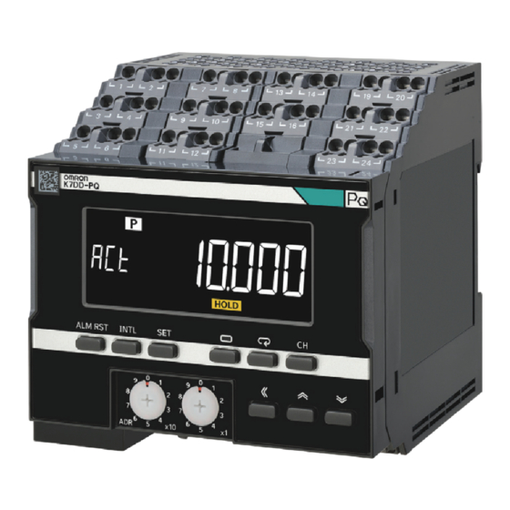
K7DD
Power Line Data Generator
EN
INSTRUCTION MANUAL
Thank you for purchasing the OMRON Product. Please observe the
following items when using the Product.
Before using the Product, thoroughly read and understand this
manual to ensure correct use.
This Product is designed for use by qualified personnel with a
knowledge of electrical systems.
Be sure to read the K7DD User's Manual (Cat. No. N233) before
using the Product.
Keep this manual in a safe location so that it is available for
reference when required.
If you have any questions, consult your dealer or OMRON
representative.
OMRON Corporation
©OMRON Corporation 2023 All Rights Reserved.
5728877-3A (Side-A)
Safety Precautions
Warning Indications
Indicates a potentially hazardous situation
CAUTION
which, if not avoided, may result in minor or
moderate injury, or property damage.
Precautions for
Precautions on what to do and what not to do to
Safe Use
ensure safe usage of the Product.
Precautions for
Precautions on what to do and what not to do to
Correct Use
ensure proper operation and performance.
Meaning of Product Safety Symbols
Electrical Shock Caution
Indicates possibility of electric shock under specific conditions.
General Prohibition
Indicates unspecified general prohibitions.
Disassembly Prohibition
Indicates prohibitions the disassembly of a device because of
the possibility of injuries due to electric shock.
General Instructions
Indicates instructions on unspecified general action.
CAUTION
Minor injury due to electric shock may occasionally occur. Do not
touch the Product except for any buttons (keys) while power is
being supplied.
Electric shock may occasionally occur. Always turn OFF the
power supplies to the measurement applications and the Product
before wiring the special CT and voltage input.
Minor electric shock, fire, or malfunction may occasionally occur.
Do not allow metal objects, conductors, or cuttings from
installation work to enter the Product.
Minor electric shock, fire, or Product failure may occasionally occur.
For the wire passing through the primary side of the special CT, be
sure to use an insulated wire with basic insulation or higher degree
of insulation. When clamping a busbar or other conductive material,
ensure basic insulation or higher level of insulation, e.g., by
covering it with an insulating material.
Minor injury due to explosion may occasionally occur. Do not use
the Product where subject to flammable or explosive gas.
Minor electric shock, fire, or malfunction may occasionally occur.
Do not disassemble, modify, or repair the Product or touch the
interior of the Product.
Property damage may occasionally occur due to ignition. Always
make sure that the wires are connected properly before turning
ON the power supply.
Property damage may occasionally occur due to ignition. When
wiring, make sure that the wiring material is properly inserted all
the way into each terminal hole of the Product.
Property damage may occasionally occur. Take appropriate
measures such as performing periodic inspection of the Product
and installing a monitoring device on a separate line.
Ratings/Characteristics
Operation power supply
100 to 240 VAC, 50/60 Hz, 24VDC
and frequency
Operating power supply
85% to 110% of the rated voltage
voltage range
Operating frequency range 45 to 65 Hz
Power consumption
K7DD-PQMA: 15.7 VA max.
K7DD-PQMD: 5.2 W max.
Ambient operating
-10 to 55°C (with no condensation or icing)
temperature
Ambient operating humidity 25% to 85% (with no condensation)
Storage temperature
-20 to 65°C
Altitude
2,000 m max.
Recommend fuse
T2A, time delay, high-breaking capacity (Operation
power supply)
Class CC, Class J, or Class T with a rated current of
7 A or less (Voltage input)
Insulation resistance
20 mΩ min.
Between the power supply terminals and the other
terminals; Between the external terminals and the
case; Between (communications terminals + trigger
input terminals + transistor output terminals) and the
other terminals; Between (voltage input terminals +
CT input terminals) and the other terminals;
Dielectric strength
2,000 V AC for 1 minute
Between the power supply terminals and the other
terminals; Between the external terminals and the
case; Between (communications terminals + trigger
input terminals + transistor output terminals) and the
other terminals; Between (voltage input terminals +
CT input terminals) and the other terminals;
Vibration resistance
Frequency 10 to 55 Hz, 0.35-mm single amplitude,
acceleration 50 m/s², 10 sweeps of 5 min each in X,
Y, and Z directions
Shock resistance
100 m/s², 3 times each in X, Y, and Z axes, 6 directions
Degree of protection
IP20
Exterior color
Black (Munsell N 1.5)
Mounting
DIN Track mounting
Weight
Approx. 360 g
Industrial electromagnetic EN/IEC61326-1
environment
Installation environment
Operation voltage: EN/IEC61010-1 Pollution Degree
2, Overvoltage category II
Measurement circuit:
EN/IEC61010-2-030 Pollution Degree 2
Measurement category conforms to Conformance to
Safety Standards.
Wiring material
Wiring
Recommended
Stripping length
Wire type
material
wires
without ferrules
2
Solid or
0.25 to 1.5 mm
Copper
Stranded wires
AWG 24 to AWG 16
Special CTs* (CTs to be connected to the Product)
Primary-side
Model numbers
Supplied cable
rated current
5 A
K6CM-CICB005
25 A
K6CM-CICB025
100 A
K6CM-CICB100
200 A
K6CM-CICB200
400 A
K6CM-CICB400
*CT (Current Transformer) is a non-contact measurement device that measures the current flowing in a wire.
Precautions for Safe Use
(1) Do not store, install, or use the Product in the following locations:
• Outdoor or locations subject to direct sunlight
• Locations subject to rain and wind damage
• Locations subject to excessive vibration or shock
• Locations subject to rapid temperature changes
• Locations prone to icing and dew condensation
• Locations subject to water or oil
• Locations subject to dust or corrosive gases (particularly sulfurizing
gases, ammonia, etc.)
• Locations subject to influence of static electricity and noise
• Locations subject to bugs and small animals
• Locations subject to electromagnetic fields
• Locations subject to a load
(2) A switch or circuit breaker should be provided close to this unit. The
switch or circuit breaker should be within easy reach of the operator,
and must be marked as a disconnecting means for this unit.
(3) Mount the Product in the correct direction for installation.
(4) Use and store the product in a location where the ambient
temperature and humidity are within the specified ranges. If
applicable, provide forced cooling.
(5) Be sure to use terminals of operation power supply carefully,
because they have hazardous voltage.
(6) Use the wire given in this manual.
(7) When wiring, wire by enough length.
(8) Make sure that the operation power supply voltage and the load
voltage and current are within the specifications of the Product.
(9) Check terminal polarity when wiring and wire all connections
correctly. Do not wire the input and output terminals incorrectly.
(10) Make sure the crimp terminals for wiring are of the specified size.
(11) Do not wire anything to the release holes.
(12) Confirm the wiring the input and output terminals correctly before
power is supplied.
(13) The terminal block may be damaged if you insert a flat-blade screwdriver
in the release hole with excessive force. When inserting a flat-blade
screwdriver into the release holes, operate with a force of 15·N or less.
(14) To prevent inductive noise, wire the lines connected to the Product
separately from power lines carrying high voltages or currents. Also,
do not wire in parallel with or on the same cables as power lines.
Other measures for reducing noise are to separate from ducts
including noisy lines.
(15) The Product may be subject to radio disturbances. Do not install the
Product near equipment that generates high frequencies or surges.
(16) The maximum terminal temperature is 65°C. Use wires with a heat
resistance of 65°C min to wire the terminals.
(17) For accurate measurement of the Product, use the range suitable for
the measurement voltage and current.
(18) Periodically check that the LCD display and LED indicators operate
correctly. Depending on the operating environment, the display or
indicators may fail due to deterioration.
(19) Do not exceed the communications distance that is given in the
specifications and use the specified communications cable. As for
the requirements on the communication distance and the cable, refer
to K7DD User's Manual (Cat. No. N233.
(20) Do not continue to use the Product if the front surface peels.
(21) The alarm output function is a function for the output of an alarm
when the set threshold value is exceeded. Do not use this function
for control, etc.
(22) Use this product inside the control panel to prevent external noise.
(23) When discarding the Product, properly dispose of it as industrial waste.
(24) Always use the special CT that is specified by OMRON' s model number.
(25) Clamp the wire of the special CT correctly. After clamping, make
sure until it clicks into place.
(26) The measurement accuracy may deteriorate due to the influence of
external magnetic fields. Install the special CT as far away as
possible from electric wires with large current flows, except for those
to be measured.
(27) Connect the special CT input and the voltage input correctly to the
same application.
(28) Install equipment so that wiring cables do not touch moving parts.
(29) Do not build a system that judges the open/closed state of the valve
based on the measurement value of the Product. A system error
may occur.
(30) If you accidentally drop the Product, the inside of the Product may
be damaged, so do not use it.
(31) Do not bend a wire past its natural bending radius or pull on it with
excessive force. Doing so may cause wire disconnection, or damage
to the terminal block.
(32) Do not wire anything to the release holes.
Precautions for Correct Use
(1) During periodic inspection, installation of an additional sensor, or
adjustment of sensor position, use the Product after ensuring that
correct operation can be performed.
(2) Do not use the product as a safety apparatus, or for the rescue of
human lives.
(3) Confirm that wire does not stick up after wiring of stranded cable.
(4) In crossover wiring, connecting more than one K7DD in parallel may
allow a large amount of current to flow. Keep the current to 10 A or
less per terminal.
(5) When wiring a ferrule terminal or single wire, push it directly into the
terminal hole.
When wiring a stranded wire, insert the wire into the terminal hole
while pushing straight along the taper of the release hole with the
recommended flat-blade screwdriver.
<Upper side>
(2)
Wire
(3)
(1)
Flat-blade screwdriver
10° to 15°
Flat-blade
screwdriver
(6) The terminal block may be damaged if specialized tool is not used.
Use a recommended flat-blade screwdriver to insert into a release
hole on the terminal block.
(7) Only a professional with an understanding of electricity and electric
devices must handle it. Read this manual carefully before using the
Product.
(8) Use the power supply voltage, input power, and other power
supplies and transformers with suitable capacities and rated outputs.
(9) Do not install the product close contact with the heating element.
(10) Use a power supply that will reach the rated voltage within 1 second
after the power is turned ON.
(11) Do not install the product near equipment that generates high
frequencies or surges.
(12) Make sure that the setting values registered in the Product match
the specifications of the load and special CT that are actually used.
(13) Do not ground the terminal on the output side of the special CT.
Failure to do so may result in unstable measurement.
(14) Do not directly clamp the special CT to the lines exceeding 600 VAC.
(15) If an error occurs during the operation of the Product, stop the operation
immediately and make suitable corrections such as replacement.
(16) Do not use any liquids such as paint thinner, similar solvents or
alcohol to clean the Product. Clean it with a soft, dry cloth.
8 mm
Model numbers
Supplied cable
K6CM-CICB005-C
K6CM-CICB025-C
Included:
K6CM-CICB100-C
Required for
Included
UL certification
K6CM-CICB200-C
K6CM-CICB400-C
Mounting to DIN Track
(1) Pull out all DIN Track mounting
hooks on the bottom of the
Product.
(3) Raise DIN Track mounting hook
and fix the Product to the DIN
Track.
• The protection provided by the device may be impaired if the device is
used in a manner that is not specified by the manufacturer.
• To use the Product, install it as an embedded device within a control panel.
• To use the special CT, install it in the same control panel as the Product
with a sufficient clearance from other devices.
• For the special CT, use one with –C suffixed to the model.
• For the operation power supply and voltage inputs, use recommended
fuses that are externally installed.
• Use the voltage and CT inputs under conditions specified for the
measurement category.
• Table 1 below shows the nominal voltage and measurement circuit connections available for each measurement category in the Main Power
Supply System Configurations. Do not use the device under conditions that exceed this category and conditions.
3-phase, 4-wire type
(neutral point
grounding)
E
PEN
CAT III
Phase voltage > 150 ≤ 300 V
Phase voltage > 150 ≤ 300 V
CAT II
Phase voltage > 300 ≤ 347 V
Connection diagrams
+
1
+
3
RS-485
4
-
Communications 1
+
5
<Lower side>
RS-485
6
-
Flat-blade screwdriver
Communications 2
7
(3)
(1)
Wire
8
External contact
25
Alarm output 1
(2)
26
27
Alarm output 2
28
29
Flat-blade
Output at Error
screwdriver
30
10° to 15°
Measurement category
The measurement category classifies the places and equipment
which you can connect to the measurement terminals, as prescribed
in EN/IEC 61010-2-030.
Each category is as follows.
CAT II :Energy-consuming equipment with an energy supply from
fixed wiring equipment (such as a power outlet)
CAT III :Equipment in fixed wiring equipment that particularly
demands equipment reliability and effectiveness
CAT IV :Equipment to use at the electrical service entry
Service entry wire
Distribution board
CAT IV
Conformance to EN/IEC Standards
This is a Class A product. In residential areas it may cause radio
interference, in which case the user may be required to take adequate
measures to reduce interference. Be sure to install it inside the control
panel.
Mounting method
(2) To mount the Product to a DIN
Track, hook the upper hook of
the Product onto the DIN Track
and press the Units in the
direction of the arrow.
(4) Install an End Plate (sold
separately) on each side of the
connected the Product without any
gap.
End Plate
End Plate
Conformance to Safety Standards
• The maximum temperature of the terminal block is 65°C. Therefore,
use wires with a rated temperature of 65°C or higher.
• Using Table 2 as a guideline, select such a wire as the case
temperature of the special CT will be 65°C or less.
• For the wire passing through the primary side of the special CT, use
an insulated wire with basic insulation or higher degree of insulation
that conforms to the rated voltage and size of the AWM (Appliance
Wiring Material) wire in Table 1.
Table 1
Measuring Voltage System Configurations
3-phase, 3-wire type
N
R
S T
MC
R
R
13
S
N
14
15
S
T
T
E
16
E
E
k
19
20
ℓ
R
R
k
21
S
22
ℓ
k
23
S
T
T
24
N
ℓ
E
E
PE
M
Phase voltage ≤ 150 V
Rated voltage and size of AWM wires: 150 V min. No size limit
Rated voltage and size of AWM wires: 600 V min. 1 AWG min.
Phase voltage ≤ 150 V
Rated voltage and size of AWM wires: 150 V min. No size limit
Rated voltage and size of AWM wires: 300 V min. No size limit
Rated voltage and size of AWM wires: 600 V min. 1 AWG min.
Special CT model
-
3-phase,
3-phase,
Single-phase,
4-wire type
3-wire type
2-wire type
K6CM-CICB005-C
2
13
R
13
R
K6CM-CICB025-C
K7DD
14
S
14
S
K6CM-CICB100-C
15
15
T
T
16
N
K6CM-CICB200-C
k
k
k
19
19
19
R
R
R
K6CM-CICB400-C
20
20
20
ℓ
ℓ
ℓ
k
k
21
21
S
T
22
22
ℓ
ℓ
이 기기는 업무용 환경에서 사용할 목적으로적합성평가를 받은 기기로서
k
가정용 환경에서사용하는 경우 전파간섭의 우려가 있습니다.
23
T
24
ℓ
Omron Companies shall not be responsible for conformity with any
standards, codes or regulations which apply to the combination of the
Product in the Buyer's application or use of the Product. At Buyer's
request, Omron will provide applicable third party certification
documents identifying ratings and limitations of use which apply to the
Product. This information by itself is not sufficient for a complete
determination of the suitability of the Product in combination with the
end product, machine, system, or other application or use. Buyer shall
be solely responsible for determining appropriateness of the particular
Product with respect to Buyer's application, product or system. Buyer
shall take application responsibility in all cases.
NEVER USE THE PRODUCT FOR AN APPLICATION INVOLVING
SERIOUS RISK TO LIFE OR PROPERTY OR IN LARGE
QUANTITIES WITHOUT ENSURING THAT THE SYSTEM AS A
WHOLE HAS BEEN DESIGNED TO ADDRESS THE RISKS, AND
THAT THE OMRON PRODUCT(S) IS PROPERLY RATED AND
INSTALLED FOR THE INTENDED USE WITHIN THE OVERALL
Internal wiring
EQUIPMENT OR SYSTEM.
CAT III
Fixed
CAT II
equipment
OMRON Corporation
Kyoto, JAPAN
Power outlet
Regional Headquarters
OMRON EUROPE B.V.
Wegalaan 67-69,2132 JD Hoofddorp
The Netherlands
Tel: (31)2356-81-300
Fax: (31)2356-81-388
OMRON ASIA PACIFIC PTE. LTD.
No. 438A Alexandra Road #05-05/08
(Lobby 2), Alexandra Technopark,
Singapore 119967
Tel: (65) 6835-3011
Fax: (65) 6835-2711
Note: Specifications subject to change without notice.
Dismounting from the DIN Track
Pull out the DIN Track mounting hook with a flat-blade
screwdriver and lift the Unit from the bottom to remove
it. The Product can be easily installed and removed if
the distance to other devices is 30 mm or more.
30 mm
above
Precautions for Correct Use
Do not open the cover. Electric shock may occur.
cover
Single-phase, 2-wire type
R
S T
MC
R
S
MC
13
R
14
15
k
19
k
19
20
ℓ
20
S
ℓ
k
E
E
21
22
M
ℓ
M
Line voltage ≤ 150 V
Line voltage > 150 ≤ 300 V
Line voltage ≤ 150 V
Line voltage > 150 ≤ 300 V
Line voltage > 300 ≤ 480 V
Table 2
Ambient operating
temperature of K7DD
Wire size
and special CT
24 AWG min.
55°C max.
(0.25 mm
2
min.)
12 AWG min.
55°C max.
(3.5 mm2 min.)
4 AWG (22 mm2)
45°C max.
2 AWG (35 mm2)
50°C max.
1 AWG min.
55°C max.
(50 mm2 min.)
2/0 AWG (70 mm2)
45°C max.
3/0 AWG min.
50°C max.
(95 mm2 min.)
3/0 AWG min. x2
40°C max.
(95 mm2 min. x2)
사 용 자 안 내 문
SUITABILITY FOR USE
Industrial Automation Company
Contact: www.ia.omron.com
OMRON ELECTRONICS LLC
2895 Greenspoint Parkway, Suite 200
Hoffman Estates, IL 60169 U.S.A.
Tel: (1) 847-843-7900
Fax: (1) 847-843-7787
OMRON (CHINA) CO., LTD.
Room 2211, Bank of China Tower,
200 Yin Cheng Zhong Road,
Pu Dong New Area, Shanghai,
200120, China
Tel: (86) 21-5037-2222
Fax: (86) 21-5037-2200
Advertisement

Subscribe to Our Youtube Channel
Related Manuals for Omron K7DD


Summary of Contents for Omron K7DD
- Page 1 (23) When discarding the Product, properly dispose of it as industrial waste. touch the Product except for any buttons (keys) while power is (24) Always use the special CT that is specified by OMRON’ s model number. being supplied. (25) Clamp the wire of the special CT correctly. After clamping, make Electric shock may occasionally occur.
- Page 2 このたびは、 オムロン製品をお買い上げいただきまして、 まことにあ ・虫や小動物がいるところ りがとうございます。 この製品のご使用に際して、 下記のことを守っ ・電界および磁界の影響を受けるところ てください。 ・荷重がかかるところ ●この説明書をよくお読みになり、 十分にご理解の上、 正しくご使用 30mm (2)作業者がすぐ電源をOFFできるようスイッチまたはサーキットブ ください。 以上 レーカを設置し、適切に表示してください。 ●この製品は電気の知識を有する専門家が扱ってください。 ●お使いになる前に、 「 形 K7DD ユーザーズマニュアル」 ④ 本製品の左右にエンドプレート (3)取り付けの際は、正しい方向に設置してください。 ③ DIN レール取り付けフックを押 (Man.No.:SGTE-726) を必ずお読みください。 (別売) を取り付けます。 し上げてレールに固定します。 (4)周囲温度および湿度は仕様範囲内で使用および保存してくださ ●この説明書はいつでも参照できるように大切に保管してください。 本製品を挟み込むように隙間なく ●使用上の注意 い。必要により、強制冷却してください。 取り付けてください。 (5)操作電源の端子は危険電圧を考慮して使用してください。...
Need help?
Do you have a question about the K7DD and is the answer not in the manual?
Questions and answers