Table of Contents
Advertisement
Quick Links
Advertisement
Chapters
Table of Contents

Related Manuals for Omron K3NR


Summary of Contents for Omron K3NR
- Page 1 Cat. No. N093-E1-1A K3NR Frequency/Rate Meter...
- Page 2 K3NR Frequency/Rate Meter Operation Manual Revised February 2001...
- Page 4 OMRON. No patent liability is assumed with respect to the use of the information contained herein. Moreover, because OMRON is constantly striving to improve its high-quality products, the information contained in this manual is subject to change without notice.
-
Page 6: Table Of Contents
TABLE OF CONTENTS PRECAUTIONS ....... . . 1 General Precautions . - Page 7 TABLE OF CONTENTS SECTION 7 BCD Output ........Connectors .
-
Page 8: About This Manual
About this Manual: This manual describes the installation and operation of the K3NR Frequency/Rate Meter and includes the sections described below. Please read this manual carefully and be sure you understand the information provided before attempting to install and operate the K3NR. -
Page 9: Precautions
This section provides precautions for using the K3NR Frequency/Rate Meter and related devices. The information contained in this section is important for the safe and reliable application of the K3NR. You must read this section and understand the information contained before attempting to set up or operate the K3NR. -
Page 10: General Precautions
OMRON representative. Be sure to read this manual before attempting to use the product and keep this manual close at hand for reference during operation. -
Page 11: Noise Prevention
Noise Prevention Section Noise Prevention Provide the following countermeasures when using the product in an environ- ment where the product is exposed to noise. • Countermeasures for protecting the product against high-frequency noise or abnormal voltages. Line filter Power Frequency/Rate input Meter + + +... -
Page 12: Introduction
SECTION 1 Introduction This section describes the functions of the K3NR. The main components are also described. Refer to the remaining sections of this manual for the operation of the K3NR and its menus in detail. Features .............. -
Page 13: Features
Prescaling The number of input pulses is converted into a desired value. Enables the K3NR to display the revolutions or rotational speed. It is necessary to multiply the number of pulses per revolution or circumference by a certain fac- tor. This factor is called the prescaling value. - Page 14 The startup compensation time parameter keeps the measurement operation from sending an unnecessary output corresponding to instantaneous, fluctuat- ing input from the moment the K3NR is turned ON until the end of the preset peri- Refer to Startup Compensation Time, page 74.
-
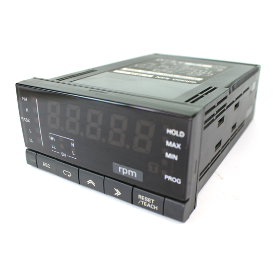
Page 15: Front Of The Meter
Setting Mode: Displays the menu, parameter, or setting value. When chang- ing a value, all digits other than those that can be set become dimmer. K3NR-jjjC Set Value LED Display Model RUN Mode: Displays the process, maximum, and minimum values. - Page 16 Front of the Meter Section 1-2 Status Indicators HOLD Indicator Lit when the HOLD input signal is ON. MAX Indicator Lit when the value displayed on the PV display is the maximum value. MIN Indicator Lit when the value displayed on the PV display is the minimum value. PROG Indicator Lit when the setting mode menu is displayed.
- Page 17 Front of the Meter Section 1-2 Up Key Used to select a parameter to be displayed for setting value change. Used to increment the current digit in the setting value by one. The value increases in the following order: 0, 1, 2, 3, 4, 5, 6, 7, 8, 9, (–1), and (–) Only the leftmost digit will be displayed if the value is set to “–1”...
-
Page 18: Rear Of The Meter
For wiring, refer to Section 2 Setup. K3NR with Relay Output Board, K31-C1, -C2, -C5 K3NR with Transistor Output Board, K31-T1, -T2 K3NR with Linear Output Board, K31-L1, -L2, -L3, -L4, -L5, -L6, -L7, -L8, -L9, -L10 K3NR with RS-485 Output Board, K31-FLK2, -FLK5 Output Board... -
Page 19: Modes
Protect mode RUN mode 1 second Setting mode RUN Mode K3NR is in RUN when the K3NR is turned ON. The K3NR in this mode provides an output signal as a result of the comparison of the measured and setting values. -
Page 20: Communications Function
Refer to Section 5 Operations in RUN Mode for RUN mode in detail. Setting Mode Values are set in the K3NR in this mode by key input or using the teaching func- tion. Refer to Section 4 Parameter Setting for value setting by key input and 6-1 Teaching Function for the teaching function in detail. -
Page 21: Setup
SECTION 2 Setup This section provides instructions required for mounting and wiring the K3NR. Mounting ............. . . -
Page 22: Mounting
Mounting Section 2-1 Mounting Dimensions All dimensions are in millimeters. PV LED Indicator Size 14.2 mm 8.2 mm Panel Cutouts +0.8 –0 75 min. +0.8 –0 120 min. Recommended panel thickness is 1 to 3.2 mm. Do not mount more than one Unit closely in the horizontal or vertical direction. Be sure to keep the distance between adjacent Units. -
Page 23: Input Block
Panel 1, 2, 3... 1. Insert the K3NR into the mounting hole on the panel. 2. Hook the fixture claws onto the side holes. 3. Mount a fixing metal to the right and left sides as shown above and while keeping them in balance, alternately tighten each screw until the ratchet be- comes idle. -
Page 24: Wiring Precautions
2-2-2 Wiring Precautions • Do not make any mistake in polarity when supply DC power to the K3NR. • Do not wire power lines alongside the signal lines of the K3NR in order to pre- vent the K3NR from noise interference. - Page 25 Input Block Section 2-2 External Signal Input HOLD Input RESET Input BANK Input Connect external signal inputs to terminals 5 through 7 and 13 through 15. Ter- minals 7 and 13 are connected to each other internally. Short-circuited together internally. Connect HOLD input to terminal 5.
-
Page 26: Output Board
K3NR with Relay Output Board, K31-C1, -C2. -C5 K3NR with Transistor Output Board, K31-T1, -T2 K3NR with Linear Output Board, K31-L1, -L2, -L3, -L4, -L5, -L6, -L7, -L8, -L9, -L10 K3NR with RS-485 Output Board, K31-FLK2, -FLK5 K3NR with BCD Output Board, K31-B2, -B4... - Page 27 Output Board Section 2-3 K3NR with RS-422 + Transistor Output Board, K31-FLK6 K3NR with RS-232C Output Board, K31-FLK1 K3NR with RS-422 Output Board, K31-FLK3...
-
Page 28: Output Board
Output Board Section 2-3 2-3-2 Relay Output Board The following figures show the connections for relay output. K3NR with 5 Relay K3NR with 3 Relay Output Boards, Output Boards, K31-C2 K31-C1 HH comparative output comparative output H comparative output PASS... -
Page 29: Transistor And Combination Output Board
Board, K31-B2 or K31-B4 Transistor Output Boards, K31-FLK4 K3NR with Linear Output Board, K31-L4, -L5, -L6, -L9, -L10 K3NR with RS-422 + 5 Transistor Output Boards, K3NR with RS-485 + 5 Relay K31-FLK6 Output Boards, K31-FLK5 HH comparative HH comparative HH comparative output... -
Page 30: Operating Modes
SECTION 3 Operating Modes This section provides information on the basic functions of each operating mode. Rotational/Circumferential Speed: f1 ......... Absolute Ratio: f2 . -
Page 31: Rotational/Circumferential Speed: F1
Rotational/Circumferential Speed: f1 Section 3-1 Rotational/Circumferential Speed: f1 Application example FUNCTION Measures the rotations of the roll. Basic Operation Multiplies the input frequency (Hz) of INA by 60 and displays the result in rpm. When the appropriate prescale value is selected, the rotational speed of the ob- ject is displayed. - Page 32 When the HOLD input is turned ON, measurement stops and the input mea- sured just before the HOLD input turned ON is held. While the HOLD input is ON, the K3NR holds display output, comparative output, and BCD output. When the comparative output from the Output Board is connected to the HOLD input terminal, the value measured immediately after the occurrence of an error can be obtained.
- Page 33 Rotational/Circumferential Speed: f1 Section 3-1 Available Functions Available functions in this mode are indicated as “Yes” in the following table. Menu Function Displayed Availability Reference Character page Max./Min. value display and reset Estimated frequency calculation sUset s.bank Set value bank no. of set values (See note 2) sU*.hh HH set value...
-
Page 34: Absolute Ratio: F2
Absolute Ratio: f2 Section 3-2 Absolute Ratio: f2 FUNCTION Operation example Measures the rotation ratio of the rolls. Basic Operation Displays the absolute ratio of the frequencies of INA and INB in percentage. Ob- tain display value D as follows: B x β... -
Page 35: Absolute Ratio: F2
When the HOLD input is turned ON, measurement stops and the input mea- sured just before the HOLD input turned ON is held. While the HOLD input is ON, the K3NR holds display output, comparative output, and BCD output. When the comparative output from the Output Board is connected to the HOLD input terminal, the value measured immediately after the occurrence of an error can be obtained. - Page 36 Absolute Ratio: f2 Section 3-2 Available Functions Available functions in this mode are indicated as “Yes” in the following table. Menu Function Displayed Availability Reference Character page Max./Min. value display and reset Estimated frequency calculation sUset s.bank Set value bank no. of set values (See note 2) (See note 2) sU*.hh...
-
Page 37: Error Ratio: F3
Error Ratio: f3 Section 3-3 Error Ratio: f3 FUNCTION Application example Measures the speed of the conveyor belts and the error ratio in the rotation of the conveyor belts. Basic Operation Displays the error ratio of the frequency of INA and INB in percentage. Obtain display value D as follows: x β... -
Page 38: Error Ratio: F3
When the HOLD input is turned ON, measurement stops and the input mea- sured just before the HOLD input turned ON is held. While the HOLD input is ON, the K3NR holds display output, comparative output, and BCD output. When the comparative output from the Output Board is connected to the HOLD input terminal, the value measured immediately after the occurrence of an error can be obtained. - Page 39 Error Ratio: f3 Section 3-3 Available Functions Available functions in this mode are indicated as “Yes” in the following table. Menu Function Displayed Availability Reference Character page Max./Min. value display and reset Estimated frequency calculation sUset s.bank Set value bank no. of set values (See note 2) sU*.hh HH set value...
-
Page 40: Rotational Difference: F4
Rotational Difference: f4 Section 3-4 Rotational Difference: f4 FUNCTION Application example Measures the rota- tional difference of the conveyor belts. Basic Operation Displays the rotational difference of INA and INB. Obtain display value D as fol- lows: x 60 x β – f x 60 x α... -
Page 41: Rotational Difference: F4
When the HOLD input is turned ON, measurement stops and the input mea- sured just before the HOLD input turned ON is held. While the HOLD input is ON, the K3NR holds display output, comparative output, and BCD output. When the comparative output from the Output Board is connected to the HOLD input terminal, the value measured immediately after the occurrence of an error can be obtained. - Page 42 Rotational Difference: f4 Section 3-4 Available Functions Available functions in this mode are indicated as “Yes” in the following table. Menu Function Displayed Availability Reference Character page Max./Min. value display and reset Estimated frequency calculation sUset s.bank Set value bank no. of set values (See note 2) sU*.hh HH set value...
-
Page 43: Flow Rate Ratio: F5
Flow Rate Ratio: f5 Section 3-5 Flow Rate Ratio: f5 FUNCTION Application example Measures the flow rate ratio of the mixture of A and B. Basic Operation From the frequency of INA and INB, displays the flow rate ratio of INB in percent- age. -
Page 44: Flow Rate Ratio: F5
When the HOLD input is turned ON, measurement stops and the input mea- sured just before the HOLD input turned ON is held. While the HOLD input is ON, the K3NR holds display output, comparative output, and BCD output. When the comparative output from the Output Board is connected to the HOLD input terminal, the value measured immediately after the occurrence of an error can be obtained. - Page 45 Flow Rate Ratio: f5 Section 3-5 Available Functions Available functions in this mode are indicated as “Yes” in the following table. Menu Function Displayed Availability Reference Character page Max./Min. value display and reset Estimated frequency calculation sUset s.bank Set value bank no. of set values (See note 2) sU*.hh HH set value...
-
Page 46: Passing Time: F6
SETTING πd = Circumferential length (m) per 1 cycle L = Processing length (m) Note The K3NR can display the hour, minute, and second. Refer to page 65 for de- tails. Example: Displaying passing time (sec) using a rotary encoder with 100 output pulses per revolution. - Page 47 When the HOLD input is turned ON, measurement stops and the input mea- sured just before the HOLD input turned ON is held. While the HOLD input is ON, the K3NR holds display output, comparative output, and BCD output. When the comparative output from the Output Board is connected to the HOLD input terminal, the value measured immediately after the occurrence of an error can be obtained.
- Page 48 Passing Time: f6 Section 3-6 Available Functions Available functions in this mode are indicated as “Yes” in the following table. Menu Function Displayed Availability Reference Character page Max./Min. value display and reset Estimated frequency calculation sUset s.bank Set value bank no. of set values (See note 2) sU*.hh HH set value...
-
Page 49: Pulse Counting: F7
Pulse counting will not start while the RESET input is ON. The accumulated value will be stored or cleared to zero when the K3NR is turned off, and depends on the setting of the power failure memory (memo) at option menu. - Page 50 Pulse Counting: f7 Section 3-7 Comparative Output With operating mode 7, comparative output L, LL, H, or HH turns ON when the measured value exceeds the set value. Refer to following chart for details. INA input RESET input Process value HH set value H set value LL set value...
- Page 51 Linear output 20 ms max. Maximum Pulse Counting Maximum pulse counting speed is the maximum speed at which the K3NR Speed can count INA input pulses accurately. If comparative output is used as con- trol output, the maximum pulse counting speed can be obtained as follows:...
- Page 52 Pulse Counting: f7 Section 3-7 Available Functions Available functions in this mode are indicated as “Yes” in the following table. Menu Function Displayed Availability Reference Character page Max./Min. value display and reset Estimated frequency calculation sUset s.bank Set value bank no. of set values (See note 2) sU*.hh HH set value...
-
Page 53: Parameter Setting
SECTION 4 Parameter Setting This section provides instructions for setting the parameters of the K3NR. Be sure to read this section before using the K3NR Frequency/Rate Meter for the first time. Overview ............. . . -
Page 54: Overview
K3NR will vary depending on the Output Board installed. Refer to Appendix D Available Parameters. • The K3NR is in RUN mode when the K3NR is turned on. Parameter settings in protect or setting mode are described below on the basis that the parameters are set for the first time. -
Page 55: Setting Mode
Setting Mode 4-2-1 Selecting Setting Mode • The K3NR in RUN mode will go into setting mode if the Mode Key is pressed for 1 s minimum. • The K3NR in setting mode will go into RUN mode if the Escape Key is pressed. -
Page 56: Menu Overview
Shift Key to shift to the setting state. The input will be updated automatically if no change is made for five seconds. 2. The K3NR stops measurement in setting mode. Some menus cannot be set according to the Output Board selected. - Page 57 Setting Mode Section 4-2 Setup menu Option menu Press the Mode Key for 1 second. Press the Mode Key for 1 second. Process time for averaging Operating mode measured value Startup compensa- Input A sensor type tion time Power failure Input B sensor type memory Auto zero time of input A...
-
Page 58: Setting Value Menu (Suset)
H set value 99,999 L set value –19999 LL set value –19999 Set the decimal point position in the prescaling menu. Refer to 6-1 Teaching Function. REFERENCE • The menu is only available for the K3NR with Comparative Output Board. MODELS... - Page 59 Setting Mode Section 4-2 SETTING Follow the steps described below to input the following. EXAMPLE Setting value bank = 2 HH setting value = “8000” H setting value = “6000” L setting value = “4000” LL setting value = “2000” Set Value LED Display Model Basic Model 1.
- Page 60 Setting Mode Section 4-2 6. Press the Up and Shift Keys to set the value to 8000. The input will be vali- dated automatically if no change is made for five seconds. The sU2.hh HH setting value of bank 2 setting will be displayed again. Note Press the Mode Key to enter the set value immediately.
- Page 61 Setting Mode Section 4-2 12. Press the Up and Shift Keys to set the value to 4000. The input will be vali- dated automatically if no change is made for five seconds. The sU2. l L set- ting value of bank 2 setting will be displayed again. Note Press the Mode Key to enter the input immediately.
-
Page 62: Prescaling Menu (Pscl)
Setting Mode Section 4-2 4-2-4 Prescaling Menu (pscl) p.bank Bank No. of Prescale ps*.ax Prescaling Value X (Mantissa) of Input A ps*.ay Prescaling Value Y (Exponent) of Input A ps*.bx Prescaling Value X (Mantissa) of Input B ps*.by Prescaling Value Y (Exponent) of Input B decp.* Decimal Point Position To display rotational speeds, circumferential speeds, or other values based on... - Page 63 Setting Mode Section 4-2 Refer to 6-1 Teaching Function. REFERENCE SETTING Follow the steps described below to input the following. EXAMPLE Operating mode = F1 Prescaling bank = OFF Prescaling value X (mantissa) of input A = 0.5000 Prescaling value Y (exponent) of input A = –1 Decimal point = jjjj.j (1st digit from the right) Set Value LED Display Model Basic Model...
- Page 64 Setting Mode Section 4-2 5. Press the Shift Key to display the set value 1.0000 for changing. The PROG indicator will flash. Set Value LED Display Model Basic Model 6. Press the Up and Shift Keys to set the value to 0.5000. The input will be vali- dated automatically if no change is made for five seconds.
- Page 65 Setting Mode Section 4-2 10. Press the Mode Key to display the decp decimal point position setting. Note If the set operating mode is F2 through F5, the ps.bx prescaling value X (mantissa) of input B setting will be displayed. Set Value LED Display Model Basic Model 11.
-
Page 66: Setup Menu (Setup)
4-2-5 Setup Menu (setup) func Operating Mode Use this menu to select the operating mode of the K3NR. All parameters will be set to default values if any change is made in this parameter except to those for the communications and protect settings. - Page 67 Setting Mode Section 4-2 3. Repeatedly press the Up Key until f4 is displayed. The displayed setting will be validated automatically if no change is made for five seconds. The func operating mode setting will be displayed again. Note Press the Mode Key to enter the displayed setting immediately. The next parameter will be displayed for setting.
-
Page 68: Sensor Type
• Specifies the type of sensors for input A and input B. • The sensor type of input B cannot be selected if the operating mode of the K3NR is set to f1 (rotational/circumferential speed) or f6 (passing time). FUNCTION •... - Page 69 Setting Mode Section 4-2 4. Press the Up and Shift Keys to display 11. The displayed value will be vali- dated automatically if no change is made for five seconds. The ina input A sensor type setting will be displayed again. Note Press the Mode Key to enter the displayed setting immediately.
-
Page 70: Auto Zero Time Of Input A X (Mantissa)
Note Auto-zero time must be longer than the value obtained by dividing one by the minimum frequency input of the K3NR. Auto-zero time must not be less than 0.1 s. If the operating mode of the K3NR is set to F7 (pulse counting), this parameter will not be available. Input type... - Page 71 Setting Mode Section 4-2 1. Press the Mode Key for more than one second while the setup setup menu 1, 2, 3... is displayed. The func operating mode setting will appear. Set Value LED Display Model Basic Model 2. Repeatedly press the Mode Key until the =ro.ax auto zero time of input A X (mantissa) setting is displayed.
- Page 72 Setting Mode Section 4-2 Note Press the Mode Key to enter the set value immediately. The auto zero time of input B X (mantissa) setting will be displayed for setting the next parameter. Set Value LED Display Model Basic Model 8.
-
Page 73: Time Unit
Setting Mode Section 4-2 time Time Unit The time unit can be selected to display the calculation results of F6 (passing time). FUNCTION Unit Display range Default scal scal –19999 to 99,999 Displayed in seconds within a range SETTING between 0 and 99,999 s. Displayed minutes within a range between 0 and 99,999 min. - Page 74 Setting Mode Section 4-2 4. Press the Up Key to display sec. The input will be validated automatically if no change is made for five seconds. The time time unit setting will be dis- played again. Note Press the Mode Key to enter the set value immediately. The next pa- rameter will be displayed for setting.
-
Page 75: Communications Unit Number
• Set a communications unit number as an identification number by which the host computer is connected to the K3NR. • If more than one K3NR is connected in parallel, make sure that each commu- FUNCTION nications unit number is unique. - Page 76 Setting Mode Section 4-2 3. Press the Shift Key to display the prior set value 00 for changing. The PROG indicator will flash. Set Value LED Display Model Basic Model 4. Press the Up and Shift Keys to set the value to 15. The input value will be validated automatically if no change is made for five seconds.
-
Page 77: Word Length
Setting Default none: None eUen eUen: Even odd: Odd This setting is available for the K3NR with the Communications Output Board. MODELS SETTING Follow the steps described below to set the following. EXAMPLE Word length: 8 bits Number of stop bits: 1... - Page 78 Setting Mode Section 4-2 2. Repeatedly press the Mode Key until the len word length setting is dis- played. Set Value LED Display Model Basic Model 3. Press the Shift Key to display the prior set value 7 for changing. The PROG indicator will flash.
- Page 79 Setting Mode Section 4-2 9. Press the Shift Key to display eUen for changing. Set Value LED Display Model Basic Model 10. Press the Up Key to display none. The setting will be validated automatically if no change is made for five seconds. The prty parity bit setting will be dis- played again.
-
Page 80: Option Menu (Opt)
The K3NR averages its measured value at regular preset intervals. Therefore, when the K3NR is used to measure the rpm of a machine, for example, the value indicated by the PV display will be stable without being influenced by the fluctua- FUNCTION tion of the input pulse intervals or the rotation of the machine. - Page 81 Setting Mode Section 4-2 SETTING Follow the steps described below to set the process time for averaging measured value EXAMPLE to 4 s. Set Value LED Display Model Basic Model 1. Press the Mode Key for more than one second while the opt option menu is 1, 2, 3...
-
Page 82: Startup Compensation Time
• The startup compensation time parameter keeps the measurement operation FUNCTION from sending an unnecessary output corresponding to instantaneous, fluctu- ating input from the moment the K3NR is turned ON until the end of the preset period. Setting range Unit Default 0.0 to 99.9... - Page 83 Setting Mode Section 4-2 2. Press the Mode Key to display the stine startup compensation time setting. Set Value LED Display Model Basic Model 3. Press the Shift Key to display the prior set value 00.0 for changing. The PROG indicator will flash. Set Value LED Display Model Basic Model 4.
-
Page 84: Power Failure Memory
Setting Mode Section 4-2 memo Power Failure Memory Retains the process value at the time of power failure if the operating mode of the K3NR is set to F7 (pulse counting). FUNCTION Setting Default Stored off: Not Stored SETTING SETTING Follow the steps described below to set on to enable power failure memory. - Page 85 Setting Mode Section 4-2 When no operation is executed for five seconds Set Value LED Display Model Basic Model 5. Press the Escape Key to display the opt option menu. Set Value LED Display Model Basic Model...
-
Page 86: Hysteresis
Hysteresis Hysteresis L setting value H comparative output L comparative output This setting is only available for the K3NR with the Comparative Output Unit. MODELS SETTING Follow the steps described below to set the hysteresis to 30. EXAMPLE Set Value LED Display Model Basic Model 1. - Page 87 Setting Mode Section 4-2 2. Repeatedly press the Mode Key until the hys hysteresis setting is displayed. Set Value LED Display Model Basic Model 3. Press the Shift Key to display the prior set value 0001 for changing. The PROG indicator will flash. Set Value LED Display Model Basic Model 4.
-
Page 88: Comparative Output Pattern
Setting Mode Section 4-2 c out Comparative Output Pattern • The pattern of HH, H, L, LL, and PASS comparative outputs is set in the option menu. • This function is not available when the operating mode is set to “F7.” FUNCTION Setting Default... - Page 89 Setting Mode Section 4-2 Level Output LL, L, H, or HH Comparative Output: Turns ON when the measured value exceeds the LL, L, H, or HH setting value. PASS Output: Turns ON when the LL, L, H, and HH comparative outputs are all OFF. HH setting value Measured value H setting value...
- Page 90 Setting Mode Section 4-2 This setting is only available for the K3NR with the Comparative Output Unit. MODELS SETTING Follow the steps described below to set the comparative output pattern to level output. EXAMPLE Set Value LED Display Model Basic Model 1.
-
Page 91: Upper Limit (H) Of Linear Output Range
Lower Limit (L) of Linear Output Range Linear output setting is made in the option menu to enable the K3NR to have voltage or current output in proportion to the change in display value. • The maximum and minimum values of linear output are set in this parameter. - Page 92 Setting Mode Section 4-2 SETTING Follow the steps described below to set the following. EXAMPLE H: 100.00 L: 0.00 (Assume that the decimal point is set between the 2nd and 3rd digit from the right in the prescale menu.) Set Value LED Display Model Basic Model 1.
- Page 93 Setting Mode Section 4-2 6. Press the Shift Key to display the prior set value 199.99 for changing. The PROG indicator will flash. Set Value LED Display Model Basic Model 7. Press the Up and Shift Keys to set the value to 000.00. The setting will be validated automatically if no change is made for five seconds.
-
Page 94: Remote/Local Programming
Section 4-2 Remote/Local Programming • The K3NR can be set to remote or local mode in the option menu. The K3NR in remote mode is operated through the host computer and the K3NR in local mode is operated through the front panel key input. - Page 95 Setting Mode Section 4-2 5. The setting will be validated automatically if no change is made for five se- conds. The aUg process time for averaging measured value setting will be displayed again. Note Press the Mode Key to enter the setting immediately. The r l re- mote/local setting will be displayed again.
-
Page 96: Protect Mode
Protect Mode 4-3-1 Selecting Protect Mode • The K3NR in RUN mode will go into protect mode if the Escape and Up Keys are pressed for more than 1 second. • The K3NR in protect mode will go into RUN mode if the Escape Key is pressed. -
Page 97: Menu Overview
All menus prohibited: 2 Security Setup menu prohibited: 1 All menu allowed: 0 No key input for 5 seconds. Note 1. The K3NR stops measurement in setting mode. 2. Some menus cannot be set due to the display type or output type selected. -
Page 98: Protect Menu (Prot)
Protect Mode Section 4-3 4-3-3 Protect Menu (prot) All Key Protect • The operation of all keys can be prohibited in the protect menu. FUNCTION Setting Default kpon: Key protect ON kpoff kpoff: Key protect OFF SETTING SETTING Follow the steps described below to set the key protect to ON. EXAMPLE Set Value LED Display Model Basic Model... -
Page 99: Setting Value Change Prohibit
Protect Mode Section 4-3 sUset Setting Value Change Prohibit • The setting value change of the K3NR in RUN mode with the front-panel key inputs can be prohibited in the protect menu. FUNCTION Setting Default kpon: Key protect ON kpoff... - Page 100 Protect Mode Section 4-3 4. Press the Up Key to display kpon. The setting will be validated automatically if no change is made for five seconds. The sUset setting value prohibit set- ting will be displayed again. Note Press the Mode Key to enter the setting immediately. The next pa- rameter will be displayed for setting.
-
Page 101: Counting Value Reset Prohibit
Section 4-3 reset Counting Value Reset Prohibit • Prohibits the counting value resetting of the K3NR when its operating mode is set to “F7” (pulse counting). • This function does not prohibit the counting value resetting of the K3NR with FUNCTION external signal input. - Page 102 Protect Mode Section 4-3 4. Press the Up Key to display kpon. The setting will be validated automatically if no change is made for five seconds. The reset counting value reset pro- hibit setting will be displayed again. Note Press the Mode Key to enter the setting immediately. The next pa- rameter will be displayed for setting.
-
Page 103: Maximum/Minimum Value Clear Prohibit
Protect Mode Section 4-3 mm.rst Maximum/Minimum Value Clear Prohibit • The resetting of maximum and minimum values with key input can be prohib- ited in the protect menu. However, the resetting of maximum and minimum values with external signal FUNCTION input is permitted. - Page 104 Protect Mode Section 4-3 4. Press the Up Key to display kpon. The setting will be validated automatically if no change is made for five seconds. The mm.rst maximum/minimum value clear prohibit setting will be displayed again. Note Press the Mode Key to enter the setting immediately. The next pa- rameter will be displayed for setting.
-
Page 105: Security
Protect Mode Section 4-3 secr Security • Settings in setting mode can be prohibited in the protect menu. • The following table shows what set values for menus can be prohibited. The default is 0. FUNCTION Set value Menu Setting value Prohibited SETTING Prescaling... - Page 106 Protect Mode Section 4-3 4. Press the Up Key to display 1. The setting will be validated automatically if no change is made for five seconds. The secr security setting will be dis- played again. Note Press the Mode Key to enter the setting immediately. The next pa- rameter will be displayed for setting.
-
Page 107: Operations In Run Mode
SECTION 5 Operations in RUN Mode This section provides instructions for operating the K3NR in RUN mode. Displaying and Changing Setting Values ........ -
Page 108: Displaying And Changing Setting Values
5-1-1 Displaying Setting Values Basic Model • When the Mode Key is pressed in RUN mode, the K3NR displays a setting val- ue on the PV display (in the order of HH, H, L, and LL). • While the setting value is displayed, the corresponding SV display status indi- cator is lit. - Page 109 6. To return to the process value display, perform one of the following. • Repeatedly press the Mode Key until the process value appears. • Leave the K3NR with no key input for five seconds.
- Page 110 Displaying and Changing Setting Values Section 5-1 SETTING EXAMPLE Set Value LED Display Follow the steps below to change the H setting value from 600 to 700 while the Model process value is displayed in RUN mode, provided that the HH setting value is already displayed on the SV display.
-
Page 111: Displaying And Resetting Of Maximum And Minimum Values
The external RESET input signal is turned ON. The K3NR receives the reset command through communications. • When the K3NR is reset, the maximum and minimum values are set to the pro- cess value. Note The K3NR cannot be reset with the RESET/TEACH Key if the maximum/mini- mum value clear prohibit is ON in protect mode. -
Page 112: External Input Signals
The bank number can be displayed on the PV or SV display by pressing the Shift Key for more than one second while the K3NR is in measurement operation. If there is no key input for three seconds, the K3NR will be in measurement opera- tion again. -
Page 113: Reset (Operating Mode F7)
5-3-4 HOLD (Operating Modes F1 to F6) • The K3NR will stop the measurement if the HOLD input is ON. • When the HOLD input is ON, the K3NR will retain the process value, output, and BCD data effective immediately before the HOLD input. -
Page 114: Hold (Operating Mode F7)
5-3-5 HOLD (Operating Mode F7) • If HOLD input is ON, the counting value is on hold. • The K3NR is in counting operation continuously while HOLD input is ON and comparative output and BCD data are available regardless of the HOLD input. -
Page 115: Useful Functions
SECTION 6 Useful Functions This section provides information on the output test and maintenance mode functions of the K3NR. Teaching Function ............ -
Page 116: Teaching Function
Section 6-1 Teaching Function • The K3NR is provided with a teaching function that can set an actual measured value as a set value without any front panel key input. This function is useful for setting parameters while checking the operating sta- tus of the K3NR. -
Page 117: Prescaling Value
3. Press the RESET/TEACH Key again to set the prescaling value. SETTING Follow the steps described below to use the teaching function to make the K3NR display EXAMPLE 60 as 100.00. Note In this example, all bank settings are disabled. - Page 118 Teaching Function Section 6-1 4. Press the Mode Key to display the ps.ay prescaling value Y (exponent) of input A setting. Note The asterisks indicate appropriate values. Set Value LED Display Model Basic Model 5. Press the Mode Key to display the decp decimal point position setting. Set Value LED Display Model Basic Model 6.
-
Page 119: Linear Output Range
6-1-3 Linear Output Range The teaching function can be also used to set the linear output range of the K3NR with the Linear Output Board. • The H and L linear output ranges can be set using the actual measured value instead of key input in the option menu. -
Page 120: Output Test
• Follow the steps described below to perform the test. 1, 2, 3... 1. While the K3NR is in RUN mode, press the Mode Key for more than one se- cond to set the K3NR to the setting mode. 2. Repeatedly press the Mode Key until the test output test setting is dis- played. -
Page 121: Maintenance Mode
K3NR in this mode are described below. 6-3-1 Maintenance Mode • The K3NR will be in maintenance mode if the Mode and Shift Keys are pressed simultaneously while the K3NR is turned on. • The K3NR in maintenance mode will go into RUN mode if the Escape Key is pressed. - Page 122 Maintenance Mode Section 6-3 4. Press the Up Key to display yes. Press the Mode Key to initialize all set val- ues. The K3NR will go into RUN mode. Set Value LED Display Model Basic Model RUN mode...
-
Page 123: Bcd Output
SECTION 7 BCD Output This section provides information on the use of the K3NR with the BCD Output Board. Connectors ............. . -
Page 124: Connectors
Connectors Section 7-1 Connectors Terminal Arrangement Terminal Signal name Signal number direction GND:VO (See note 1.) RD1-1 Output 1: Read data 10 digit RD1-2 Output 2: Read data 10 digit RD1-4 Output 4: Read data 10 digit RD1-8 Output 8: Read data 10 digit RD2-1 Output... - Page 125 Plug: XM2A-3701 (OMRON) Hood: XM2S-3711 (OMRON) The depth required for the installation of the K3NR is 200 mm min. in consider- ation of the space required by the cable. Connecting Conditions Refer to the following for the connecting conditions of each I/O. Refer to 2-3 Out- put Block for output signals HH through LL.
- Page 126 Connectors Section 7-1 Connection Example SYSMAC Programmable Controller Frequency/Rate Meter DC Input Unit 23.DSV Transistor Output Unit 240 Ω 240 Ω 240 Ω 240 Ω DC power supply Note 1. Connect RD2-1 through RD2-4, RD3-1 through RD3-4, RD4-1 through RD4-4, and RD5-1 through RD5-4 in the same way as RD1-1 through RD1-4.
-
Page 127: Timing Charts
The polarity of the data must be checked with a POLARITY signal. The polarity is positive when the POLARITY signal is OFF and negative when the POLARITY signal is ON. The K3NR in output test has test data output regardless of the type of REQ sig- nal. Operating Conditions The RUN signal is turned ON in RUN or output test. -
Page 128: Troubleshooting
SECTION 8 Troubleshooting This section provides information for troubleshooting the K3NR. Items to Be Checked First .......... -
Page 129: Items To Be Checked First
Check if there is any source of noise generation near the K3NR. err o chg o Output Error Meaning of Error The internal circuit has an error. Remedy Turn the K3NR off and on. If the output error still exists, the K3NR will need to be repaired. - Page 130 Display Section 8-2 Notice When the power is turned ON for the first time after a separately purchased Out- put Unit is mounted to the K3Nj, the following messages will be displayed. Follow the procedures below to clear the messages. chg o Meaning of Message: This message is displayed when the power is turned ON after an Output Unit is...
-
Page 131: Specifications
Appendix A Specifications Ratings Supply voltage 100 to 240 VAC (50/60 Hz); 12 to 24 VDC Operating voltage range 85% to 110% of supply voltage Power consumption (see note) 15 VA max. (max. AC load with all indicators lit) 10 W max. (max. DC load with all indicators lit) (see note) Sensor power supply 80 mA at 12 VDC±10% Insulation resistance... - Page 132 Baud rate 1,200/2,400/4,800/9,600/19,200/38,400 bps Transmission code ASCII (7-bit) Communicatio Write to K3NR Comparative set value, prescaling value, remote/local programming, reset control of maximum/minimum values, and other setting mode items excluding communications conditions. Read from Process value, comparative set value, maximum value, minimum value, model...
- Page 133 Specifications Appendix A Characteristics Input signal No-voltage contact (30 Hz max., ON/OFF pulse width: 15 ms min.) Voltage pulse (50 kHz max., ON/OFF pulse width: 9 µs min., ON voltage: 4.5 to 30 V/OFF voltage: –30 to 2 V) Open collector (50 kHz max., ON/OFF pulse width: 9 µs min.) Connectable Sensors ON residual voltage: 3 V max.
-
Page 134: B Estimated Frequency Calculation
The estimated value is 1/T3 if no pulse is detected for period T3. If P3 is detected at that time, the input frequency then is 1/T3. Therefore the K3NR produces a fast and accurate response as a result of its estimate. -
Page 135: C List Of Settings
Appendix C List of Settings Use this sheet to keep a record of set values. Menu Parameter Setting range Set value sUset s.bank Bank no. of set value (1 to 4) to be changed Setting value menu sU*.hh HH set value ( 19999 to 99999) sU*. -
Page 136: D Available Models
100 to 12 to 24 100 to 12 to 24 240 VAC 240 VAC Basic Models K3NR-NB1A K3NR-NB2A K3NR-PB1A K3NR-PB2A These models provide a present value LED and front-panel control keys. Can be connected to any Output Board, or can be used for display only without an Output Board. - Page 137 Base Units and Output Boards can be ordered individually or as sets. Refer to the Output Board Combinations table on page 133. Base Units Output Boards Base Units with Output Boards K3NR - K31 - K3NR - 2 3 4 2 3 4 1, 2.
-
Page 138: E Available Parameters
Appendix E Available Parameters Available parameters vary with the output board of the K3NR and are indicated as “YES” in the following table. K3NR-jBjA Basic Model Menu Parameter Output board C1/C2/ L1/L2/ L4/L5/ FLK1/ FLK4/ output C5/T1/T2 L3/L7/ L6/L9/ FLK2/... - Page 139 Note 1. The linear output range cannot be set with the K31-L3 and K31-L6 Output Boards. 2. The HH and LL set values cannot be set with the K31-C1. 3. The selected bank number will be displayed where an asterisk (*) appears. K3NR-jBjC Set Value LED Display Model Menu Parameter...
- Page 140 Available Parameters Appendix E Menu Menu Parameter Parameter Output board C1/C2/C5/ L4/L5/ FLK4/ T1/T2 L6/L9/ FLK5/ (note 2) FLK6 Process time for averaging measured value Option menu stine Startup compensation time memo Power failure memory Hysteresis c out Output pattern lset.h H linear output range (note 1)
-
Page 141: F Setting Examples
Setting Examples In the following example, with the K3NR, rotations (rpm) can be displayed using a rotary encoder that has 1,000 output pulses per revolution on condition that the prescaling bank is set to OFF, and the prescaling value is set to –3... -
Page 142: Index
Index default values, initializing set values, 113 absolute ratio, 25 dimensions, 12 operating mode setting, 58 display All Key Protect, setting, 90 description, 4 auto–zero time troubleshooting, 122 description, 3 setting, 62 auxiliary power supply, wiring, 14 error messages, 122 averaging measured value, description, 3 error ratio, 28 averaging measured values, setting process time, 72... - Page 143 Index linear output range, teaching, 111 local programming, setting, 86 panel cutouts, 12 parameter settings, 45 procedures, 46 parameters Maintenance mode, 9 available in each Output Board, 135 list, 131 Maintenance mode, operation, 113 parity bits, setting, 69 maximum value clear prohibit, setting, 95 PASS output, 80 maximum values, displaying and resetting, 103 passing speed, operating mode setting, 58...
- Page 144 Index stop bits, setting, 69 Security, setting, 97 sensor type, setting, 60 set value, teaching, 108 teaching, description, 3 set value menu, 50 teaching function, operation, 108 set values, 50 terminal arrangement, BCD Output Boards, 116 changing, 100 terminal arrangement displaying, 100 input block, 13 initializing, 113...
-
Page 145: Revision History
Revision History A manual revision code appears as a suffix to the catalog number on the front cover of the manual. Cat. No. N093-E1-1A Revision code The following table outlines the changes made to the manual during each revision. Page numbers refer to the previous version. - Page 146 The Netherlands Tel: (31)2356-81-300/Fax: (31)2356-81-388 OMRON ELECTRONICS LLC 1 East Commerce Drive, Schaumburg, IL 60173 U.S.A. Tel: (1)847-843-7900/Fax: (1)847-843-8568 OMRON ASIA PACIFIC PTE. LTD. 83 Clemenceau Avenue, #11-01, UE Square, 239920 Singapore Tel: (65)835-3011/Fax: (65)835-2711 OMRON CHINA CO., LTD. BEIJING OFFICE...
- Page 147 Authorized Distributor: Cat. No. N093-E1-1A Note: Specifications subject to change without notice. Printed in Japan 0201-0.5M (0198) (A)
Need help?
Do you have a question about the K3NR and is the answer not in the manual?
Questions and answers