
Subscribe to Our Youtube Channel
Related Manuals for Wohler iAM-SUM8

Summary of Contents for Wohler iAM-SUM8
-
Page 1: User Guide
Multi-Channel Audio Monitor/Mixers User Guide Part Number 821836, Revision A... - Page 2 In no event will Wohler Technologies, Inc. be liable for direct, indirect, special, incidental, or consequential damages resulting from any defect in the hardware, software, or its documentation, even if advised of the possibility of such damages.
-
Page 3: Table Of Contents
TABLE OF CONTENTS Table of Contents User Guide ..................1 TABLE OF CONTENTS ................3 Table of Contents ................... 3 CHAPTER 1: Installation ............... 7 Introduction ....................7 Overview .................... 7 Safety ......................7 Instructions ..................7 Safety Symbols ..................8 Mounting..................... - Page 4 Unit Configuration ................33 Meter Scales..................34 Phase Configuration................36 Analog Configuration ................37 System Options Menu ................. 38 Network Settings................38 System Reboot .................. 40 System Update .................. 41 Factory Reset ..................42 System Information ................43 Passcode Settings ................44 Forgotten Passcode ................
- Page 5 the web interface? This will allow us to monitor only the unmuted/solo Audio Meter channels on amplified stereo speakers connected to the Analog XLR’s......................76 Preset Replication..................77 Import/Export Presets................... 79 Export Configuration ................79 Import Configuration ................80 System .......................
- Page 6 ZMAN Session Sinks ................113 ZMAN Session Sources ...............115 ZMAN Updating .................115 APPENDIX E: API Documentation ............116 Introduction ....................116 API: Presets ....................116 Page 6 iAM-SUM...
-
Page 7: Chapter 1: Installation
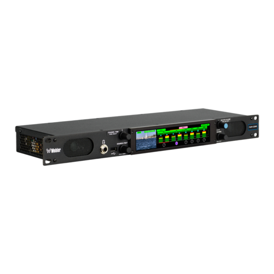
Analog inputs and outputs. Upgrade/license other signal formats and processing options, as and when needed, either initially or after purchase. Refer to the Specifications section of this manual or contact Wohler Sales for more information. The iAM-SUM is compact and simple to operate, with straightforward controls. It has a very wide format touch screen LCD display providing up to 8, 16, or 32 high resolution level meters, depending upon the model. -
Page 8: Safety Symbols
Important: By design, the supplied AC mains power cord will only plug into a three-prong grounded outlet for your safety. If the plug does not fit into the outlet, contact an electrician to replace the obsolete outlet. 7. Protect the power cord from being walked on or pinched, particularly at plug connection on the equipment and at the socket. -
Page 9: Sympathetic Vibration
proximity to the unit if this temperature is not exceeded. Otherwise, allow a 1RU (1.75”/44.45mm) space above and below the unit for air circulation. Important Heat generated by the class D power amplifiers, power supplies, and other components is vented by slots in the sides and back of the unit. -
Page 10: Ices-003
interference, in which case users will be required to correct the interference at their own expense. ICES-003 This Class A digital apparatus complies with Canadian ICES-003. Cet appareil numérique de la classe A est conforme à la norme NMB-003 du Canada. -
Page 11: Chapter 2: Local Operation
The iAM-SUM can be operated easily and simply from controls on its front panel, as described in this chapter. It may be accessed remotely in two ways, via the Wohler Web GUI for administrative purposes or by third party equipment via Application Programming Interface (API) commands. - Page 12 speaker audio is set to mute with headphone insertion, and a headphone is plugged into the Headphone Jack, the following icon will appear at the center top of the display: 4. Master Volume: This controls the speakers, the headphone and the analog outputs.
-
Page 13: Rear Panel
3. Network Port: This Ethernet port can connect to either a LAN or to a PC to let you perform administrative tasks remotely. The Wohler Web GUI is described in Chapter 4 of this manual. Third party equipment, connecting to the iAM-SUM via a LAN plugged into this port and using an API commands, can view and change product options, as well. - Page 14 enable this function. The COAX output is reclocked from the MADI source. When power to the iAM-SUM is not present, the COAX input and output are automatically connected together to allow the MADI signal to pass through. A software license must be installed for this input to function. Refer to the System Setup section in Chapter 4 to install software licenses.
- Page 15 Ethernet. You must use the MN-Set configuration software to set up this option. It is available from Wohler Technologies Technical Service. d. SMTPE 2110 Receiver: This uses Multi-Mode 850 NM, LC fiber connectors. It allows the iAM-SUM to monitor SDI audio transmitted in real time over Ethernet.
- Page 16 Option card. The source of these signals is the monitored audio channels as shown on meters 1 - 8. Tascam cables may be used, and can be purchased by contacting Wohler Sales. Refer to Figure 2-6 for the pinout of this connector.
- Page 17 Figure 2-6: Analog DB-25F Input and Output Connections Pair 1 Pair 2 Pair 3 Pair 4 15. AoIP SFP Module Cage (optional): This provides a location in which to insert the AoIP Module supplied with the OPT-DANTE (iVAM) and OPT RAVENNA 64 (iVAM) options.
-
Page 18: Sfp-2022-6 / Sfp-2110 Address Setup
To integrate it into your digital network, you need to set its address to the source to be monitored. You must use the MN-Set configuration software to set up this option. It is available from Wohler Technologies Technical Service. The procedure to accomplish this is described in the SFP-2022-6 / SFP-2110 Setup Guide (part number 821822), which is available at https://wohler.com/downloads/... -
Page 19: Channel Meter Screen
Channel Meter Screen Audio meters, as well as other indicators are displayed on the wide touchscreen LCD display in Clusters which can be set up as single channels or stereo pairs, as shown in Figure 2-8. Figure 2-8: Audio Level Meter Screen 1. -
Page 20: Operating The Monitor
Preset, press and hold the Channel Trim knob for 3 seconds. 7. Loudness Cluster Indicator: The current selected Cluster which is undergoing Loudness analysis is indicated by an orange bracket. 8. Loudness Reading: This indicator displays the Loudness of the selected Cluster. -
Page 21: Adjust The Trim Of A Cluster
Adjust the Trim of a Cluster Select the Cluster to be trimmed using one of the above methods. With the Trim Dial highlighted, rotate the Channel Trim knob. Trim can be adjusted in 1 dB steps from -60 dB to +12 dB. The relative trim level will be indicated on the Trim Dial. -
Page 22: Menu / Option Touchscreen
Menu / Option Touchscreen You may set most options or view a variety of system information using the self- contained menus. To access the Main Menu, touch the Menu button which appears on the upper left of the level meter screen or press the Source/Preset knob for 2 seconds. -
Page 23: Main Menu
Main Menu Touch the Menu button or press the Source/Preset knob to access the Main Menu. The Main Menu is shown in Figure 2-10. Figure 2-10: Main Menu Loudness Menu Touch the Loudness Menu button to reach the Loudness Menu Screen, which allows you to make a selection of either the Loudness Meter Screen or the Loudness Settings Screen. - Page 24 menu is set to Cluster Select, then rotating the Source knob will adjust the channel cluster source of the Loudness measurement. A box on the lower right of the screen shows the selected Loudness Source. Only one channel or channel pair may be selected at a time for measurement.
- Page 25 above). 3. The Maximum Loudness is the maximum calculated loudness over the program period (shown as MAX -20.1 above). 4. The Maximum True Peak Loudness is the absolute loudest peak waveform over the program period (shown as TP -20.0 above). Note: Further and more detailed descriptions of all of the above Loudness terms may be found in the ITU-R BS.1770-3 loudness standard.
-
Page 26: Loudness Settings
Loudness Settings Touch the Loudness Settings button on the Loudness Menu to display the Loudness Settings screen. This screen allows you to change between Manual and Continuous Monitoring Modes, and also to set the Alarm mode. It also provides a summary of various Loudness settings, as set in the Configuration | System Preference | Loudness Configuration tab of the Web GUI. -
Page 27: Source Select
This screen also shows sources which are unlicensed and therefore nonfunctional. These sources are shown in a gray color. To license these sources so that they may be used, contact Wohler Technologies. Figure 2-14 shows the Source Select Menu. - Page 28 Menu Back Analog Valid license is required DB25 This selection requires a license from Wohler to enable. Please call at +1-510-870-0810 or email at support@wohler.com. Thank you! Back Touch Back to return to the Source Select menu or touch Menu to return to the Main Menu.
-
Page 29: Presets
Presets Presets are pre-arranged input and monitoring setups that can be used to monitor a variety of combinations of inputs. They may be set up to allow quick and easy selection of monitoring configurations for various productions and situations. If you have not set up any Presets, use the Configure Presets page in the Web GUI to do so. - Page 30 Figure 2-17: All Presets Screen - Preset Selection To select a Preset, touch the associated button. After a quick 2-second delay, the metering screen will display the channels contained in that source. To return to the All Presets Group Selection screen instead, touch the Groups button.
-
Page 31: Preset Favorites
Preset Favorites Touch the Preset Favorites button to display the Preset Favorites screen. This shows the Presets that you have designated as Favorites. Refer to the Dashboard section of Chapter 4. Generally, these are frequently used Presets that you want to separate out from the possibly many other Presets in the system. -
Page 32: Unit Settings
Unit Settings Touching the Unit Settings selection on the Main Menu screen proceeds to the Unit Settings Menu, which contains additional menu selections. The Unit Settings Menu is shown in Figure 2-21. This is an intermediary menu which leads to other menus and screens. Figure 2-21: Unit Settings Menu Speaker Options Touching the Speaker Options selection on the Unit Settings Menu screen... -
Page 33: Unit Configuration
2. Treble: This tone control adjusts the high frequency speaker audio response from -12 dB to +12 dB. Lowering Treble compensates for high frequency pre-emphasis or removes sibilance effects. Increasing Treble will add “sizzle” to the sound and bring high-pitched sounds out of the mix. The control can be touched and moved left or right to adjust in 2 dB increments. -
Page 34: Meter Scales
the AES input. Touch the On - Off switch to change the termination setting. 3. Source Knob Selection: This setting determines the function of the Source knob on the front panel. It may be set as follows, depending upon your needs: a. - Page 35 Figure 2-25: Meter Scale Selection Table 2–4: Meter Limits and References Default Color Default Ballistics Default Bounds Scale Bottom Limit Top Limit Reference Lower Upper Float -72 dBFS 0.0 dBFS 0 dBFS = 0 dBFS -30 dBFS -20 dBFS Type I VU -53 dBr +5.5 dBr -15 dBFS = 0 dBr...
-
Page 36: Phase Configuration
Pair - 9 Pair - 10 Pair - 5 Pair - 6 Pair - 11 Pair - 12 Pair - 13 Pair - 14 Pair - 7 Pair - 8 Pair - 15 Pair - 16 iAM-SUM8 iAM-SUM16 iAM-SUM32 Page 36 iAM-SUM... -
Page 37: Analog Configuration
Analog Configuration Touching the Analog Config button in the System Options Menu displays the Analog Config screen. Contained in this menu is an Analog Reference as illustrated in Figure 2-27. The parameters set on this screen pertain to the Analog Input and Analog Output DB25 and XLR connectors on the rear panel of the iAM- SUM. -
Page 38: System Options Menu
System Options Menu Touching System Options in the Main Menu proceeds to the System Options menu, which is an intermediate menu leading to other screens. This menu is shown in Figure 2-28. Figure 2-28: System Options Menu System Options Menu Network System Settings... - Page 39 Figure 2-30: Network Configuration: Setting Change 2. Touch the digits to be entered and then touch the Enter button. The Clear button may be touched to erase any mistyped digits. 3. Now repeat steps 1 and 2 until you have replaced all of the necessary digits. 4.
-
Page 40: System Reboot
You wish to Reboot the System? If you have any doubt as to whether you should press Yes, press Back or No instead, and contact Wohler Technical Service for advice. Pressing Back or No will return you to the System Options menu. Page 40... -
Page 41: System Update
System Update Touching the System Update selection in the System Options Menu displays System Update screen as shown in Figure 2-33, showing the current software version of the product. To update the system software locally from the iAM-SUM front panel, follow the procedure in the Local Update from the Front Panel section of Appendix A. -
Page 42: Factory Reset
Mac address 28.) If you have any doubt as to whether you should press Yes, press Back or No instead, and contact Wohler Technical Service for advice. Pressing Back or No will return you to the System Options menu. -
Page 43: System Information
System Information Touching the System Details selection in the System Options menu displays the System Details screen as shown in Figure 2-35. This screen lets you view the product Serial Number, Software Version, and various other information. Figure 2-35: System Details Screen The information shown on this screen is read only and cannot be changed. -
Page 44: Passcode Settings
To prevent accidental or unauthorized changing of critical settings in some of the menus, it is possible to block or restrict access to various menus. The Wohler Web GUI can be used to limit access to the menus of your choice. Refer to Chapter 4, the Front Panel Configuration tab of System Preferences. - Page 45 When you have successfully entered the Passcode, the Passcode Settings screen will appear, as shown in Figure 2-38. Figure 2-38: Passcode Settings Screen The functions on this screen are as follows: Restricted Access: This switch will turn ON or OFF protection or blocking of any menus, except for the Passcode Settings menu, which is always Passcode protected.
-
Page 46: Forgotten Passcode
Although the Passcode should be remembered or securely noted somewhere, it can happen that it is forgotten. This can be remedied by performing a Factory Reset from the Wohler Web GUI. Unfortunately, this will also erase all of the menu settings. You may also contact Wohler Technical Service for help. -
Page 47: Chapter 3: Technical Info
CHAPTER 3: Technical Info Table 3–1: iAM-SUM Specifications Specification Values/Domains Power Requirements 100 VAC to 240 VAC ± 10%, 50/60Hz Power Consumption 65 Watts Dimensions 1.75” x 19” x 5.5” (44mm x 483mm x (H x W x D) 140mm), standard 19” rack mounting Shipping/Net Weight 8 lbs. - Page 48 Specification Values/Domains COAX (such as Belden 1694A): > 150 m Cable/Fiber Length (max) Single-mode fiber: 10 km AES Inputs 8 AES channels on HD-15 are optional AES Outputs 8 AES channels on HD-15 Upgrades Via USB or GUI web interface SDI Input Termination 75Ω...
- Page 49 Table 3–2: iAM-SUM Options Option Part # Description MADI optical fiber transceiver. Multi-Mode, LC SFP-MM-MADI- 829081 (fiber) connectors. SFP module with software Fiber activation key. MADI optical fiber transceiver. Single-Mode, SFP-SM-MADI- 829082 LC (fiber) connectors. SFP module with Fiber software activation key. 3G/HD/SD-SDI single video receiver with SFP-SDI 829089...
- Page 50 **MN-Set is configuration software that is necessary so that you can set up this module. It is available at no cost either from its manufacturer, Embrionix, or by contacting Wohler Technologies Technical Service. Table 3–3: iAM-SUM Option Cards Option...
- Page 51 Figure 3–1: iAM-SUM Block Diagram 3G-SDI Input 1 Touchscreens for Audio Meters (8, 16, or 32 Meters) 3G-SDI Input 2 Menu SDI-1 LKFS-M : -20.5 3G-SDI Output Audio from SDI 1, 2, or SFP Monitoring Input SFP Cage for Upgrades: Optional Module 2110...
-
Page 52: Chapter 4: The Iam-Sum Web Gui
CHAPTER 4: The iAM-SUM Web GUI The self-contained iAM-SUM Web GUI allows you to customize the configuration of the iAM-SUM to suit your needs. If the default configuration suits your needs and you prefer to use it that way, then you do not need to use the iAM-SUM Web GUI. The iAM-SUM Web GUI also allows you to have a remote view of the Meter Screen. -
Page 53: Network Connection
Figure 4–1: Host IP Settings Close the control panel and reboot the host computer after making an IP address change to be sure the change takes effect. Either reconnect to the installed network or continue with this direct connection to access the iAM-SUM Web GUI. -
Page 54: Network Setup
Network Setup Make network IP Address changes for the local iAM-SUM Management (MGMT) Port here. Figure 4–2: Set IP Addresses iAM-SUM The procedure for changing the IP Address information is as follows: 1. Use DHCP? Check this box if your network has a DHCP server and you want to use dynamic addressing. -
Page 55: Dashboard
Dashboard Throughout the Web GUI, pages are a click or two away using the list of selections on the left side. The Dashboard page shows all of the available Preset configurations at a glance. The iAM-SUM allows you to assign Presets to particular groups. - Page 56 In Figure 4-4, it can be seen that there are five Presets in the Operator-1 group and no Presets in the Operator-2 group. The currently selected active Preset for local operation is shown in red. In Figure 4-4, this is the Preset named SDI-1. Figure 4–4: Dashboard Preset Recall / Edit Favorite / All Group / Preset...
- Page 57 Figure 4–5: Dashboard Preset Edit The Edit options for a Preset are: 1. Delete: Remove the Preset from the system. Do Not delete the currently active Preset. 2. Rename: Rename the Preset, but keep all of its other characteristics. 3. Make Favorite: Make this Preset a favorite. This can be done for frequently used Presets.
- Page 58 Figure 4–6: Dashboard Group Edit The Edit options for a Group are as follows: 1. Delete: Delete the Group and all of the Presets it contains. 2. Rename: Rename the Group, but keep all of its other characteristics. Page 58 iAM-SUM...
-
Page 59: Audio Meters
Audio Meters Click on Audio Meters to remotely display the audio meters of the iAM-SUM. This display is shown in Figure 4-7. Also displayed is the name of the source that the meters are displaying. In Figure 4-7, this is SDI/BNC-1. Figure 4–7: Audio Meters Display iAM-SUM Page 59... -
Page 60: System Preferences
System Preferences Click on System Preferences to find the System Audio Clock Reference, Loudness Configuration, and Phase Indicator Configuration tabs. These are as shown in Figures 4-8, 4-9, and 4-10. System Audio Clock Reference The System Audio Clock Reference setting provides a way to set the global clock source for the unit. -
Page 61: Loudness Configuration Tab
Loudness Configuration Tab The Loudness Configuration tab allows you to make settings which will determine how Loudness is to be calculated on the Loudness Meter. This tab is shown in Figure 4-9. Figure 4–9: Loudness Configuration Tab iAM-SUM System Audio Clock Reference Loudness Configuration Front Panel Configuration The following settings can be made on this tab:... -
Page 62: Front Panel Configuration Tab
Continue button to try again. If you have forgotten the Passcode, this can be remedied by performing a Factory Reset. Unfortunately, this will also erase all of the menu settings. You may also contact Wohler Technical Service for help. Page 62... - Page 63 Figure 4-11: Unrecognized Passcode iAM-SUM Front Panel Configuration When you have successfully entered the Passcode, the Passcode Settings screen will appear, as shown in Figure 4-12. Figure 4-12: Front Panel Configuration Tab Enable / Disable Menu Access iAM-SUM Front Panel Configuration The functions on this screen are as follows: Enable Restricted Access for Front Panel Configuration: This switch will turn ON or OFF protection or blocking of any local product menus, except for the...
- Page 64 No Access: If the function buttons are protected by No Access, the buttons are grayed out and non-functional, as shown in the right side of Figure 4-13. These buttons cannot be accessed. Apply Default: Clicking this button returns the settings in this screen to the factory default values.
-
Page 65: Preset Management
Preset Management Presets are monitoring configurations that can be composed of channels from multiple sources and displayed on the meters in any order. Presets should be set up to allow operators to quickly shift between setups for monitoring. The Preset Management screen contains selections of all of the details for a Preset, and is largely arranged in a matrix format connecting input channels to monitoring channels. - Page 66 save it. Presets may be created for any licensed inputs, even if the SFP module for an input is not plugged into its respective socket at the time. This makes it easy to swap SFP input modules without having to recreate presets after the insertion or removal of an SFP module.
- Page 67 overlapping meter positions. By default, all odd numbered channels will map to the left speakers and all even numbered channels will map to the right speakers. You may change this using the crosspoint selections in the Input/Output Matrix. A default name will be chosen and it will appear on the metering screen. You may name the Cluster anything you want by simply changing the words within the Cluster Name field.
- Page 68 Figure 4-15: Default Output Routing Default Output Routing iAM-SUM However, if the OPT-OUTPUT-ROUTING license is installed, this tab allows you to determine exactly which input channels are routed to which outputs. It then appears as shown in Figure 4-16. This very flexible capability allows you to route signals according to Preset or as a default for the whole system.
-
Page 69: Output Routing
Six or eight channels could be directed to the AES outputs, which could feed an external surround sound system. Contact Wohler Sales to purchase the license for the OPT-OUTPUT- ROUTING feature. -
Page 70: Destination Outputs
shown in Figure 4-17. Figure 4-17: Global Output Routing Option Global Output Destination Source Output Routing Outputs Inputs Options Destination Outputs On the left of the Global Output Routing screen are listed the Destination Outputs. These are the outputs to which any input can be routed. They are as follows: 1. -
Page 71: Source Inputs
7. AoIP/Pair-9 (DANTE / RAVENNA): Selected inputs will be mixed to AoIP transmit channels 17 and 18. Note that configuration for channels 1 – 16 is not supported. Use a Dante Controller or Anneman/Zman web interface to route these channels appropriately. 8. -
Page 72: Typical Questions Regarding Output Routing
even for outputs whether they are in Speaker Mix or Free Mix modes. 4. Volume Control: This setting determines whether each output pair is adjusted by the Volume Control knob. Speaker/Headphone outputs are always affected by the volume control knob, as are any outputs that are in Speaker Mix mode. -
Page 73: How Do I Route Whatever Is Being Monitored To The Xlr And Aes Outputs
change the Output Routing unique to any Preset. Changes to either of these are disabled if the OPT-OUTPUT-ROUTING license is not purchased. How do I route whatever is being monitored to the XLR and AES outputs? Using Global Output Routing (optional licensing upgrade), you may route any signals to the XLR &... -
Page 74: How Do I Route Only Specific Monitored Channels To The Analog Xlr Outputs
The setting shown above determines that outputs will follow the Audio Meter screen solos & mutes for the XLR outputs because the checkbox is checked. It is not checked for the AES outputs, so they will not be affected by the solo & mute choices. -
Page 75: How Do I Keep The Internal Speakers Muted And Have Audio Only On The Analog Xlr Outputs
How do I keep the internal speakers muted and have audio only on the analog XLR outputs? When the optional OPT-OUTPUT-ROUTING license is purchased, in the Global Output Routing configuration, do not select any Speaker Headphone checkboxes for any meter channels as shown below, and then select the desired meters for Analog XLR. -
Page 76: What Are Aoip-Pair 9 And Aoip Pair 10
What are AoIP-Pair 9 and AoIP Pair 10? AoIP-Pair 9: Selected inputs will be mixed to AoIP transmit channels 17 and 18. Note that configuration for channels 1 - 16 is not supported. Use a Dante Controller or Zman web interface to route these channels appropriately. AoIP-Pair 10: Selected inputs will be mixed to Channel 19 and Channel 20. -
Page 77: Preset Replication
Preset Replication Preset Replication allows you to copy presets from a master unit to multiple iAM- SUM units. This can save a lot of setup time if multiple units all need basically the same setup. To start Preset Replication, click on the Preset Replication tab on the master unit. This will start the unit discovery process and will list all the iAM-SUM units that you currently have on your network. - Page 78 Figure 4-22: Preset Replication Target Selection Screen Click either From Master Unit or Select Preset File. This determines the source of the Presets to be copied. Preset Files would be files that you have previously stored in the computer running the Web GUI. You may add a descriptive name or version to the Presets being copied.
-
Page 79: Import/Export Presets
Import/Export Presets Use the Import / Export Presets page to manage the Preset database in the iAM- SUM. You may export the Preset database onto the computer hard drive for security backup purposes or as a means to transfer it to another iAM-SUM. Likewise, it can be used to import a Preset database from the computer hard drive into the iAM- SUM. -
Page 80: Import Configuration
4. Click Yes to proceed with writing the Preset data to the hard drive. The copying will proceed. After the Preset data has been written, the screen in Figure 4-21 will appear, explaining what has been exported in an Export Presets Summary. - Page 81 Figure 4–22: Database Import iAM-SUM Download all Presets from your iAM-SUM unit onto your computer. Upload Presets from a file to your iAM-SUM unit. Page 81 iAM-SUM...
-
Page 82: System
These tabs are explained in the following three sections. System Information This tab displays a variety of information about the iAM-SUM. It is shown in Figure 4-23. This information could be useful to view if you are contacting Wohler Technical Service. Figure 4–23: System Information Tab... -
Page 83: Sfp Information
It is shown in Figure 4-24. This information could be useful to view if you need to ascertain what module, if any, is installed, or if you are contacting Wohler Technical Service. Figure 4-24: SFP Information Tab Note: SFP Information, as shown in lower half of Figure 4-24, can be used to retrieve the 2110 or 2022 SFP Module network configurations. -
Page 84: Licenses
SUM. It is shown in Figure 4-25. You will use this tab to enter any new license numbers that you purchase. Contact Wohler Sales to obtain new license numbers. If you need help, Wohler Technical Service will be happy to assist you in installing these numbers. -
Page 85: Factory Reset
If you have any doubt as to whether you should perform a Factory Reset, do not click the Initiate Factory Reset button. Contact Wohler Technical Service for advice. Factory Reset will also reset your IP address to the default one. After a Note: Factory Reset, the IP Settings will need to be updated. -
Page 86: Reboot System
System page is shown in Figure 4-27. This function is normally only used upon request from Wohler Technical Service to troubleshoot or correct an issue. The Reboot System function should be used with a bit of caution. It puts the iAM- SUM out of service for several minutes while it is rebooting, and this may unexpectedly interfere with the use of the product by the remote operator. -
Page 87: Appendix A: Software Upgrades
Product Downloads on the Products > iAM-SUM page, in Support > Downloads > Drivers & Software, or contact Wohler Customer Support for more information. Unzip the downloaded update files to reveal two files. One will have a suffix of .wx and the other will have a suffix of .md5sum. -
Page 88: Local Update From The Front Panel
Local Update from the Front Panel Use the following steps to update the iAM-SUM software: 1. Copy the unzipped Wohler Update Package file(s) from your computer to the root directory (not inside of a folder) of a USB flash drive. It must be FAT32 file type, and does not need to be empty. - Page 89 Do you want to Update your Software Version 3.4-39 System to 1.0.1? Wohler iAM-AUDIO 3.4-56 6. To proceed, touch Yes. To back out, touch No. After you touch Yes, the screens will change, as shown in Figure A-4. The left screen will display "Software Upgrade in Progress"...
-
Page 90: Updating Via The Web Gui Using A Flash Drive
USB flash drive. 2. Connect to the iAM-SUM with the Wohler Web GUI. Navigate to the System | System Update menu, as shown in Figure A-5. - Page 91 Figure A-6 – Available Software Updates 5. After clicking the System Update button, a verification screen displays as shown in Figure A-7. If you agree that the correct update version has been selected, click the Yes button. Figure A-7 – System Update Verification 6.
-
Page 92: Updating An Iam-Sum Remotely
Web GUI. Connect to the iAM-SUM with the Wohler Web GUI. Navigate to the System | System Update menu. Click within the large blue dotted line rectangle at the right of the screen. A file selection window will open, as shown in Figure A-9. - Page 93 Figure A-10 – Invalid System File Version Figure A-11 – Invalid Checksum iAM-SUM 3. At this point, wait for the update to complete. It may take several minutes, until the it is critical not to disturb the iAM-SUM or the Web GUI update process is complete.
-
Page 94: Updating Multiple Units Remotely
The iAM-SUM units being updated will be temporarily out of service. 2. Use the Wohler Web GUI to connect to an iAM-SUM already containing the latest update. This will be referred to as the Master Unit. Navigate to the System | System Update | Remote System Update menu. - Page 95 Figure A-13 – List of Found iAM-SUM Units 4. Then click Update Selected Devices. The window shown in Figure A-14 will appear. Figure A-14 – Apply System Package 5. Click Apply System Update. The screen shown in Figure A-15 will appear. This screen contains a table showing the update progress of each of the iAM- SUM units being updated.
- Page 96 Figure A-15 – System Update Progress 6. At this point, wait for each update to complete. It may take several minutes, it is critical not to disturb any of the iAM-SUM units or the Web until the update process is complete. When it is complete, each iAM- SUM will restart.
-
Page 97: Appendix B: Dante Network Setup
On iAM-SUM, the AoIP source can be selected through the Source Select option. The iAM-SUM is set up at the Wohler factory to be used as a slave rather than a master within the Dante network. Other devices or software, such as a Dante Controller, are expected to be responsible for most device configurations and all audio routing. - Page 98 Card ID will be shown in red, e.g. Wohler-xxxxxx where xxxxxx is the last 6 hex digits of the card MAC address as shown in B-1. This usually indicates that the IP address of the card is not in the same subnet as the Dante Controller host.
-
Page 99: Dante Tm Device Setup
Dante Device Setup The iAM1-SUM default Dante Device Name is “Wohler- …” followed by the last 6 digits of the Dante port MAC address, as shown in Figure B-2. This name can be changed by the Dante Controller to appear that way on the network, but that will not change the iAM-SUM unit name appearing on GUI pages and iAM-SUM Remote Metering or Discovery pages. -
Page 100: Dante Clock Selection
the Brooklyn II card to take effect, temporarily interrupting audio and publishing the new information to the network. Important: Only 44.1 kHz and 48 kHz audio sample rates are currently supported by the iAM-SUM. The Brooklyn II card would accept a Dante Controller command to operate at other rates, without giving an indication it will not be implemented. -
Page 101: Aes67
AES67 The iAM-SUM Brooklyn II can be configured for AES67 operation. Refer to Figure B- 5. AES67 operation with Dante is limited to eight or less receive and transmit channels at 48 kHz sample rates. 24 bit linear (L24) encoding and 1 msec packet time are fixed default transmit parameters. - Page 102 Figure B–6: Device View - Network Config Page 102 iAM-SUM...
-
Page 103: Device Lock
Device Lock command at this time. Dante Firmware Upgrades Wohler iAM-SUM monitors ship with current Brooklyn II firmware as of the option installation date. The version information is found in the Dante Controller Device View-Status page. iAM software/firmware is tested with the latest Dante code release. -
Page 104: Additional Information
Additional Information The following links are provided for those who need more information about the Dante controller or the Dante Firmware update manager. https://my.audinate.com/products/firmware-update-manager https://www.audinate.com/products/software/dante-controller https://dev.audinate.com/GA/dante-controller/userguide/pdf/latest Dante Legal Disclosures TRADEMARK ATTRIBUTION: Products covered in the manual include licence from Audinate Pty Ltd under US Patents 7747725, 8005939, 7978696, 8171152, European Patent 2255541, Chinese Patent ZL200780026677.0 and other patents pending or issued, see or such other... -
Page 105: Appendix D: Ravenna (Zman) Setup
APPENDIX D: Ravenna (ZMAN) Setup Introduction Installing the iAM-SUM into an existing and functioning Ravenna network using the Merging ZMAN Card is virtually plug and play. The iAM rear panel AoIP jack supports 1Gb/s and 100Mb/s Ethernet devices in Ravenna Audio over IP network configurations. -
Page 106: Configuring The Aoip Merging Option Card
The Merging Ravenna card runs specific firmware from Merging and augmented by Wohler for use within the iAM-SUM. The card will not function correctly if the user downloads and installs firmware from any source besides Wohler. The Wohler augmentation includes the ability to support 64 channels. -
Page 107: Getting Started | General Settings
on that line and select Web Services: Advanced (or Ravenna) to bring up the Merging Ravenna configuration page. Also, the ICON of the card will appear in the main part of the Aneman screen. Double Clicking on the ICON also will load the Configuration screen. -
Page 108: Getting Started | Ptp
Getting Started | PTP This tab is shown in the following figure. This configuration page refers to how your Ravenna network is synchronized to clocks. Figure D-2: Getting Started | PTP The elements of this tab are as follows: 1. Global Settings: The default value for PTP a. -
Page 109: Getting Started | Session Sources
3. Status: a. Lock: This shows if the device is locked to PTP (Locked -Locking - Unlocked) b. Master: This is true or false for the current device. c. GMID: This is the current GrandMasterID (PTP Master) d. Delta (ns): This is the time delta between the device and the PTP master. -
Page 110: Getting Started | Session Sinks
8. Payload type: RTP Payload type - This value should not be modified. 9. Codec: The possible bit rate values are L24, L16, DSD64, DSD64_32, DSD128, DSD128_32, and DSD256. Note that these values are sampling rate dependent. 10.Frame size (samples): This the frame size of the current source. 11.DSCP: The audio DSCP should be set to 34 for RTP AES67 or 46 for RTP Ravenna. -
Page 111: Getting Started | Session Info
5. Manual: This allows manual entry of an SDP. 6. Delay (samples): This sets the playback delay. 0 is automatic delay. 7. Ignore RefClk GMID - accept source locked to any PTP master: This feature is useful when you want to connect a stream through Internet (for example with two PTP Masters (GPS) at each location. -
Page 112: Getting Started | Ins/Outs
Getting Started | Ins/Outs This tab allows you to change the name of the specific Inputs and/or Outputs. Figure D-5: Getting Started | Ins/Outs Getting Started | I/O Router This page allows remapping of incoming channels to different internal channel assignments. -
Page 113: Operation
Operation: Connecting Remote Source to Local Sink This instruction assumes another Ravenna device is active on the network and sourcing a multicast stream. The Merging Configuration section for Session Sink controls how to configure the card to receive the stream and provide it to the IAM interface for display on meters and speakers, etc. - Page 114 Figure D-7: Session Sinks Tab To avoid confusion if monitoring more than one Flow, especially if the various source Flows have overlapping channel numbers, use the matrix to direct Flows to higher channel ranges. For example, for monitoring 2 SDI sources (four 8 channel Flows), assign two flows to 1-8 and 9-16 and the next SDI signal to 17-24 and 25- 32.
-
Page 115: Zman Session Sources
Figure D-8: Session Sources Tab ZMAN Updating The Zman card is pre-initialized with the correct Wohler firmware load. In case of future upgrades, use the following steps: 1. In Aneman, right click the ZMAN entry on the bottom Devices section, and select Maintenance Mode. -
Page 116: Appendix E: Api Documentation
APPENDIX E: API Documentation Introduction This appendix discusses ways to use the Application Program Interface (API) to allow third party equipment to remotely access options and settings of the iAM- SUM. It includes specific code examples for commonly used requests. The API uses JavaScript Object Notation (JSON) as its communication language. - Page 117 2. GET Preset Configuration Method: GET /api/cf/presets/<int:preset ID> Example Response: "error": null, "params": { "PresetId": "result": { "GroupId": 1, "Favorite": 0, "Data": { "Name": { "Preset": "SDI_Autofill", "Program": "", "Group": "newGrpNameSdi" "MeterSet": { "6": { "Speaker": "Right", "DelayMs": 0, "Source": { "Slot": 0, "Cage": 2, "Type": "SDI",...
- Page 118 "VolumeDb": "13": { "Speaker": "Left", "DelayMs": 0, "Source": { "Slot": 0, "Cage": 0, "Type": "None", "ConnectorType": "None", "Channel": 0, "InputNo": 0, "InputIndex": "VolumeDb": "14": { "Speaker": "Right", "DelayMs": 0, "Source": { "Slot": 0, "Cage": 0, "Type": "None", "ConnectorType": "None", "Channel": 0, "InputNo": 0, "InputIndex": "VolumeDb":...
- Page 119 "Type": "None", "ConnectorType": "None", "Channel": 0, "InputNo": 0, "InputIndex": "VolumeDb": "10": { "Speaker": "Right", "DelayMs": 0, "Source": { "Slot": 0, "Cage": 0, "Type": "None", "ConnectorType": "None", "Channel": 0, "InputNo": 0, "InputIndex": "VolumeDb": "5": { "Speaker": "Left", "DelayMs": 0, "Source": { "Slot": 0, "Cage": 2, "Type": "SDI",...
- Page 120 "Speaker": "Right", "DelayMs": 0, "Source": { "Slot": 0, "Cage": 0, "Type": "None", "ConnectorType": "None", "Channel": 0, "InputNo": 0, "InputIndex": "VolumeDb": "11": { "Speaker": "Left", "DelayMs": 0, "Source": { "Slot": 0, "Cage": 0, "Type": "None", "ConnectorType": "None", "Channel": 0, "InputNo": 0, "InputIndex": "VolumeDb": "7": {...
- Page 121 "InputIndex": "VolumeDb": "15": { "Speaker": "Left", "DelayMs": 0, "Source": { "Slot": 0, "Cage": 0, "Type": "None", "ConnectorType": "None", "Channel": 0, "InputNo": 0, "InputIndex": "VolumeDb": "1": { "Speaker": "Left", "DelayMs": 0, "Source": { "Slot": 0, "Cage": 2, "Type": "SDI", "ConnectorType": "BNC", "Channel": 1, "InputNo": 1, "InputIndex":...
- Page 122 "NumberOfMeters": 2, "FirstMeter": 1, "Type": "Stereo", "MuteOnPresetRecall": true "Name": "Stereo 2.0 #2", "NumberOfMeters": 2, "FirstMeter": 3, "Type": "Stereo", "MuteOnPresetRecall": true "Name": "Stereo 2.0 #3", "NumberOfMeters": 2, "FirstMeter": 5, "Type": "Stereo", "MuteOnPresetRecall": true "Name": "Stereo 2.0 #4", "NumberOfMeters": 2, "FirstMeter": 7, "Type": "Stereo", "MuteOnPresetRecall": true...
- Page 123 "Type": "Stereo", "MuteOnPresetRecall": true "DolbyInputSource": { "Slot": 0, "Cage": 0, "Type": "None", "ConnectorType": "None", "InputNo": 0, "Pair": "VideoSource": { "Slot": 0, "Type": "None", "InputNo": "ConnectorTypeOptions": { "0": { "MADI": { "1": { "MADI": { "ConnectorTypeOption": "BNC" "ApplyCdlb": true, "ApplyCor": true, "SpeakerDelayMs": 0, "AudioOutputRouting": null, "SystemClockSource": {...
- Page 124 3. GET list of groups/presets Method: GET /api/cf/groups Example Response: "params": null, "error": null, "result": [ "Presets": [ "Favorite": 0, "Id": 3, "Name": "SDI_Autofill" "Favorite": 0, "Id": 2, "Name": "SDI_Manual" "Id": 1, "Name": "G1" 4. GET to recall the preset Method: GET api/op/presets/<int:presetID>/activate Example Response:...
- Page 125 "PresetId": 5. POST to delete the group Method: POST api/op/group/<int:groupID>/delete Example Response: "params": { "GroupId": "error": null, "result": { "GroupId": 6. POST to delete the preset Method: POST api/op/preset/<int:presetID>/delete Example Response: "params": "PresetId": "error": null, "result": "PresetId": 7. POST to rename group Method: POST /api/op/group/<int:groupID>/newGrpNameSdi/rename Example Response:...
- Page 126 "error": null, "result": { "GroupId": 1, "GroupName": "newGrpNameSdi" 8. POST to rename preset Method: POST /api/op/preset/<int:presetID>/newPresetNameTest/rename Example Response: "error": null, "params": { "PresetId": 1, "PresetName": "newPresetNameTest" "result": { "PresetId": 1, "PresetName": "newPresetNameTest" 9. POST to set preset as Favorite Method: POST /api/op/preset/<int:presetID>/<favoriteVal>/favorite Example Response: "error": null,...
- Page 127 Source Select Method: POST /api/op/sourceselect 1. Body content for SDI/SMPTE-2022-6/ SMPTE-2110 "SourceType": “<String: SDI Input Source>”, "ChannelGroup": <Int: 1-2> Note: Allowed SDI input sources are: "Bnc-1.Sdi", "Bnc-2.Sdi", "Sfp-1.Sdi", "Sfp-1.Smpte2022", "Sfp-1.Smpte2110", e.g. "SourceType": "Sfp-1.Smpte2022", "ChannelGroup": 2. Body content for MADI "SourceType": <String: MADI Input Source>, "ChannelGroup": <Int: 1-8>...
- Page 128 "SourceType": "Analog.DB25" 4. Body content for Aes "SourceType": "Aes" 5. Body content for Aoip "SourceType": "Aoip", "ChannelGroup": <Int: 1-8> Note: ChannelGroup 1 => Channels 1-8 and ChannelGroup 2 => Channels 9-16 and so on 6. Body content for TOSLINK "SourceType": "Toslink" Example Response: "unit_name": "", "model": "iAM-SUM",...
Need help?
Do you have a question about the iAM-SUM8 and is the answer not in the manual?
Questions and answers