Table of Contents
Advertisement
Quick Links
Advertisement
Table of Contents

Subscribe to Our Youtube Channel
Related Manuals for Aerotech Soloist MP


Summary of Contents for Aerotech Soloist MP
- Page 1 Artisan Technology Group is your source for quality new and certified-used/pre-owned equipment SERVICE CENTER REPAIRS WE BUY USED EQUIPMENT • FAST SHIPPING AND DELIVERY Experienced engineers and technicians on staff Sell your excess, underutilized, and idle used equipment at our full-service, in-house repair center We also offer credit for buy-backs and trade-ins •...
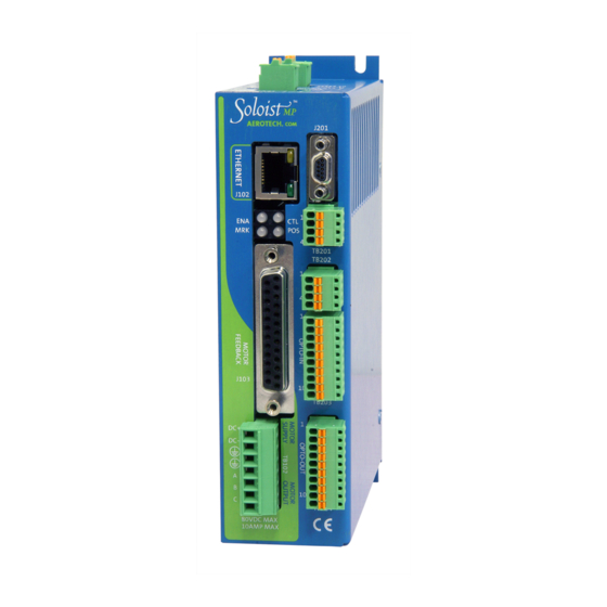
- Page 2 Soloist MP Hardware Manual Revision: 4.08.00 AEROTECH. AEROTECH. J201 J102 J102 TB201 TB202 J103 J103 TB203 TB204 80VDC MAX 80VDC MAX 10AMP MAX 10AMP MAX Artisan Technology Group - Quality Instrumentation ... Guaranteed | (888) 88-SOURCE | www.artisantg.com...
- Page 3 This manual contains proprietary information and may not be reproduced, disclosed, or used in whole or in part without the express written permission of Aerotech, Inc. Product names mentioned herein are used for identification purposes only and may be trademarks of their respective companies.
-
Page 4: Table Of Contents
Table of Contents Soloist MP Table of Contents Table of Contents List of Figures List of Tables EC Declaration of Conformity Agency Approvals Safety Procedures and Warnings Quick Installation Guide xiii Chapter 1: Introduction 1.1. Drive and Software Compatibility 1.2. Electrical Specifications 1.2.1. -
Page 5: Table Of Contents
Soloist MP Table of Contents 3.2.1. Solid State Relay Specifications (TB201) 3.3. Analog Output (TB202) 3.4. Analog Input (TB202) 3.5. Opto-Isolated Inputs (TB203) 3.6. Opto-Isolated Outputs (TB204) 3.7. Auxiliary Encoder Channel/PSO Output (J201) 3.7.1. Position Synchronized Output (PSO)/Laser Firing (J201) Chapter 4: Standard Interconnection Cables 4.1. -
Page 6: List Of Figures
ESTOP Sense Input (TB104) Figure 2-27: Typical Emergency Stop Circuit Figure 2-28: RS-232 Interface (TB105) Figure 3-1: Soloist MP with -IO Option Board Figure 3-2: Brake Connected to J103 Figure 3-3: Brake Connected to TB201 Figure 3-4: Analog Output 1 Connector (TB202) -
Page 7: Table Of Contents
Soloist MP Table of Contents This page intentionally left blank. www.aerotech.com Artisan Technology Group - Quality Instrumentation ... Guaranteed | (888) 88-SOURCE | www.artisantg.com... -
Page 8: List Of Tables
Table 2-7: Motor Power Output Connections (TB102) Table 2-8: Motor Power Output Mating Connector Table 2-9: Wire Colors for Aerotech Supplied Cables (Brushless) Table 2-10: Wire Colors for Aerotech Supplied Cables (DC Brush) Table 2-11: Wire Colors for Aerotech Supplied Cables (Stepper) - Page 9 Soloist MP Table of Contents Table 5-1: LED Description Table 5-2: Control Board Fuse Information Table 5-3: LED Description Table 5-4: Preventative Maintenance viii www.aerotech.com Artisan Technology Group - Quality Instrumentation ... Guaranteed | (888) 88-SOURCE | www.artisantg.com...
-
Page 10: Ec Declaration Of Conformity
Declaration of Conformity Soloist MP EC Declaration of Conformity Manufacturer Aerotech, Inc. Address 101 Zeta Drive Pittsburgh, PA 15238-2897 Product Soloist MP Model/Types This is to certify that the aforementioned product is in accordance with the applicable requirements of the... -
Page 11: Agency Approvals
Soloist MP Declaration of Conformity Agency Approvals Aerotech, Inc. Model Soloist MP Series Digital Drives have been tested and found to be in accordance to the following listed Agency Approvals: Approval / Certification: CUS NRTL Approving Agency: TUV SUD America Inc. -
Page 12: Safety Procedures And Warnings
8. Operator safeguarding requirements must be addressed during final integration of the product. D A N G E R : The Soloist MP case temperature may exceed 70°C in some applications. www.aerotech.com Artisan Technology Group - Quality Instrumentation ... Guaranteed | (888) 88-SOURCE | www.artisantg.com... - Page 13 Exceeding environmental or operating specifications can cause damage to the equipment. 5. If the Soloist MP is used in a manner not specified by the manufacturer, the protection provided by the Soloist MP can be impaired and result in damage, shock, injury, or death.
-
Page 14: Quick Installation Guide
Quick Installation Guide Soloist MP Quick Installation Guide This chapter describes the order in which connections and settings should typically be made to the Soloist MP. If a custom interconnection drawing was created for your system (look for a line item on your Sales Order under the heading “Integration”), that drawing can be found on your installation device. - Page 15 Soloist MP Quick Installation Guide This page intentionally left blank. www.aerotech.com Artisan Technology Group - Quality Instrumentation ... Guaranteed | (888) 88-SOURCE | www.artisantg.com...
-
Page 16: Chapter 1: Introduction
The Soloist MP is offered with an optional encoder interpolation feature (-MXU), an auxiliary square wave encoder input for dual loop control, dedicated analog and digital I/O (expandable with the -IO option), and separate power connections for motor and control supply voltages. -
Page 17: Table 1-1: Feature Summary
24 VDC, 2 A power supply for optional brake External Power Supply Options Refer to Section 2.1.3. for more information Cables Interconnection A complete list of Aerotech cables can be found on the website at http://www.aerotechmotioncontrol.com/manuals/index.aspx Joystick/Handwheel Refer to Section 4.1. Section 4.2. Chapter 1 www.aerotech.com... -
Page 18: Figure 1-2: Functional Diagram
Introduction Soloist MP The following block diagram shows a connection summary. For detailed connection information, refer to Chapter 2 and Chapter 3. -IO Option J201 Ethernet Port Encoder +5V / Common J102 Secondary PSO Output, Encoder Echo Encoder SIN, COS, MRK (RS422) -
Page 19: Drive And Software Compatibility
Soloist MP Introduction 1.1. Drive and Software Compatibility The following table lists the available Soloist drives and which version of the Soloist software first provided support for a given drive. Drives that list a specific version number in the Last Software Version column will not be supported after the listed version. -
Page 20: Electrical Specifications
Introduction Soloist MP 1.2. Electrical Specifications Table 1-4: Electrical Specifications MP 10 Motor Supply Input Voltage 10-80 VDC Maximum Continuous Input Current Input Current Refer to Section 1.2.1. System Power Requirements Control Input Voltage 24-80 VDC (±10%) Supply Input Current 1 A max... -
Page 21: System Power Requirements
Soloist MP Introduction 1.2.1. System Power Requirements The following equations can be used to determine total system power requirements. The actual power required from the mains supply will be the combination of actual motor power (work), motor resistance losses, and efficiency losses in the power electronics or power transformer. An EfficiencyFactor of approximately 90% should be used in the following equations. -
Page 22: Power Dissipation
If the result is lower than the known operating ambient temperature, additional measures are required to cool the Soloist MP. Mounting it to a large metal plate for extra heat-sinking and providing additional fan flow are suggested. -
Page 23: Mechanical Design
Soloist MP Introduction 1.3. Mechanical Design Install the unit into a construction compliant for unlimited circuits enclosure. Each unit should be separated from other drives and surrounded by 25 mm (1") of free air space. A space of 100 mm (4") should be allowed along the front of the unit for cable connections. -
Page 24: Environmental Specifications
Introduction Soloist MP 1.4. Environmental Specifications The environmental specifications for the Soloist MP are listed below. Ambient Temperature Operating: 0° to 50°C (32° to 122° F) Storage: -30° to 85°C (-22° to 185° F) Humidity Maximum relative humidity is 80% for temperatures up to 31°C. Decreasing linearly to 50% relative humidity at 40°C. - Page 25 Soloist MP Introduction This page intentionally left blank. Chapter 1 www.aerotech.com Artisan Technology Group - Quality Instrumentation ... Guaranteed | (888) 88-SOURCE | www.artisantg.com...
-
Page 26: Chapter 2: Installation And Configuration
D A N G E R : Hazardous Voltages are present on Soloist MP systems. D A N G E R : Soloist MP and PS-MP systems must be installed inside a rack or enclosure to restrict access while energized. -
Page 27: Control Supply Connections (Tb103)
The control power supply input allows the Soloist MP to maintain communications if the motor power is removed, such as in an Emergency Stop condition. The control power supply operates from 24-80 VDC (±10%). -
Page 28: Motor Supply Connections (Tb102)
A small ferrite filter may be required to minimize radiated emissions. This should be located close to the MP. Figure 2-2 for more details. W A R N I N G : Do not operate the Soloist MP without the safety ground connection in place. Core Ferrite ( EIZ00286, Ferroxcube #TX22/14/6.4-3C81 ) -
Page 29: External Power Supply Options
Soloist MP Installation and Configuration 2.1.3. External Power Supply Options Two VDC power options are available to power up to four MPs. Table 2-5: External Power Supply Options Description Power up to 4 drives, providing 300 watts of power (refer to Figure 2-3). -
Page 30: Figure 2-4: Ps-Mp Option
Installation and Configuration Soloist MP GRN/YEL #20 GRN/YEL #20 BLK #20 BLK/WHT #20 GRN/YEL #20 BLK #20 BLK/WHT #20 GRN/YEL #20 BLK #20 BLK/WHT #20 GRN/YEL #20 BLK #20 BLK/WHT #20 GRN/YEL TB103 CONTROL SUPPLY 24-80VDC 1AMP MAX Figure 2-4: PS-MP Option www.aerotech.com... -
Page 31: Minimizing Conducted, Radiated, And System Noise
The shield of the cables must be connected to the metal back shell in order for the product to conform to the radiated emission standards. The Soloist MP is a component designed to be integrated with other electronics. EMC testing must be conducted on the final product configuration. -
Page 32: Motor Output Connections
Installation and Configuration Soloist MP 2.2. Motor Output Connections The Soloist MP is capable of controlling three motor types: Brushless (see Section 2.2.1.) DC Brush (see Section 2.2.2.) Stepper (see Section 2.2.3.) For a complete list of electrical specifications, refer to Section 1.2. -
Page 33: Brushless Motor Connections
Both methods will identify the A, B, and C Hall/motor lead sets and indicate the correct connections to the drive. N O T E : If using standard Aerotech motors and cables, motor and encoder connection adjustments are not required. -
Page 34: Powered Motor Phasing
Installation and Configuration Soloist MP 2.2.1.1. Powered Motor Phasing To test the initial set of motor connections, run the MotorVerification.ab test program. The program will attempt to move the motor forward in a positive (CW) direction. Depending on the information that the program gathers during the test, you may be prompted to rearrange motor lead connections and run the test again. -
Page 35: Figure 2-6: Encoder And Hall Signal Diagnostics
Soloist MP Installation and Configuration Figure 2-6: Encoder and Hall Signal Diagnostics Chapter 2 www.aerotech.com Artisan Technology Group - Quality Instrumentation ... Guaranteed | (888) 88-SOURCE | www.artisantg.com... -
Page 36: Unpowered Motor And Feedback Phasing
1. Aerotech phasing configuration expects ØC to be the lead signal (in time), ØB to follow it, and ØA to follow ØB. This means that whichever signal has its sine wave peak farthest to the left should be designated as the ØC signal. -
Page 37: Figure 2-8: Hall Phasing With Oscilloscope
After the motor leads have been tested, the next step is to determine the phase of the Hall signals. The required (by an Aerotech system) relationship between motor and Hall leads is that the peak of a motor lead signal should correspond to the low voltage phase of the Hall signal (as shown in Figure 2-8). -
Page 38: Figure 2-9: Brushless Motor Phasing Goal
With the designations of the motor and Hall leads of a third party motor determined, the motor can now be connected to an Aerotech system. Connect motor lead A to motor connector A, motor lead B to motor connector B, and motor lead C to motor connector C. Connect Hall lead A to Pin 10 of the feedback connector. -
Page 39: Dc Brush Motor Connections
Red & Orange Yellow & Blue Black Yellow & Blue (1) Wire Color Set #1 is the typical Aerotech wire set used by Aerotech. (2) “&” (Red & Orange) indicates two wires; “ / ” (Green/White) indicates a single wire Chapter 2 www.aerotech.com... -
Page 40: Dc Brush Motor Phasing
When the voltmeter indicates a positive value, the motor leads have been identified. 5. Connect the motor lead from the voltmeter to the ØA motor terminal on the Soloist MP. Connect the motor lead from the negative lead of the voltmeter to the ØC motor terminal on the Soloist MP. -
Page 41: Stepper Motor Connections
Brown Yellow White White & Red (1) Wire Color Set #1 is the typical Aerotech wire set used by Aerotech. (2) “&” (Red & Orange) indicates two wires; “ / ” (Green/White) indicates a single wire Chapter 2 www.aerotech.com Artisan Technology Group - Quality Instrumentation ... Guaranteed | (888) 88-SOURCE | www.artisantg.com... -
Page 42: Stepper Motor Phasing
POSITIVE MOTION Figure 2-13: Clockwise Motor Rotation N O T E : If using standard Aerotech motors and cables, motor and encoder connection adjustments are not required. N O T E : After the motor has been phased, use the ReverseMotionDirection parameter to change the dir- ection of “positive”... -
Page 43: Motor Feedback Connections (J103)
Soloist MP Installation and Configuration 2.3. Motor Feedback Connections (J103) The motor feedback connector (a 25-pin, D-style connector) has inputs for an encoder, limit switches, Hall- effect devices, motor over-temperature device, 5 Volt encoder and limit power, and optional brake connection. -
Page 44: Encoder Interface (J103)
Soloist MP 2.3.1. Encoder Interface (J103) The Soloist MP is equipped with standard and auxiliary encoder feedback channels. The standard encoder interface is accessible through the Motor Feedback (J103) connector. The standard encoder interface will accept an RS-422 differential line driver signal. -
Page 45: Rs-422 Line Driver Encoder (Standard)
Soloist MP Installation and Configuration 2.3.1.1. RS-422 Line Driver Encoder (Standard) The standard encoder interface accepts an RS-422 differential quadrature line driver signal in the range of 0 to 5 Volts. It accepts a 10 MHz (max) encoder signal frequency (25 nsec minimum edge separation), producing 40 million counts per second after times four (x4) quadrature decoding. -
Page 46: Analog Encoder Interface
Installation and Configuration Soloist MP 2.3.1.2. Analog Encoder Interface If the -MXU option has been purchased, the standard encoder channel will accept an analog encoder input signal. The multiplication (interpolation) factor is determined by the EncoderMultiplicationFactor parameter. Table 2-14: Analog Encoder Specifications... -
Page 47: Figure 2-16: Analog Encoder Interface (J103)
Soloist MP Installation and Configuration MRK+ J103-7 82PF 82PF 82PF 82PF MRK- J103-6 AD822 82PF 82PF 10UF 6.3V SIN+ J103-17 82PF 82PF 82PF 82PF SIN- J103-18 AD822 82PF 82PF 10UF 6.3V COS+ J103-14 82PF 82PF 82PF 82PF COS- J103-15 AD822... -
Page 48: Encoder Phasing
Installation and Configuration Soloist MP 2.3.1.3. Encoder Phasing Incorrect encoder polarity will cause the system to fault when enabled or when a move command is issued. Figure 2-17 illustrates the proper encoder phasing for clockwise motor rotation (or positive forcer movement for linear motors). -
Page 49: Figure 2-18: Position Feedback In The Diagnostic Display
Soloist MP Installation and Configuration Figure 2-18: Position Feedback in the Diagnostic Display Chapter 2 www.aerotech.com Artisan Technology Group - Quality Instrumentation ... Guaranteed | (888) 88-SOURCE | www.artisantg.com... -
Page 50: Hall-Effect Interface (J103)
Installation and Configuration Soloist MP 2.3.2. Hall-Effect Interface (J103) The Hall-effect switch inputs are recommended for AC brushless motor commutation but not absolutely required. The Hall-effect inputs accept 5-24 VDC level signals. Refer to Section 2.2.1.1. for Hall-effect device phasing. -
Page 51: Thermistor Interface (J103)
Soloist MP Installation and Configuration 2.3.3. Thermistor Interface (J103) The thermistor input is used to detect an over temperature condition in a motor using a positive temperature coefficient sensor. As the temperature of the sensor increases, so does the resistance. Under normal operating conditions, the resistance of the thermistor is low (i.e., 100 ohms) which will result in a low input... -
Page 52: Encoder Fault Interface (J103)
Installation and Configuration Soloist MP 2.3.4. Encoder Fault Interface (J103) The encoder fault input is used with encoders having a fault output. Each manufacturer uses this signal to indicate different faults. Table 2-17: Encoder Fault Interface Pin Assignment (J103) Pin#... -
Page 53: End Of Travel Limit Input Interface (J103)
Soloist MP Installation and Configuration 2.3.5. End Of Travel Limit Input Interface (J103) End of Travel (EOT) limits are required to define the end of the physical travel on linear axes. Positive or clockwise motion is stopped by the clockwise (CW) end of travel limit input. Negative or counterclockwise motion is stopped by the counterclockwise (CCW) end of travel limit input. - Page 54 Installation and Configuration Soloist MP CW LMT J103-12 CCW LMT J103-24 HM LMT J103-22 Figure 2-23: End of Travel Limit Interface Input (J103) www.aerotech.com Chapter 2 Artisan Technology Group - Quality Instrumentation ... Guaranteed | (888) 88-SOURCE | www.artisantg.com...
-
Page 55: End Of Travel Limit Phasing
Soloist MP Installation and Configuration 2.3.5.1. End Of Travel Limit Phasing If the EOT limits are reversed, you will be able to move further into a limit but be unable to move out. To correct this, swap the connections to the CW and CCW inputs at the J103 connector. The logic level of the EOT limit inputs may be viewed in the diagnostic display (shown in... -
Page 56: Brake Output (J103)
Installation and Configuration Soloist MP 2.3.6. Brake Output (J103) The Brake Output pins provide a direct connection to the solid state relay on the optional -IO board. The brake output pins in J103 permit the brake to be wired with other signals in the feedback cable. The brake is configured for automatic or manual control using controller parameters (refer to the Soloist Help file for more... -
Page 57: Analog Input 0 (J103)
Soloist MP Installation and Configuration 2.3.7. Analog Input 0 (J103) Analog Input 0 is a 16-bit differential input that accepts a voltage in the range of ±10 volts with a resolution of 305 µVolts. Signals outside of this range may damage the input. To interface to a single-ended (non- differential) voltage source, connect the signal common of the source to the negative input (pin 8, ANALOG_ IN-) and the analog source signal to the positive input (pin 19, ANALOG_IN+). -
Page 58: Emergency Stop Sense Input (Tb104)
Installation and Configuration Soloist MP 2.4. Emergency Stop Sense Input (TB104) The ESTOP sense input (TB104) is used to monitor the state of an external safety circuit only. This state is indicated by the software and may be used to facilitate system restart. This ESTOP sense input is not intended to be a complete safety system. -
Page 59: Typical Estop Interface
Installation and Configuration 2.4.1. Typical ESTOP Interface The user can connect an external emergency stop relay circuit to the Soloist MP’s motor power supply input. This will remove power to the motor while maintaining control power, as shown in the Figure 2-27. -
Page 60: Rs-232 Interface (Tb105)
Installation and Configuration Soloist MP 2.5. RS-232 Interface (TB105) Connecting the RS-232 port to a user’s PC requires a standard cable (not a null modem). Table 2-25: RS-232 Connector Pin Assignment (TB105) Pin# Description In/Out/Bi RS-232 Transmit Output RS-232 Receive... -
Page 61: Pc Configuration And Operation Information
Soloist MP Installation and Configuration 2.6. PC Configuration and Operation Information For additional information about Soloist MP and PC configuration, hardware requirements, programming, utilities and system operation refer to the Soloist Help file. Chapter 2 www.aerotech.com Artisan Technology Group - Quality Instrumentation ... Guaranteed | (888) 88-SOURCE | www.artisantg.com... -
Page 62: Chapter 3: -I/O Expansion Board
The -IO option board is 8 digital opto-inputs, 8 digital opto-outputs, 1 analog input, 1 analog output, a second encoder channel, and a brake/relay output. D A N G E R : Always disconnect the Mains power connection before opening the Soloist MP chassis. -
Page 63: User Power (Tb201)
Soloist MP -IO Expansion Board 3.1. User Power (TB201) A user accessible power supply (+5V at 0.5 A) is available between the TB201 pin 3 +5V terminal and TB201 pin 4 GND terminal. Table 3-1: User Common Connector Pin Assignment (TB201) -
Page 64: Brake Power Supply (Tb201)
-IO Expansion Board Soloist MP 3.2. Brake Power Supply (TB201) TB201 is the power supply connection to the onboard solid state brake control relay. The relay is typically used to automatically control a fail-safe brake on a vertical axis. It can also be used as a general purpose output. -
Page 65: Figure 3-2: Brake Connected To J103
J103-25 BRAKE BRAKE - J103-13 NOISE SUPPRESSION CIRCUIT VARISTOR: AEROTECH P/N: ECR181 BRAKE PS- HARRIS P/N: V33ZA1 TB201-2 Figure 3-2: Brake Connected to J103 N O T E : The user is responsible for providing fuse protection for the brake circuit. -
Page 66: Figure 3-3: Brake Connected To Tb201
24VDC 1N5369 PS710A-1ASK BRAKE + J103-25 BRAKE BRAKE - J103-13 VARISTOR: AEROTECH P/N: ECR181 HARRIS P/N: V33ZA1 BRAKE PS- TB201-2 Figure 3-3: Brake Connected to TB201 www.aerotech.com Chapter 3 Artisan Technology Group - Quality Instrumentation ... Guaranteed | (888) 88-SOURCE | www.artisantg.com... -
Page 67: Solid State Relay Specifications (Tb201)
The user must verify that the brake power requirements are within the specifications of the Brake control relay listed below. Table 3-5: Relay Specifications Solid State Relay Rating (M36), Aerotech PN: ECS1074 Maximum Voltage 24 VDC Maximum Current 0.5 Amps... -
Page 68: Analog Output (Tb202)
-IO Expansion Board Soloist MP 3.3. Analog Output (TB202) The 16-bit analog output produces a single-ended output voltage in the range of ±5 V with a resolution of 153 µV. The maximum recommended output current is 5 mA. Analog outputs are referenced to TB202-1. The analog output is set to zero when the system is powered-up or during a system reset. -
Page 69: Analog Input (Tb202)
Soloist MP -IO Expansion Board 3.4. Analog Input (TB202) The I/O board analog input is a 12-bit differential input that accepts a voltage in the range of ±10 volts with a resolution of 4.88 millivolts. Signals outside of this range may damage the input. To interface to a single- ended (non-differential) voltage source, connect the signal common of the source to the negative input, and the analog source signal to the positive input. -
Page 70: Opto-Isolated Inputs (Tb203)
-IO Expansion Board Soloist MP 3.5. Opto-Isolated Inputs (TB203) These opto-isolated inputs use a PS2806-4 device and are configured for 5-24 volt input levels. The inputs may be connected to current sourcing or current sinking devices, as shown in Figure 3-7 Figure 3-8. -
Page 71: Figure 3-6: Opto-Isolated Inputs
Soloist MP -IO Expansion Board OPTOIN COM2 TB203-10 OPTOIN4 TB203-6 4.02K OPTOIN5 TB203-7 4.02K OPTOIN6 TB203-8 4.02K OPTOIN7 TB203-9 4.02K PS2806-4 OPTOIN COM1 TB203-1 OPTOIN0 TB203-2 4.02K OPTOIN1 TB203-3 4.02K OPTOIN2 TB203-4 4.02K OPTOIN3 TB203-5 4.02K PS2806-4 Figure 3-6: Opto-Isolated Inputs Chapter 3 www.aerotech.com... - Page 72 -IO Expansion Board Soloist MP TB203 INPUT SWITCHES OPTOIN0 TB203-2 OPTOIN1 TB203-3 5-24 VDC OPTOIN2 TB203-4 OPTOIN3 TB203-5 COMMON (0-3) TB203-1 Figure 3-7: Inputs Connected to a Current Sourcing Device TB203 COMMON (0-3) TB203-1 OPTOIN0 TB203-2 5-24 VDC OPTOIN1 TB203-3...
-
Page 73: Opto-Isolated Outputs (Tb204)
Soloist MP -IO Expansion Board 3.6. Opto-Isolated Outputs (TB204) The outputs are software configurable as sourcing or sinking. The outputs are driven by PS2802-4 opto- isolators rated for 24 volts maximum and up to 80 mA/output @ 20°C. Outputs must be connected in either all sinking or all sourcing mode. -
Page 74: Figure 3-9: Opto-Isolated Outputs (-Io Board)
-IO Expansion Board Soloist MP OPTOOUT V+ TB204-1 OPTOOUT3 TB204-6 OPTOOUT2 TB204-5 OPTOOUT1 TB204-4 OPTOOUT0 TB204-3 PS2802-4 OPTOOUT7 TB204-10 OPTOOUT6 TB204-9 OPTOOUT5 TB204-8 OPTOOUT4 TB204-7 PS2802-4 OPTOOUT V- TB204-2 PS2802-4 Figure 3-9: Opto-Isolated Outputs (-IO Board) www.aerotech.com Chapter 3 Artisan Technology Group - Quality Instrumentation ... Guaranteed | (888) 88-SOURCE | www.artisantg.com... -
Page 75: Table 3-15: Output Specifications (Tb204)
Soloist MP -IO Expansion Board Table 3-15: Output Specifications (TB204) PS2802-4 Opto Device Specifications Value Maximum Voltage 24 V maximum Maximum Sink/Source Current 80 mA/channel @ 20°C; 60 mA/channel @ 50°C Output Saturation Voltage 2.75 V at maximum current Output Resistance 33 Ω... - Page 76 -IO Expansion Board Soloist MP TB204 TB204-1 LOAD 5-24 VDC OUTPUT SWITCHES OPTOOUT0 TB204-3 LOAD OPTOOUT1 TB204-4 LOAD OPTOOUT2 TB204-5 LOAD OPTOOUT3 TB204-6 TB204-2 EACH OUTPUT 80 mA MAXIMUM DIODE REQUIRED ON EACH OUTPUT THAT DRIVES AN INDUCTIVE DEVICE (COIL), SUCH AS A RELAY.
-
Page 77: Auxiliary Encoder Channel/Pso Output (J201)
Soloist MP -IO Expansion Board 3.7. Auxiliary Encoder Channel/PSO Output (J201) The auxiliary encoder interface accepts a 5 VDC RS-422 differential quadrature line driver signal. It accepts a 10 MHz (max) encoder signal frequency (25 nsec minimum edge separation), producing 40 million counts per second, after times four (x4) quadrature decoding. -
Page 78: Figure 3-12: Auxiliary Encoder Channel (J201)
-IO Expansion Board Soloist MP AUX SIN- J201-9 AUX SIN+ ADG801 J201-4 ADM1485 ENCODER FAULT DETECTION AUX COS- J201-3 AUX COS+ ADG801 J201-2 ADM1485 AUX MRK- J201-1 AUX MRK+ ADG801 J201-6 ADM1485 Figure 3-12: Auxiliary Encoder Channel (J201) www.aerotech.com Chapter 3... -
Page 79: Position Synchronized Output (Pso)/Laser Firing (J201)
-IO Expansion Board 3.7.1. Position Synchronized Output (PSO)/Laser Firing (J201) The Soloist MP includes a Position Synchronized Output (PSO) feature. The PSO output is available on the dual function AUXMRK± differential signal lines (use of an RS-422 line receiver or opto-isolator is recommended). - Page 80 -IO Expansion Board Soloist MP Differential +5 VDC 120 - 180 (typical) J201 Active Low Aux. Marker Output * Opto-Isolated +5 VDC Isolated Section J201 10 mA 180 Aux. Marker To Laser Active Low 1N4148 Output* HCPL-2601 or 6N136 * Active low output shown. Opposite polarity available by reversing connections to Pins 1 and 6.
- Page 81 Soloist MP -IO Expansion Board This page intentionally left blank. Chapter 3 www.aerotech.com Artisan Technology Group - Quality Instrumentation ... Guaranteed | (888) 88-SOURCE | www.artisantg.com...
-
Page 82: Chapter 4: Standard Interconnection Cables
Accessories Soloist MP Chapter 4: Standard Interconnection Cables N O T E : A complete list of Aerotech cables can be found on the website at http://www.aerotechmotioncontrol.com/manuals/index.aspx. Table 4-1: Standard Interconnection Cables Cable Part # Description Joystick Section 4.1. ECZ01231 BBA32 Interconnect Cable (1) The “-xx”... -
Page 83: Joystick Interface
Accessories 4.1. Joystick Interface Aerotech joysticks JI (NEMA12 (IP54) rated) and JBV are powered from 5V and have a nominal 2.5V output in the center detent position. Three buttons are used to select axis pairs and speed ranges. An optional interlock signal is used to indicate to the controller that the joystick is present. -
Page 84: Table 4-2: Cable Part Numbers
Accessories Soloist MP DRIVE #2 AGND JOY-Y Analog Input 1+ Common Analog Input 1- Common Common +5 Volts Input Common Button A Input 1 Button B Input 0 Joy Interlock Input 2 DRIVE #1 AGND JOY-X Analog Input 1+ Common... -
Page 85: Handwheel Interface
Accessories 4.2. Handwheel Interface A handwheel (such as the Aerotech HW-xxx-xx) can be used to manually control axis position. The handwheel must provide 5V differential quadrature signals to the Soloist MP. A handwheel can be connected to the Aux I/O as shown in Figure 4-3. -
Page 86: Chapter 5: Maintenance
This section covers the internal boards, important board components, and how to clean the drive. Troubleshooting is covered in-depth in the Soloist Help file. D A N G E R : Always disconnect the Mains power connection before opening the Soloist MP chassis. -
Page 87: Control Board
Drawing Number: 690D1622 Rev. B Test Points Figure 5-1: Control Board Assembly D A N G E R : Always disconnect the Mains power connection before opening the Soloist MP chassis. Chapter 5 www.aerotech.com Artisan Technology Group - Quality Instrumentation ... Guaranteed | (888) 88-SOURCE | www.artisantg.com... - Page 88 Maintenance Soloist MP Table 5-2: Control Board Fuse Information Fuse Description Size Aerotech P/N Manufacturer's P/N Control Power at TB103-1 2 A S.B. EIF00136 LittelFuse 255002 Bus Power at TB102-1 5 A S.B. EIF00179 Wickman 1951500 (5 mm) Note: F1 is soldered to the circuit board.
-
Page 89: Preventative Maintenance
Cleaning The Soloist MP chassis can be wiped with a clean, dry, soft cloth. The cloth may be slightly moistened if required with water or isopropyl alcohol to aid in cleaning if necessary. In this case, be careful not to allow moisture to enter the Soloist MP or onto exposed connectors / components. -
Page 90: Appendix A: Warranty And Field Service
Aerotech makes no warranty that its products are fit for the use or purpose to which they may be put by the buyer, whether or not such use or purpose has been disclosed to Aerotech in specifications or drawings previously or subsequently provided, or whether or not Aerotech’s... - Page 91 Aerotech's approval. On-site Warranty Repair If an Aerotech product cannot be made functional by telephone assistance or by sending and having the customer install replacement parts, and cannot be returned to the Aerotech service center for repair, and if Aerotech determines the problem could be warranty-related, then the following policy applies:...
-
Page 92: Appendix B: Revision History
April 23, 2010 4.01.00 December 01, 2009 4.00.00 September 03, 2009 Revision changes have been archived. If you need a copy of this revision, contact Aerotech Global Technical Support. 2.02.00 September 18, 2008 2.01.00 August 19, 2008 2.00.00 September 04, 2007 1.01... - Page 93 Soloist MP Revision History This page intentionally left blank. Appendix B www.aerotech.com Artisan Technology Group - Quality Instrumentation ... Guaranteed | (888) 88-SOURCE | www.artisantg.com...
-
Page 94: Index
Index Soloist MP Index Brushless Motor Phasing Goal -I/O Expansion Board Check chassis for loose or damaged parts / hardware -IO Option Board Check for fluids or electrically conductive -IO Options material exposure -MXU Option 30-31 Cleaning Continuous Output Current specifications... - Page 95 Soloist MP Index Encoder Fault Interface Pin Assignment Installation and Configuration Encoder Interface (J207) Isolation Encoder Interface Pin Assignment Encoder Phasing 19,33 J103 19,28-30,32,35-39,41-42,49-51 Encoder Phasing Reference Diagram J201 End of Travel Limit Input Connections Joystick Interface End Of Travel Limit Input Interface (J207)
- Page 96 Index Soloist MP Output Specifications Screws Output Voltage specifications Din Rail Clip Outputs Connected in Current Sinking Mode Single Axis Joystick Interface Outputs Connected in Current Sourcing Mode solid state brake control relay Solid State Relay Rating PC Configuration and Operation Information...
- Page 97 Soloist MP Index User Power Supply specifications verifying motor connections Wire Colors for Supplied Cables 18,24,26 Wiring Control Supply www.aerotech.com Artisan Technology Group - Quality Instrumentation ... Guaranteed | (888) 88-SOURCE | www.artisantg.com...
- Page 98 Artisan Technology Group is your source for quality new and certified-used/pre-owned equipment SERVICE CENTER REPAIRS WE BUY USED EQUIPMENT • FAST SHIPPING AND DELIVERY Experienced engineers and technicians on staff Sell your excess, underutilized, and idle used equipment at our full-service, in-house repair center We also offer credit for buy-backs and trade-ins •...
Need help?
Do you have a question about the Soloist MP and is the answer not in the manual?
Questions and answers