Table of Contents

Related Manuals for Aerotech Ensemble QLAB


Summary of Contents for Aerotech Ensemble QLAB
- Page 1 Ensemble QLAB Hardware Manual P/N: EDU224 (Revision 1.00.00) Dedicated to the Science of Motion Aerotech, Inc. 101 Zeta Drive, Pittsburgh, PA 15238-2897 Phone: +1-412-963-7470 Fax: +1-412-963-7459 www.aerotech.com...
-
Page 2: Technical Support
Email: sales@aerotech.co.uk Email: service@aerotech.tw N O T E : Aerotech continually improves its product offerings; listed options may be superseded at any time. Refer to the most recent edition of the Aerotech Motion Control Product Guide for the most current product information at www.aerotech.com. -
Page 3: Table Of Contents
Ensemble QLAB Hardware Manual Table of Contents Table of Contents Table of Contents List of Figures List of Tables EC Declaration of Conformity Safety Procedures and Warnings Quick Installation Guide Chapter 1: Introduction 1.1. Electrical Specifications 1.2. Mechanical Specifications 1.3. Environmental Specifications 1.4. -
Page 4: List Of Figures
Table of Contents Ensemble QLAB Hardware Manual List of Figures Figure 1-1: Ensemble QLAB Controller Figure 1-2: Functional Diagram Figure 1-3: Dimensions Figure 2-1: Power and Control Connections Figure 2-2: Power Switch Figure 2-3: ESTOP Sense Input (TB102) Figure 2-4: PSO Interface... -
Page 5: List Of Tables
Ensemble QLAB Hardware Manual Table of Contents List of Tables Table 1-1: Ordering Options Table 1-2: Electrical Specifications Table 1-3: Physical Specifications Table 1-4: Ensemble Drive and Software Compatibility Table 2-1: Main AC Power Input Voltages and Current Requirements Table 2-2:... - Page 6 Table of Contents Ensemble QLAB Hardware Manual www.aerotech.com...
-
Page 7: Ec Declaration Of Conformity
Ensemble QLAB Hardware Manual Declaration of Conformity EC Declaration of Conformity Manufacturer Aerotech, Inc. Address 101 Zeta Drive Pittsburgh, PA 15238-2897 Product Ensemble QLAB Model/Types This is to certify that the aforementioned product is in accordance with the applicable requirements of the... - Page 8 Declaration of Conformity Ensemble QLAB Hardware Manual viii www.aerotech.com...
-
Page 9: Safety Procedures And Warnings
2. All service and maintenance must be performed by qualified personnel. 3. If the Ensemble QLAB is used in a manner not specified by the manufacturer, any protection provided by the Ensemble QLAB can be impaired and result in damage, shock, injury, or death. - Page 10 Safety Procedures and Warnings Ensemble QLAB Hardware Manual www.aerotech.com...
-
Page 11: Quick Installation Guide
This chapter describes the order in which connections and settings should typically be made to the Ensemble QLAB. If a custom interconnection drawing was created for your system (look for a line item on your Sales Order under the heading “Integration”), that drawing can be found on your software or documentation disc. - Page 12 Quick Installation Guide Ensemble QLAB Hardware Manual www.aerotech.com...
-
Page 13: Chapter 1: Introduction
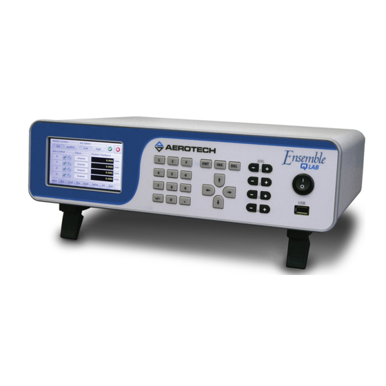
Introduction Chapter 1: Introduction Aerotech’s Ensemble QLAB is a one to four axis desktop standalone motion controller with an integrated power supply. The Ensemble QLAB is designed for applications where ease of operation is desired without sacrificing overall system capability. For simple operations the front-panel interface allows an operator to quickly execute simple operations such as jogging, homing, and moving to fixed positions. -
Page 14: Table 1-1: Ordering Options
Introduction Ensemble QLAB Hardware Manual Table 1-1: Ordering Options Number of Axes (required) -2AX Configured for 2 axis motor operation -3AX Configured for 3 axis motor operation -4AX Configured for 4 axis motor operation Line Voltage (required) 115 VAC input... -
Page 15: Figure 1-2: Functional Diagram
Ensemble QLAB Hardware Manual Introduction The following block diagram shows a connection summary (refer to Chapter 2 for more detailed connection information). Controller Amplifier Keypad PSO Output LCD Touch Output Common Display 4 Opto Outputs AUX I/O 4 Opto Inputs... -
Page 16: Electrical Specifications
Introduction Ensemble QLAB Hardware Manual 1.1. Electrical Specifications The electrical specifications for the Ensemble QLAB are listed below. Table 1-2: Electrical Specifications Description Ensemble QLAB Power Input Voltage 100 VAC 115 VAC 200 VAC 230 VAC Supply Input Frequency 50-60 Hz... -
Page 17: Mechanical Specifications
Ensemble QLAB Hardware Manual Introduction 1.2. Mechanical Specifications The following figure shows the Ensemble QLAB package dimensions. ETHERNET AUX I/O JOYSTICK ESTOP AXIS J106 J105 TB101 J104 J103 95.6 [3.76] 13.3 [0.52] 44.8 [1.76] 370.2 [14.58] 32.9 [1.29] 304.4 [11.99]... -
Page 18: Environmental Specifications
Introduction Ensemble QLAB Hardware Manual 1.3. Environmental Specifications The environmental specifications for the Ensemble QLAB are listed below. Ambient Temperature Operating: 0° to 50°C (32° to 122° F) Storage: -30° to 85°C (-22° to 185° F) Humidity Maximum relative humidity is 80% for temperatures up to 31°C. -
Page 19: Drive And Software Compatibility
Ensemble QLAB Hardware Manual Introduction 1.4. Drive and Software Compatibility The following table lists the available Ensemble drives and which version of the Ensemble software first provided support for a given drive. Drives that list a specific version number in the Last Version column will not be supported after the listed version. - Page 20 Introduction Ensemble QLAB Hardware Manual Chapter 1 www.aerotech.com...
-
Page 21: Chapter 2: Installation And Configuration
System part number The Ensemble QLAB power label contains the factory configured AC power requirements. D A N G E R : The AC power label should be changed if the Ensemble QLAB chassis is reconfigured for a different AC input voltage. -
Page 22: Electrical Installation
Installation and Configuration Ensemble QLAB Hardware Manual 2.2. Electrical Installation Motor, power, control, and position feedback cable connections are made to the rear of the Ensemble QLAB. For a complete list of electrical specifications, refer to Section 1.1. Electrical Specifications. -
Page 23: Ac Power Connection
2.2.1. AC Power Connection AC input power to the Ensemble QLAB is applied to the AC power receptacle that is located on the rear panel. The power cord connected to this receptacle also provides the protective earth ground connection and may serve as a Mains disconnect. -
Page 24: Minimizing Conducted, Radiated, And System Noise
7. Ferrite beads or Aerotech’s FBF-1 or FBF-2 filter adapters, may be used on the motor leads to reduce the effects of amplifier EMI/RFI, produced by PWM (pulse width modulation) amplifiers. Refer to the FBF-1 and FBF-2 drawings on your software disc for more information on the ferrite beads. -
Page 25: Motor And Feedback Connections
Ensemble QLAB Hardware Manual Installation and Configuration 2.3. Motor and Feedback Connections Table 2-3: Motor Power and Feedback Connector Description Connector Shield connection Common ground Common ground Stage ID Common ground Common ground Common ground Common ground Common ground Signal shield connection... -
Page 26: Emergency Stop Sense Input (Tb101)
Installation and Configuration Ensemble QLAB Hardware Manual 2.4. Emergency Stop Sense Input (TB101) The ESTOP sense input is used to monitor the state of an external safety circuit only. This state is indicated by the software and may be used to facilitate system restart. This ESTOP sense input is not intended to be a complete safety system. -
Page 27: Auxiliary I/O Connector (J106)
Ensemble QLAB Hardware Manual Installation and Configuration 2.5. Auxiliary I/O Connector (J106) The Auxiliary I/O connector provides 6 digital inputs, 1 analog and 4 digital outputs, and PSO outputs. Table 2-6: Auxiliary I/O Interface Pin Assignment (J106) Pin# Description In/Out/Bi Connector... -
Page 28: Position Synchronized Output (Pso)
Ensemble QLAB Hardware Manual 2.5.1. Position Synchronized Output (PSO) The Ensemble QLAB includes a Position Synchronized Output (PSO) feature. The PSO output is available on the dual function Laser Output 1 signal lines (optically-isolated open drain/open source format or as RS- 422 differential signals). -
Page 29: Figure 2-4: Pso Interface
Ensemble QLAB Hardware Manual Installation and Configuration Single Ended +5 VDC J106 Active Low Output Aux. Marker Active High Output 74AHCT1G125 Differential +5 VDC 120 - 180 Ω (typical) J106 Active Low Aux. Marker Output * Opto-Isolated +5 VDC Isolated Section J106 10 mA 180 Ω... -
Page 30: Opto-Isolated Outputs
Installation and Configuration Ensemble QLAB Hardware Manual 2.5.2. Opto-Isolated Outputs 0-3 All outputs are rated for 24 VDC and 80 mA per output and can be connected as current sinking (Figure 2-5) or current sourcing (Figure 2-6). Table 2-9: Port 0 Digital Output Connector Pin Assignment... -
Page 31: Figure 2-6: Outputs Connected In Current Sourcing Mode (J106)
Ensemble QLAB Hardware Manual Installation and Configuration J106 OPTOCOM J106-15 OPTOOUT0 J106-7 LOAD OPTOOUT1 J106-8 LOAD OPTOOUT2 J106-9 5-24 VDC LOAD OPTOOUT3 J106-16 OUTPUT SWITCHES LOAD EACH OUTPUT 80 mA MAXIMUM DIODE REQUIRED ON EACH OUTPUT THAT DRIVES AN INDUCTIVE DEVICE (COIL), SUCH AS A RELAY. -
Page 32: Opto-Isolated Inputs
Installation and Configuration Ensemble QLAB Hardware Manual 2.5.3. Opto-Isolated Inputs 0-3 User inputs 0-3 are scaled for an input voltage of 5-24 VDC. Figure 2-7 Figure 2-8, respectively, illustrate how to connect a device in current sinking and sourcing current modes. -
Page 33: Figure 2-8: Inputs Connected In Current Sourcing Mode (J106)
Ensemble QLAB Hardware Manual Installation and Configuration J106 INPUT SWITCHES OPTOIN0 J106-17 OPTOIN1 J106-18 OPTOIN2 J106-25 5-24VDC OPTOIN3 J106-26 OPTOINCOM J106-24 Figure 2-8: Inputs Connected in Current Sourcing Mode (J106) www.aerotech.com Chapter 2... -
Page 34: High-Speed User Inputs
Installation and Configuration Ensemble QLAB Hardware Manual 2.5.4. High-Speed User Inputs 4-5 The high-speed inputs are scaled for an input voltage of 5- 24 VDC. The high-speed inputs are isolated by an HCPL-0630 and have a typical delay of 50 ns. -
Page 35: Analog Output
Ensemble QLAB Hardware Manual Installation and Configuration 2.5.5. Analog Output 4 Analog Output 4 produces a single-ended output in the range of ±10 volts with a resolution of 305 μV (16-bit). The maximum recommended output current is 5 mA (2 k Ohm load). The analog output voltage is referenced to J106-23. -
Page 36: Joystick Interface (J105)
2.6. Joystick Interface (J105) Aerotech joysticks JI (NEMA12 (IP54) rated) and JBV are powered from 5V and have a nominal 2.5V output in the center detent position. Two switches are used to select axis pairs and speed ranges. An optional interlock signal is used to indicate to the controller that the joystick is present. -
Page 37: Table 2-15: Joystick Connector Pin Assignment (J105)
Ensemble QLAB Hardware Manual Installation and Configuration Table 2-15: Joystick Connector Pin Assignment (J105) Description In/Out/Bi Connector +5 Volt Power to joystick Output Button A (Axis Select) Input Analog Input 1 [Joystick X] Input Analog Common Analog Input 0 Input... -
Page 38: Analog Outputs (0-3) (J105)
Installation and Configuration Ensemble QLAB Hardware Manual 2.6.1. Analog Outputs (0-3) (J105) Analog Outputs 0-3 produce a single-ended output in the range of ±10 V with a resolution of 305 μV (16-bit). The maximum recommended output current is 5 mA (2 k Ohm load). The analog output voltage is referenced to an Analog Common pin. -
Page 39: Analog Inputs (0-3) (J105)
Ensemble QLAB Hardware Manual Installation and Configuration 2.6.2. Analog Inputs (0-3) (J105) Analog Inputs 0-3 are 16-bit single-ended (non-differential) inputs that accept a voltage in the range of +-10V with a resolution of 305uV. Signals outside of this range may damage the input. To read a signal from channel 0, connect the signal common of the source to analog common (pin 8, Analog Common) and the analog source signal to analog input 0 (pin 5, Analog Input 0). -
Page 40: Communication (Ethernet And Usb)
Method 1: Directly connect to the PC with a standard USB cable. The cable connector type must be Type A or Type B male depending on the PC, and Type B male on the Ensemble QLAB. Method 2: Connect through a USB hub. The cable connector type must be Type A or Type B male depending on the hub, and Type B male on the Ensemble QLAB. -
Page 41: Ethernet Interface
Aerotech recommends Method 2. Method 2 is a more typical configuration. The network can be a local network (the PC and Ensemble QLAB are connected through a hub or switch) or remote (the devices are connected through a router). When connecting to a remote network, a crossover cable cannot be used;... -
Page 42: Pc Configuration And Operation Information
Installation and Configuration Ensemble QLAB Hardware Manual 2.8. PC Configuration and Operation Information For additional information about Ensemble QLAB and PC configuration, hardware requirements, programming, utilities and system operation refer to the Ensemble Help file. Chapter 2 www.aerotech.com... -
Page 43: Chapter 3: Maintenance
The electrical power must be disconnected from the Ensemble QLAB while cleaning. Do not allow cleaning substances or other fluids to enter the Ensemble QLAB or to get on to any of the connectors. Avoid cleaning labels to prevent removing the label information. - Page 44 Maintenance Ensemble QLAB Hardware Manual Chapter 3 www.aerotech.com...
-
Page 45: Appendix A: Warranty And Field Service
Aerotech makes no warranty that its products are fit for the use or purpose to which they may be put by the buyer, where or not such use or purpose has been... - Page 46 Repair sending and having the customer install replacement parts, and cannot be returned to the Aerotech service center for repair, and if Aerotech determines the problem could be warranty-related, then the following policy applies: Aerotech will provide an on-site field service representative in a reasonable amount of time, provided that the customer issues a valid purchase order to Aerotech covering all transportation and subsistence costs.
-
Page 47: Appendix B: Revision History
Ensemble QLAB Hardware Manual Revision History Appendix B: Revision History Rev # Date Description 1.00.00 November 8, 2013 New Manual www.aerotech.com Appendix B... - Page 48 Revision History Ensemble QLAB Hardware Manual Appendix B www.aerotech.com...
-
Page 49: Index
Ensemble QLAB Hardware Manual Index Index Feedback Connections Ferrite Bead Part Numbers 2006/95/EC Functional Diagram fuse AC Power Connection Altitude High-Speed User Inputs 4-5 Ambient Temperature Humidity Analog Input 0 Analog Output 4 inspect Auxiliary I/O Connector (J106) inspect all cables and connections... - Page 50 Index Ensemble QLAB Hardware Manual Overview PC Configuration and Operation Information Peak Output Current Pollution Position Synchronized Output Power Amplifier Bandwidth Power Supply Preventative Maintenance PS2815-4 Opto-Device Specifications PS7214-1A Opto Device Specifications Quick Installation Guide Safety Procedures and Warnings Sensor Resolution...
Need help?
Do you have a question about the Ensemble QLAB and is the answer not in the manual?
Questions and answers