Table of Contents
Advertisement
Quick Links
Advertisement
Table of Contents

Related Manuals for Aerotech MPG


Summary of Contents for Aerotech MPG
-
Page 1: Mpg Handwheel Pendant
MPG Handwheel Pendant HARDWARE MANUAL Revision 2.00... - Page 2 This manual contains proprietary information and may not be reproduced, disclosed, or used in whole or in part without the express written permission of Aerotech, Inc. Product names mentioned herein are used for identification purposes only and may be trademarks of their respective companies.
-
Page 3: Table Of Contents
2.1.6. Connect the MPG to the Nservo 2.1.7. Connect the MPG to the Npaq 2.1.8. Connect the MPG to the Epaq 2.1.9. Connect the MPG to the Epaq MR/Npaq MR 2.2. A3200 Configuration Information 2.2.1. Software Version 3.00.000 and Above 2.2.2. - Page 4 Table of Contents MPG Hardware Manual This page intentionally left blank. www.aerotech.com...
-
Page 5: List Of Figures
Figure 2-18: Assigning Axis Names Figure 2-19: Defining Incremental Distance Figure 2-20: Defining the MPG Handwheel Connection (Npaq example shown) Figure 2-21: Defining the MPG I/O Connection (Npaq example shown) Figure 2-22: Define Multiplier Switch Inputs (4.05.000 and MP/ML only) - Page 6 List of Figures MPG Hardware Manual Figure 2-48: Defining the MPG Handwheel Connection Figure 2-49: Defining the MPG I/O Connection Figure 2-50: Save Program Changes Figure 2-51: Copying Files to the Controller Figure 2-52: Opening the Configuration Manager Figure 2-53:...
-
Page 7: List Of Tables
MPG Hardware Manual List of Tables List of Tables Table 1-1: Electrical Specifications Table 2-1: XR3 Adapter Cable Connector Pinout Table 2-2: XC4/XC4e Adapter Cable Connector Pinout Table 2-3: HPe/HLe Adapter Cable Connector Pinout Table 2-4: CP/CL Adapter Cable Connector Pinout... - Page 8 List of Tables MPG Hardware Manual This page intentionally left blank. www.aerotech.com...
-
Page 9: Eu Declaration Of Conformity
MPG Hardware Manual EU Declaration of Conformity EU Declaration of Conformity Manufacturer Aerotech, Inc. Address 101 Zeta Drive Pittsburgh, PA 15238-2811 Product Model/Types This is to certify that the aforementioned product is in accordance with the applicable requirements of the following Directive(s):... - Page 10 EU Declaration of Conformity MPG Hardware Manual This page intentionally left blank. www.aerotech.com...
-
Page 11: Safety Procedures And Warnings
IMPORTANT: This manual tells you how to carefully and correctly use and operate the MPG. Read all parts of this manual before you install or operate the MPG or before you do maintenance to your system. To prevent injury to you and damage to the equipment, obey the precautions in this manual. - Page 12 Safety Procedures and Warnings MPG Hardware Manual This page intentionally left blank. www.aerotech.com...
-
Page 13: Chapter 1: Introduction
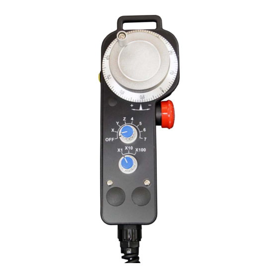
MPG Hardware Manual Chapter 1: Introduction Chapter 1: Introduction The MPG (Manual Pulse Generator) input device for the A3200 and Ensemble provides the capability to manually fine-position up to six axes. Six axis selector switch (Axis Select) Three position distance multiplier... -
Page 14: Mechanical Design
1.1. Mechanical Design MPG Hardware Manual 1.1. Mechanical Design IMPORTANT: All specifications and illustrations are for reference only and were complete and accurate as of the release of this manual. To find the newest information about this product, refer to www.aerotech.com. -
Page 15: Environmental Specifications
MPG Hardware Manual 1.2. Environmental Specifications 1.2. Environmental Specifications The environmental specifications for the MPG are listed below. Operating: 5° to 40°C (41° to 104° F) Ambient Temperature Storage: -20° to 70°C (-4° to 158° F) Maximum relative humidity is 80% for temperatures up to 31°C. - Page 16 1.2. Environmental Specifications MPG Hardware Manual This page intentionally left blank. www.aerotech.com...
-
Page 17: Chapter 2: Installation And Configuration
Each MPG adapter cable is labeled to identify the receiving connector on the drive. IMPORTANT: The 7th axis position of the axis select switch is not supported. DC Power Connections The MPG requires 24 VDC at 500 mA. Power can be supplied through the BRAKE24-2 option (Figure 2-1) or a user-provided power supply. - Page 18 MPG Hardware Manual Emergency Stop Connections The emergency stop (ESTOP) switch on the MPG can be connected in series with the user-supplied ESTOP and Safe Torque Off (STO) circuit. There are two normally-closed switch contacts: ESTOP NC1 and ESTOP NC2. Refer to drive hardware manual for ESTOP switch connection information. Refer to the drive sub-sections for specific wire colors.
-
Page 19: Connect The Mpg To The Automation1 Xr3
MPG Hardware Manual 2.1.1. Connect the MPG to the Automation1 XR3 2.1.1. Connect the MPG to the Automation1 XR3 Connect to the Aux Encoder, DIN , and STO connectors and use digital input bits 0 through 8. The handwheel uses the second auxiliary encoder input channel. - Page 20 2.1.1. Connect the MPG to the Automation1 XR3 MPG Hardware Manual Figure 2-4: MPG to XR3 Cable Drawing www.aerotech.com...
- Page 21 MPG Hardware Manual 2.1.1. Connect the MPG to the Automation1 XR3 The adapter cable that is supplied by Aerotech has wires (ESTOP NC1 and ESTOP NC2) that can be connected to a user-supplied safety device. To bypass the user-supplied safety device, connect the ESTOP NC1- and ESTOP NC2-labeled wires directly to the 24 V.
-
Page 22: Connect The Mpg To The Automation1 Xc4/Xc4E
2.1.2. Connect the MPG to the Automation1 XC4/XC4e MPG Hardware Manual 2.1.2. Connect the MPG to the Automation1 XC4/XC4e The XC4 or XC4e must be equipped with the -IO option. Connect to the AUX I/O and DIGITAL IN 1 connectors and use digital input bits 0 through 8. The handwheel uses the auxiliary encoder input channel. - Page 23 MPG Hardware Manual 2.1.2. Connect the MPG to the Automation1 XC4/XC4e Figure 2-6: MPG to XC4/XC4e Cable Drawing www.aerotech.com...
- Page 24 2.1.2. Connect the MPG to the Automation1 XC4/XC4e MPG Hardware Manual The adapter cable that is supplied by Aerotech has wires (ESTOP NC1 and ESTOP NC2) that can be connected to a user-supplied safety device. To bypass the user-supplied safety device, connect the ESTOP NC1 and ESTOP NC2 labeled wires directly to the 24 V.
-
Page 25: Connect The Mpg To The Hpe/Hle
MPG Hardware Manual 2.1.3. Connect the MPG to the HPe/HLe 2.1.3. Connect the MPG to the HPe/HLe The HPe or HLe must be equipped with the -IO option. Connect to the J205 (Auxiliary I/O) and TB305 (I/O) connectors and use digital input bits 0 through 8. The handwheel uses the auxiliary encoder input channel. - Page 26 2.1.3. Connect the MPG to the HPe/HLe MPG Hardware Manual Figure 2-8: MPG to HPe/HLe Cable Drawing www.aerotech.com...
-
Page 27: Connect The Mpg To The Cp/Cl
MPG Hardware Manual 2.1.4. Connect the MPG to the CP/CL 2.1.4. Connect the MPG to the CP/CL The CP or CL must be equipped with the -IO option. Connect to the Auxiliary I/O (CP: J104; CL: J105) and TB204 (I/O) connectors and use digital input bits 0 through 8. The handwheel uses the auxiliary encoder input channel. - Page 28 2.1.4. Connect the MPG to the CP/CL MPG Hardware Manual Figure 2-9: MPG to CP/CL Cable Drawing www.aerotech.com...
-
Page 29: Connect The Mpg To The Mp/Ml
MPG Hardware Manual 2.1.5. Connect the MPG to the MP/ML 2.1.5. Connect the MPG to the MP/ML The MP or ML must be equipped with the -IO option. Connect to the J201 (Auxiliary I/O) and TB203 (I/O) connectors and use digital input bits 0 through 7. The handwheel uses the auxiliary encoder input channel. - Page 30 2.1.5. Connect the MPG to the MP/ML MPG Hardware Manual Figure 2-10: MPG to MP/ML Cable Drawing www.aerotech.com...
-
Page 31: Connect The Mpg To The Nservo
MPG Hardware Manual 2.1.6. Connect the MPG to the Nservo 2.1.6. Connect the MPG to the Nservo Connect to the J107 (Auxiliary Encoder), J108 (Digital Outputs), J109 (Digital Inputs) and J110 (PSO/Brake) connectors and use digital input bits 0 through 7 and 12. The handwheel uses the auxiliary encoder input channel on J107. - Page 32 2.1.6. Connect the MPG to the Nservo MPG Hardware Manual Figure 2-11: MPG to Nservo Cable Drawing www.aerotech.com...
-
Page 33: Connect The Mpg To The Npaq
MPG Hardware Manual 2.1.7. Connect the MPG to the Npaq 2.1.7. Connect the MPG to the Npaq Connect to the J8 (High Speed I/O), J9 (I/O) and J12 (Misc. I/O) connectors and use digital input bits 0 through 7 and 12. The handwheel uses the second auxiliary encoder input channel. - Page 34 2.1.7. Connect the MPG to the Npaq MPG Hardware Manual Figure 2-12: MPG to Npaq Cable Drawing www.aerotech.com...
-
Page 35: Connect The Mpg To The Epaq
MPG Hardware Manual 2.1.8. Connect the MPG to the Epaq 2.1.8. Connect the MPG to the Epaq Connect to the Opto-In, and the Auxiliary Encoder connectors and use digital input bits 0 through 7. The handwheel uses an auxiliary encoder input channel. - Page 36 2.1.8. Connect the MPG to the Epaq MPG Hardware Manual Figure 2-13: MPG to Epaq Cable Drawing www.aerotech.com...
-
Page 37: Connect The Mpg To The Epaq Mr/Npaq Mr
MPG Hardware Manual 2.1.9. Connect the MPG to the Epaq MR/Npaq MR 2.1.9. Connect the MPG to the Epaq MR/Npaq MR Connect to the Digital/Analog I/O, and the Auxiliary Encoder connectors and use digital input bits 0 through 7. The handwheel uses an auxiliary encoder input channel. - Page 38 2.1.9. Connect the MPG to the Epaq MR/Npaq MR MPG Hardware Manual Figure 2-14: MPG to Epaq MR/Npaq MR Cable Drawing www.aerotech.com...
-
Page 39: A3200 Configuration Information
3.00.000. The MPG requires an AeroBasic program running on a secondary task to monitor the MPG switches and command the axes to move when the user rotates the manual pulse generator (MPG or handwheel). - Page 40 MPGSingleAxisInclude.pgm file. MPGMultipleAxisInclude.pgm and MPGSingleAxisInclude.pgm define the parameters by which the MPG operates. The MPGInclude.pgm file sets global variables to allow the system to recognize the MPG. The MPGSample.pgm shows a sample of how the MPG can be used. Figure 2-16: MPG Program Options The following steps will show how to configure the MPG.pgm, select the single or multiple axis include...
- Page 41 MPG Hardware Manual 2.2.1. Software Version 3.00.000 and Above Open the MPG.Pgm and the appropriate include file. If you have the MPG connected to an Npaq or Nservo then you should open the MPGMultipleAxisInclude.pgm. If you have the MPG connected to an HLe, HPe, CP, CL, MP, or ML then open the MPGSingleAxisInclude.pgm.
- Page 42 2.2.1. Software Version 3.00.000 and Above MPG Hardware Manual Step 1: Modify the first six lines of the program beginning with “#define”, changing the second column of axis names to match the names of the axes in your system. Figure 2-18: Assigning Axis Names www.aerotech.com...
- Page 43 Define the distance (metric) of an axis move equal to one tick of the handwheel. WARNING: If this distance is too large, Position Errors or other faults will occur as the axis motion is commanded by the MPG. Figure 2-19: Defining Incremental Distance www.aerotech.com...
- Page 44 Define the name of the axis that the MPG handwheel is connected to. IMPORTANT: If connecting an MPG to an Npaq, the A3200 controller will expect the encoder channel of the MPG to be connected to the second auxiliary encoder channel of the Npaq (typically designated as the Y axis).
- Page 45 Define the name of the axis that the MPG I/O is connected to. IMPORTANT: If connecting an MPG to an Npaq, the A3200 controller will expect the I/O of the MPG to be connected to the first axis of the Npaq (typically designated as the X axis). Figure 2-21: Defining the MPG I/O Connection (Npaq example shown) www.aerotech.com...
- Page 46 MPG Hardware Manual Step 5: IMPORTANT: This step is only for users running software version 4.05.000 and have the MPG connected to an Ndrive MP or Ndrive ML. Define the inputs for the three multiplier switches in the MPGSingleAxisInclude.pgm. Figure 2-22: Define Multiplier Switch Inputs (4.05.000 and MP/ML only)
- Page 47 MPG Hardware Manual 2.2.1. Software Version 3.00.000 and Above Step 6: Save any changes made to each file by selecting the file and clicking the save button on the toolbar. The Save All option (located in the File menu) can also be used. After saving, these files can be closed.
- Page 48 2.2.1. Software Version 3.00.000 and Above MPG Hardware Manual Step 7: Open the Program Automation folder under the controller node in the Network Explorer. The Network Explorer can be pinned to the page to see the changes being made to Program Automation. Right click on the Program Automation folder and select Add…...
- Page 49 MPG.pgm file. Set the Mode to RunSilent and set the Task to “Task 2”. This will start the MPG.pgm program running in Task 2 after initializing the A3200. Click OK when complete.
- Page 50 The code within MPGSample.pgm can be used as an example of how to interface with the MPG from your own program. If you switch to Task 2, notice that the MPG program is already running in that task. Figure 2-27: Opening the Sample Program (MPGSample.pgm)
-
Page 51: Software Version 2.55 Or Lower
3.00.000 or higher. The MPG requires a CNC G-Code program running on a secondary task to monitor the MPG switches and command the axes to move when the user rotates the manual pulse generator (MPG or handwheel). - Page 52 There are six sub-folders within the MPG folder. Four sub-folders contain variations of the MPG.Pgm program required for the four models of the MPG. The MPG.Pgm defines the parameters by which the handwheel operates. The Include sub-folder contains MPG_INCLUDE.Pgm. The MPG_INCLUDE.Pgm sets global variables to allow the system to recognize the MPG.
- Page 53 2.2.2. Software Version 2.55 or Lower Step 1: Open the MPG.Pgm for the model of your MPG (Npaq, Nservo, HPe, HLe, or CP/CL), from the appropriate sub-folder. Modify the first six lines of the program beginning with “#define”, changing the second column of axis names to match the names of the axes in your system.
- Page 54 Define the distance (metric) of an axis move equal to one tick of the handwheel. WARNING: If this distance is too large, Position Errors or other faults will occur as the axis motion is commanded by the MPG. Figure 2-31: Defining Incremental Distance www.aerotech.com...
- Page 55 Define the name of the axis that the MPG handwheel is connected to. IMPORTANT: If connecting an MPG to an Npaq, the A3200 controller will expect the encoder channel of the MPG to be connected to the second auxiliary encoder channel of the Npaq (typically designated as the Y axis).
- Page 56 Define the name of the axis that the MPG I/O is connected to. IMPORTANT: If connecting an MPG to an Npaq, the A3200 controller will expect the I/O of the MPG to be connected to the first axis of the Npaq (typically designated as the X axis). Figure 2-33: Defining the MPG I/O Connection (Npaq example shown) www.aerotech.com...
- Page 57 MPG Hardware Manual 2.2.2. Software Version 2.55 or Lower Step 5: Save any program changes before continuing and then return to the Nview HMI home page. Figure 2-34: Save Program Changes www.aerotech.com...
- Page 58 2.2.2. Software Version 2.55 or Lower MPG Hardware Manual Step 6: Open the Program Automation page. From the main screen of the Nview HMI, select F7-Setup page, then select F8-Program Automation. Figure 2-35: Opening the Program Automation Page www.aerotech.com...
- Page 59 (Figure 2-30). The Add button will open the Auto Program Setup dialog box (Figure 2-31). Figure 2-36: Configuring Program Automation Navigate to the “C:\A3200\Samples\Gcode\MPG\Include” folder and select/open the MPG_Include.Pgm file. Set the Execute Type field to “Auto Include” and set the Task of Execution to all tasks (check all task boxes).
- Page 60 (Figure 2-38). Navigate to the “C:\A3200\Samples\Gcode\MPG” folder and select the MPG.Pgm based on the model of the MPG (choose from Ndrive HPe/HLe, Npaq, Nservo, and Ndrive CP/CL). Set the Execute Type field to “Auto Run - Silent” and set the Task of Execution to “Task 2” (add a check mark to Task 2).
- Page 61 MPG Hardware Manual 2.2.2. Software Version 2.55 or Lower Step 9: Press the “ESC” button to return to the main page of the Nview HMI. When prompted to Reset, select Yes. Figure 2-40: Reset to Activate Program Automation Step 10: After the Reset routine has completed, run the MPG_SAMPLE.Pgm.
- Page 62 2.2.2. Software Version 2.55 or Lower MPG Hardware Manual Figure 2-42: Opening the Sample Program (MPG_Sample.Pgm) www.aerotech.com...
-
Page 63: Ensemble Configuration Information
The MPG requires two AeroBasic programs running on secondary tasks to monitor the MPG switches and activate gearing to move the axes when the user rotates the manual pulse generator (MPG or handwheel). These two programs and other required files are distributed with the Ensemble software. - Page 64 Figure 2-44: MPG Program Options The following steps will show how to configure the MPG_Include.ab file and add the MPG.ab and MPG_ Gear.ab programs to automatically run on the controller, as well as how to open the sample program (MPG_Sample.ab).
- Page 65 MPG Hardware Manual 2.3. Ensemble Configuration Information Step 1: Open the MPG_Include.abi include file. Figure 2-45: Open the MPG_Include.abi Include File www.aerotech.com...
- Page 66 Step 2: Modify lines 5-10 of the program beginning with “#define”, changing the 0-5 numbers in the last column to -1, for any switch position of the MPG which will not command an axis to move. Figure 2-46: Assigning Axis Names Modify lines 13-18 of the program beginning with “#define”, changing the 0-5 numbers in the last...
- Page 67 Define the number of encoder counts to move the axis, per tick (or change) of the handwheel. WARNING: If this distance is too large, Position Errors or other faults will occur as the axis motion is commanded by the MPG. Figure 2-47: Defining Handwheel scaling www.aerotech.com...
- Page 68 2.3. Ensemble Configuration Information MPG Hardware Manual Step 4: Define the 0-based axis index of the axis that the MPG handwheel is connected to. Figure 2-48: Defining the MPG Handwheel Connection www.aerotech.com...
- Page 69 MPG Hardware Manual 2.3. Ensemble Configuration Information Step 5: Define the 0-based axis index of the axis that the MPG I/O is connected to. Figure 2-49: Defining the MPG I/O Connection www.aerotech.com...
- Page 70 2.3. Ensemble Configuration Information MPG Hardware Manual Step 6: Save changes made to the file by clicking the save button on the toolbar, then close the file. Figure 2-50: Save Program Changes www.aerotech.com...
- Page 71 2.3. Ensemble Configuration Information Step 7: From within the Network Explorer of the HMI, drag the MPG.bcx file and the MPG_Gear.bcx files from the User Files to the File System on the controller to copy them to the controller. Figure 2-51: Copying Files to the Controller www.aerotech.com...
- Page 72 2.3. Ensemble Configuration Information MPG Hardware Manual Step 8: Open the Configuration Manager from the Tools Menu Figure 2-52: Opening the Configuration Manager www.aerotech.com...
- Page 73 MPG Hardware Manual 2.3. Ensemble Configuration Information Step 9: Retrieve the parameters from the controller and click the plus-sign symbol to the left, to expand the parameters and then select the Task parameters, so they are visible on the right side of the screen. Select the AutoRunProgram parameter for task 2 on the right side of the screen and then select the File Lookup button in the Editor area of the screen.
- Page 74 2.3. Ensemble Configuration Information MPG Hardware Manual Step 10: Select MPG.bcx for the Task 2 AutoRunProgram and repeat Step 7 to select MPG_Gear.bcx for the Task 3 AutoRunProgram task parameters. Figure 2-54: Configure the Auto-Run Task parameters www.aerotech.com...
- Page 75 MPG Hardware Manual 2.3. Ensemble Configuration Information Step 11: Highlight the System parameters then select the TaskExecutionSetup parameter on the right side of the screen in the Viewer. Now Check the Task 2 and Task 3 checkboxes in the Editor area of the screen in the lower left.
- Page 76 Sending the new parameters and Resetting the controller Step 13: After the Reset routine has completed, open and run the MPG_Sample.ab program on Task 1. The MPG_ Sample.ab program illustrates how to enable the MPG from within a user program. www.aerotech.com...
-
Page 77: Operation Information
MPG Hardware Manual 2.4. Operation Information 2.4. Operation Information After configuring the controller for the MPG and enabling the MPG (for example, running the sample program) the MPG will be active. With the MPG active: 1. Select an axis [Axis Select knob] 2. - Page 78 2.4. Operation Information MPG Hardware Manual This page intentionally left blank. www.aerotech.com...
-
Page 79: Chapter 3: Troubleshooting
This section covers symptoms, probable causes, and solutions related to MPG operation. WARNING: There are no user-serviceable parts inside of the MPG. WARNING: Disconnect power before you do service to the MPG. WARNING: Voltages must be mechanically secured before you apply power to the MPG. Table 3-1: Troubleshooting... -
Page 80: Preventative Maintenance
Replace broken connectors. Cleaning The MPG enclosure can be wiped with a clean, dry, soft cloth. The cloth may be slightly moistened if required with water or isopropyl alcohol to aid in cleaning if necessary. In this case, be careful not to allow moisture to enter the MPG or onto exposed connectors / components. -
Page 81: Appendix A: Warranty And Field Service
Aerotech’s products are specifically designed and/or manufactured for buyer’s use or purpose. Aerotech’s liability on any claim for loss or damage arising out of the sale, resale, or use of any of its products shall in no event exceed the selling price of the unit. - Page 82 Aerotech's approval. On-site Warranty Repair If an Aerotech product cannot be made functional by telephone assistance or by sending and having the customer install replacement parts, and cannot be returned to the Aerotech service center for repair, and if Aerotech determines the problem could be warranty-related, then the following policy applies:...
-
Page 83: Appendix B: Revision History
MPG Hardware Manual Appendix B: Revision History Appendix B: Revision History Revision Description General Updates Section 2.1. 2.00 added XC4/XC4e connection information added XR3 connection information 1.05 1.04 1.03 Revision changes have been archived. If you need a copy of this revision, contact Aero- techGlobal Technical Support. - Page 84 Appendix B: Revision History MPG Hardware Manual This page intentionally left blank. www.aerotech.com...
-
Page 85: Index
MPG Hardware Manual Index Index ESTOP Handwheel 2.55 Humidity 2014/35/EU inspect all cables and connections 3.00.000 Installation and Configuration Introduction adapter cable Altitude Mechanical Design Ambient Temperature Automation 3200 Configuration Information Axes will not move Axis Select Npaq BRAKE24-2 Nservo... - Page 86 Index MPG Hardware Manual Troubleshooting Warranty and Field Service www.aerotech.com...
Need help?
Do you have a question about the MPG and is the answer not in the manual?
Questions and answers