Futurecom PDR8000 Programming Manual
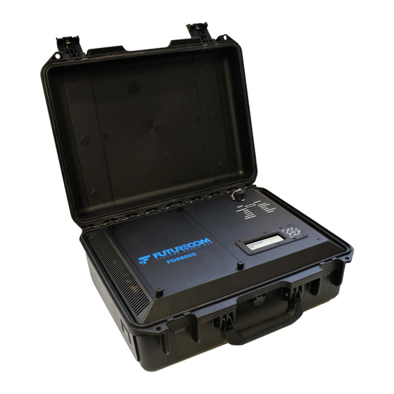
Portable digital repeater
Hide thumbs
Also See for PDR8000:
- Programming manual (98 pages) ,
- Manual (64 pages) ,
- Deployment manual (35 pages)

Subscribe to Our Youtube Channel
Related Manuals for Futurecom PDR8000


Summary of Contents for Futurecom PDR8000
- Page 1 Futurecom Systems Group, ULC ® PDR8000 Portable Digital Repeater Programming Guide Document: 8K088X04 Revision: R5.01 Date: 2022-08-25...
- Page 2 Document 8K088X04 R5.01 ® PDR8000 Portable Digital Repeater Programming Guide NOTES 2022-08-25 Page 2 of 86...
-
Page 3: Table Of Contents
RF Energy Exposure Compliance, Awareness and Control Information and Operational Instructions .. 16 PDR8000 Programming Basics ......................17 Installing and Uninstalling the Futurecom Repeater Configurator (FRC) ..........17 Using the Futurecom Repeater Configurator (FRC) Off-Line ..............18 Viewing PDR8000 Personality Files ....................... 18 Modifying PDR8000 Personality Files.................... - Page 4 PDR8000 Portable Digital Repeater Programming Guide Reading the PDR8000 Electronic Label ....................20 Reading from the PDR8000 (Uploading Data) ..................21 Writing to the PDR8000 (Downloading Data) ..................21 Writing Selected Changes to the PDR8000 ................... 22 Futurecom Repeater Configurator (FRC) Icons ..................23 PDR8000 Programming Guidelines ....................
- Page 5 Document 8K088X04 R5.01 ® PDR8000 Portable Digital Repeater Programming Guide PDR8000 operation with Booster Pack ....................73 PDR8000 Specifications ........................77 Troubleshooting ..........................80 Error & Warning Codes ........................81 Glossary............................83 Contact Information ......................... 85 2022-08-25 Page 5 of 86...
-
Page 6: Manual Revisions
Changed Tweaker references to Futurecom Repeater Configurator (FRC), documentation updates R4.03 2020-10-27 Added note about Rackmount to Booster Pack section R5.00 2021-11-08 Updates for DFSI and Rackmount PDR8000. R5.01 2022-08-25 Add Windows 11 as a supported OS 2022-08-25 Page 6 of 86... - Page 7 Document 8K088X04 R5.01 ® PDR8000 Portable Digital Repeater Programming Guide The list of Firmware given below is the minimum requirement for PDR8000 operation described in this document: Repeater Module Firmware: 4C088X01 5.01 Repeater Module Boot Firmware: 4C088X02 5.00 Transceiver DSP: 4C083X03 1.18 Baseband DSP: 4C083X04 1.54...
-
Page 8: Computer Software Copyrights
Futurecom. The purchase of Futurecom products shall not be deemed to grant either directly or by implication, estoppels, or otherwise, any license under the copyrights, patents, or patent applications of Futurecom, except for the normal non-exclusive license to use that arises by operation of law in the sale of a product. -
Page 9: Publicly Available Software List
Document 8K088X04 R5.01 ® PDR8000 Portable Digital Repeater Programming Guide The Futurecom Repeater Configurator provided by Futurecom Systems Group ULC includes the following Publicly Available Software. UBLICLY VAILABLE OFTWARE Name: MFC Grid Control Version: 2.24 Modified: Software Site: http://www.codeproject.com/KB/miscctrl/gridctrl.aspx Source Code: No Source Code Distribution Obligations. The Source Code may be obtained from the original Software Site. -
Page 10: Publicly Available Software - Common Licenses
Document 8K088X04 R5.01 ® PDR8000 Portable Digital Repeater Programming Guide – C UBLICLY VAILABLE OFTWARE OMMON ICENSES The Code Project Open License (CPOL) 1.02 Preamble This License governs Your use of the Work. This License is intended to allow developers to use the Source Code and Executable Files provided as part of the Work in any application in any form. - Page 11 Document 8K088X04 R5.01 ® PDR8000 Portable Digital Repeater Programming Guide You may use the standard version of the Source Code or Executable Files in Your own applications. You may apply bug fixes, portability fixes and other modifications obtained from the Public Domain or from the Author.
- Page 12 Document 8K088X04 R5.01 ® PDR8000 Portable Digital Repeater Programming Guide INCIDENTAL, CONSEQUENTIAL, PUNITIVE OR EXEMPLARY DAMAGES ARISING OUT OF THIS LICENSE OR THE USE OF THE WORK OR OTHERWISE, EVEN IF THE AUTHOR OR THE PUBLISHER HAS BEEN ADVISED OF THE POSSIBILITY OF SUCH DAMAGES.
-
Page 13: Codeguru License
However, no responsibility is assumed for inaccuracies. Futurecom Systems Group, ULC. reserves the right to make changes to any products herein to improve reliability, function or design. Futurecom does not assume any liability arising out of the application or use of any product or circuit described herein. -
Page 14: Declaration Of Conformity
However, there is no guarantee that interference will not occur in a particular installation. Changes or modifications not expressly approved by Futurecom Systems Group, ULC. could void the User’s authority to operate the equipment. MPORTANT... -
Page 15: Déclaration De Conformité
Pour assurer la conformité, le fonctionnement à une distance moins élevée n’est pas autorisé. Futurecom demande à l’opérateur du répéteur P25 DVRS de satisfaire aux exigences de la FCC / ISED en matière d’exposition à l’énergie RF. La distance minimale entre toutes les personnes possibles et une antenne omnidirectionnelle doit respecter les indications de la Brochure Sécurité... -
Page 16: Rf Energy Exposure Compliance, Awareness And Control Information And Operational Instructions
RF energy above the FCC exposure limit for bystanders (general population). It is the responsibility of the PDR8000 operator to ensure MPE limits are observed at all times during transmissions. The PDR8000 operator must ensure at all times that no person comes within MPE distance from the antenna. -
Page 17: Pdr8000 Programming Basics
To uninstall Tweaker – Control Panel → Add and Remove Programs → PDR_Tweaker → Remove. To uninstall the Futurecom Repeater Configurator (FRC) – Control Panel → Add and Remove Programs, → PDR8000 Futurecom Repeater Configurator (FRC) → Remove. To install the Futurecom Repeater Configurator (FRC), download the application from the Futurecom website into the desired location on your PC. -
Page 18: Using The Futurecom Repeater Configurator (Frc) Off-Line
ILES For saving Personality files, ensure the Futurecom Repeater Configurator (FRC) is On-Line. Power up the PDR8000. Connect the PDR8000 to the PC running the Futurecom Repeater Configurator (FRC). After editing the personality setting, the dpd file can be saved by selecting File → DPD Files (Templates) →... - Page 19 If the user selects ‘Custom’, a password is required to create the file. Note: After the PDR8000 is programmed as per the user’s requirements and the unit has been tested successfully with this template, it is recommended to save the template as dpd file on the computer for future use.
-
Page 20: Using The Futurecom Repeater Configurator (Frc) On-Line
PDR8000s during ‘cloning’. Note: An epr file contains the personality and calibration data of a specific PDR8000 unit. A dpd file contains the personality settings of a PDR8000 unit. Used for ‘cloning’. -
Page 21: Reading From The Pdr8000 (Uploading Data)
.dpd file name and location when prompted. If the user has an old dpd file created with R1.0 or R2.0 or R3.0, the Futurecom Repeater Configurator (FRC) upgrades this file to the current dpd format prior to applying it to the PDR8000. -
Page 22: Writing Selected Changes To The Pdr8000
EEprom screen which offers the options of saving the changes to the PDR8000 and resetting the PDR8000. If the data changes contain errors, the EEprom icon is flashing red and the screens containing conflicting data will be marked with a red exclamation mark. In this case, the changes cannot be written to the PDR8000 EEPROM until the errors are eliminated. -
Page 23: Futurecom Repeater Configurator (Frc) Icons
UTURECOM EPEATER ONFIGURATOR CONS The Futurecom Repeater Configurator (FRC) window on the top of the menu tree (left-hand side) displays icons for quick access to some of the menu items. The icons and their functionality are described below. 2022-08-25 Page 23 of 86... - Page 24 Document 8K088X04 R5.01 ® PDR8000 Portable Digital Repeater Programming Guide The icons on the individual Futurecom Repeater Configurator (FRC) menu denote the following: 2022-08-25 Page 24 of 86...
-
Page 25: Pdr8000 Programming Guidelines
PDR8000 C ONFIGURATION EVICE ATE AND To set the PDR8000 date and time connect the PDR8000 to the PC. Click on the PDR menu of the Futurecom Repeater Configurator (FRC). From the dropdown list select ‘Set Device Date and Time’. 2022-08-25... - Page 26 Get Date and Time HH:MM: SS Clicking on this button will get the current The user can from PDR Date, Time and Time Zone information change it manually from the PDR8000 connected to the PC. 2022-08-25 Page 26 of 86...
-
Page 27: Frequency Band Configuration
– Set 1, Set 2 and Set 3, which can be either Narrowband (12.5 kHz / 1.5 kHz) or Wideband (25 kHz / 3 kHz) or NPSPAC (25 kHz / 4kHz). Ensure the correct spacing (Set 1, Set 2, or Set 3) is selected to match the portable radio programming on each PDR8000 channel – see “Channel Configuration Deployment x”... - Page 28 PDR8000. in parentheses is the factory default. Channel-0 Base Indicates the lowest frequency for This field is read only. The value Frequency this PDR8000- either transmit or in parentheses is the factory receive. default. 2022-08-25 Page 28 of 86...
- Page 29 Rx Synthesizer 2.5000 kHz* Frequency step size used by the The value in parentheses shown Frequency Step receive synthesizer. in the Futurecom Repeater 5.0000 kHz* Configurator (FRC) window is the factory default. 6.2500 kHz * valid for VHF only Tx Synthesizer...
-
Page 30: Personality Information
Document 8K088X04 R5.01 ® PDR8000 Portable Digital Repeater Programming Guide ERSONALITY NFORMATION Field Name Options / Description Notes Units 2 digits Indicates the day for the date of programming for this personality template. MONTH 2 digits Indicates the month for the date of programming for this personality template. -
Page 31: Hardware/Software Information
Document 8K088X04 R5.01 ® PDR8000 Portable Digital Repeater Programming Guide ARDWARE OFTWARE NFORMATION This screen is for information purposes only and displays information relating to the Repeater Module and the IF Module: serial number, part numbers, revision/version numbers and release dates. -
Page 32: Common Settings
Document 8K088X04 R5.01 ® PDR8000 Portable Digital Repeater Programming Guide OMMON ETTINGS This Menu screen is used for enabling or disabling the Deployment profile capability, configuring Deployments, setting password and selecting the display unit menu. It will also indicate if the V.24 or DFSI Wireline operation and Deployment Profile capability options installed. - Page 33 (Rackmount PDR8000 only) Power up on Last Enabled/Disabled When enabled, the When enabled, then the PDR8000 powers up on the channel within the Deployment last active Deployment deployment profile that is Profile. When Disabled the active upon power up is...
- Page 34 Allows the user to Opens a new window. enable/disable If ‘Deployment Profile deployments as per the Capability’ is enabled. PDR8000 Order. Any Deployment can be copied Refer section 2.6.4.1.1 of to any other Deployment. the PDR8000 Deployments can be reset Programming Guide to factory default.
- Page 35 Document 8K088X04 R5.01 ® PDR8000 Portable Digital Repeater Programming Guide Field Name Options / Units Description Notes User Language English User can select preferred language on the display. French Spanish Display Settings Upon clicking opens Resets Display Contrast up menu to reset and Brightness.
-
Page 36: Configure Deployments
PDR8000 Portable Digital Repeater Programming Guide Configure Deployments Enables the user to configure Deployments as per the Order placed for PDR8000. Note: The order of the deployments can be rearranged by dragging and dropping the deployments in the list of deployments. - Page 37 Field Name Options / Description Notes Units Deployments order on the List of Deployments and theirs Status Enabled or Disabled PDR8000 Display Deployment Information Deployment name – up to 16 max Name characters Enabled Deployment enabled when checkbox is Deployment status...
- Page 38 Document 8K088X04 R5.01 ® PDR8000 Portable Digital Repeater Programming Guide Selecting “Yes” will apply the changes to the Deployment configuration. Keypad Password Set password to lock the PDR8000 keypad. Field Name Range Description Notes Password Select the sequence of the arrow...
-
Page 39: Deployment Data Configuration
RF frequencies. By utilizing the ten possible Deployment Profiles, PDR8000 can be ready to “pick up and go” for a large number of common use case scenarios. The PDR8000 can be configured to power-up to a specific Deployment Profile or can power to the “last active”... -
Page 40: General Configuration
ONFIGURATION The Deployment data is configured in the ‘General Configuration’ menu. The Deployments can be Enabled or Disabled. The PDR8000 Hardware platform can be specified. Wireline or RT/RT mode is selected in this menu. Many other general parameters pertaining to the specific deployment can be programmed. - Page 41 This field is enabled when V.24 Tx Clock. This is needed for Wireline Interface is set to Clock External PDR8000 cross connect (RT/RT) V.24. and some modems Internal: The PDR8000 provides the clock. This choice is typically selected when the radio is connected directly to an infrastructure device.
- Page 42 Fallback Determination Time expires, then the PDR8000 does automatically activate its local repeat capabilities. Fallback 180ms Amount of time the PDR8000 waits This timer is used when the Determination for an outbound payload from the Fallback In-Cabinet Repeat is 50-10000ms...
- Page 43 Enabled Startup Channel 1-64 Specifies the channel to which This field is ignored when PDR8000 is set after a reset. Startup on Last Active Channel field is set to Enabled. BSI Interval 1-60 minutes...
- Page 44 Document 8K088X04 R5.01 ® PDR8000 Portable Digital Repeater Programming Guide Repeater P25 Preamble 7.50-265.00 ms Specifies the duration of bit sync Length preamble packets that are sent at 40 ms the beginning of all ASTRO transmissions. RSSI RSSI Off 2-20dB Sets the Received Signal Strength Typically set to 5dB.
- Page 45 Enable/Disable Enables or Disables the Fast AFC Default setting is Enable. Set disable during calibration. Side LED Enable/Disable Switches the LED above the PDR8000 Suitcase only. PDR8000 ‘RF OUT’ port on the side panel ON/OFF. 2022-08-25 Page 45 of 86...
-
Page 46: Channel Configuration
HANNEL ONFIGURATION The V.24 wireline interface to PDR8000 is a full-duplex link, able to send and receive information at the same time. However, there are different configurations for the RF aspect of a PDR8000 that govern whether the PDR8000 can both Transmit and Receive on the RF channel at the same time (full-duplex), or whether only one side of the RF channel is serviced at once (half-duplex). - Page 47 PDR8000 display. Channel Type Analog Determines the PDR8000 Analog & Mixed Channels work with PDR8000 in Repeater mode Channel type. Digital only. Mixed Determines the PDR8000 mode of - Repeater Mode: only Full Duplex Channel Mode F.Duplex...
- Page 48 Tx Pwr (Watts) 1-20 Watts Specifies the transmit power at Read only the Power Amplifier output of the 1.0 Watts PDR8000 in (W) NAC Table Index 1-64 Identifies which of the 64 possible Access Code Tables applies to the current channel.
- Page 49 -50 to -127dBm Received Signal Strength (dBm) Indicator Threshold specifies the -100dBm signal level at the input of the PDR8000 receiver, required to validate the signal 0-2550 seconds, Wireline Time Out Timer specifies Any value entered that is not an W.T.O.T. (sec)
- Page 50 PDR8000 will notify the infrastructure (wireline) every of any co-channel users. 5 seconds. The PDR8000 will not transmit data once it receives this message. When co-channel Enabled: PDR8000 monitors the activity stops, the PDR8000 will...
-
Page 51: Channel - Access Code Table Astro Nac Assignments
NACs. These behaviors are captured in NAC Code Table. Each configured channel in the PDR8000 can point to one of the configured Access Code Tables. Each Access Code Table can be used to define NAC operation for a specific channel or may capture behavior shared by multiple channels. - Page 52 Document 8K088X04 R5.01 ® PDR8000 Portable Digital Repeater Programming Guide Figure 1: NAC Table See below for description of the fields in NAC table. 2022-08-25 Page 52 of 86...
- Page 53 Decrements Access Code Table by 1 < Next Tbl 1-64 Goes to the next Access Channel Table Channels Using Comma separated List of PDR8000 channel number(s) that use This field is read This Table: list of numbers, 1-64 current access code table. only...
- Page 54 Document 8K088X04 R5.01 ® PDR8000 Portable Digital Repeater Programming Guide Field Name Options / Units Description Notes Tx NAC Selected Specifies how Tx NAC is selected for A DFSI- by Last Received transmitting the infrastructure audios. connected console may Rx NAC...
- Page 55 Document 8K088X04 R5.01 ® PDR8000 Portable Digital Repeater Programming Guide Field Name Options / Units Description Notes Multi-NAC Table Maximum 8 pairs Defines up to eight Rx and Tx Network If Rx NAC Access Code pairs for the specified Access...
-
Page 56: Analog Code Table
PLs/DPLs. These behaviors are captured in Analog Code Tables. Each configured channel in the PDR8000 can point to one of the configured Analog Code tables. Each table can be used to define PL/DPL operation for a specific channel or may capture behavior shared by multiple channels. - Page 57 Rx PL/DPL code entries found in any enabled row of the table. PDR8000’s Rx STE in that row of the table should be set to match the Tx STE sent by the subscriber units.
- Page 58 Document 8K088X04 R5.01 ® PDR8000 Portable Digital Repeater Programming Guide Figure 2: PL/DPL Code Table See below for description of the fields in the PL/DPL Code Table. 2022-08-25 Page 58 of 86...
- Page 59 Decrements Analog Code Table by 1 < Next Tbl 1-64 Goes to the next Analog Code Table Channels Using Comma separated List of PDR8000 channel number(s) that use This field is read This Table: list of numbers, 1-64 current Analog Code Table. only.
- Page 60 Document 8K088X04 R5.01 ® PDR8000 Portable Digital Repeater Programming Guide Field Name Options / Units Description Notes Tx PL/DPL Specifies how Tx PL/DPL is selected for Selected by Last transmitting the infrastructure audios. Received Rx Enabled: When the Tx PL/DPL Selected by...
- Page 61 Document 8K088X04 R5.01 ® PDR8000 Portable Digital Repeater Programming Guide Field Name Options / Units Description Notes Tx PL/DPL 67.0-254.1 Defines transmit PL/DPL DPL: d-023-d-0754 Tx PL/DPL STE deg/DPL Analog PSU PL/DPL STE-Squelch Tail Elimination – must be programmed to match...
-
Page 62: Service
Portable Digital Repeater Programming Guide ERVICE The Futurecom Repeater Configurator (FRC)’s Monitoring Screen is provided to assist the field technician with PDR8000 setup and troubleshooting. The Monitoring screen provides real time indication of the RSSI level, RF Power, NAC, PL/DPL detection, BER measurement & display of Signal quality as described below. -
Page 63: Monitoring
Normal Specifies the current mode of User configurable. Mode operation Service When PDR8000 is operating in Normal: PDR8000 is Service mode, transmissions are operating as programmed initiated only by using the front panel PTT button or the PTT configurable Service: PDR8000 is field in this window. - Page 64 1-64 Identifies the current channel of the 16 possible channels Toggle Gate Set Up/ Toggles the Repeater Gate PDR8000 must have the V.24 option. Status between ‘Set up’ and Status Knocked Down ‘Knocked Down’ if Wireline Interface is selected as’V.24’.
- Page 65 Transmitter Activity Idle Specifies the Transmitter Activity Active Tx Source Inbound Displays if the PDR8000 is receiving from the Subscriber Outbound or transmitting on V.24 Link. Tx NAC Displays the NAC transmitted to the Subscriber Tx PL/DPL Displays the PL/DPL received...
- Page 66 RSSI Received signal strength in Read only RSSI Received signal strength in Read only RF Power RF Power PDR8000 transmitting RF Read only power in dBm RF Power PDR8000 transmitting RF Read only power in W Squelch ON dB SINAD Sets the Squelch ON Affects Analog Mode only.
- Page 67 Reverse DFSI* Shows the IP Address of the IPv4 address for the DFSI host. Host IP Address 0.0.0.0 Provided to PDR8000 by the host DFSI Host when PDR8000 wireline interface is set to DFSI. Host Control Port Max 65535 UDP Port at which the fixed...
-
Page 68: Status Report
Read Only Temperature temperature. Note: Fields in Booster Pack group are populated only when connected to PDR8000. Not applicable to Rackmount PDR8000 with 50W PA option. Note: In the Options/Units column, the option in bold text indicates the default value. -
Page 69: Status Log
Portable Digital Repeater Programming Guide TATUS Field Name Description Notes Options / Units Get Status Gets the PDR8000 current Status Log Save Status Saves the Status Log as text file Clear All Clears the contents EEPROM L TATUS Field Name... -
Page 70: Booster Pack
Portable Digital Repeater Programming Guide Booster Pack For those agencies using Mobile Radios in their system, the PDR8000 Portable Digital Repeater Booster Pack can assist them with additional output from their 20Watt PDR8000. The Booster Pack is available in VHF, UHF 380-430, UHF 450-470, 700 MHz and 800 MHz bands. It is housed in a separate suitcase, which is the same size of the PDR8000 suitcase. -
Page 71: Booster Pack Specifications
Document 8K088X04 R5.01 ® PDR8000 Portable Digital Repeater Programming Guide OOSTER PECIFICATIONS General Specifications 488 mm (19.2”) x 386 mm (15.2”) x 185 mm (7.3”) Dimensions: Width / Height / Depth Weight 23.2 lbs. / 10.5kg AC Supply Voltage 100V AC to 240V AC, 47Hz to 63Hz AC Current at 120V AC 4.0A... -
Page 72: Pdr8000 And Booster Pack Hardware Configurations
The figures below show the interconnection between the PDR8000 and the Booster pack. These figures are also screened on the back of the removable top panel inside the PDR8000. Figure 3 - Internal Duplexer and Booster Pack Hardware Configuration... -
Page 73: Pdr8000 Operation With Booster Pack
“Channel Setup’. The PDR8000 can transmit max 20W (43 dBm) output power at it’s Tx Port. When the Booster pack is connected to the PDR8000 as shown in Fig 3 & Fig 4, the PDR8000 automatically detects the presence of the Booster pack and adjusts it’s Output Tx Power on the selected channel to 1.75W (32.5 dBm). - Page 74 In the Monitoring window, select the PDR8000 operating mode ‘Service’, PTT: PTT ON. Observe the RF Power in the Monitoring Window. The Booster pack is still not connected to the PDR8000. The Booster pack State is OFF. • The Booster Pack is now connected to the PDR8000 and powered up.
- Page 75 • Select the PDR8000 Operating mode as ‘Service’ and PTT: PTT ON. With the Booster connected and Active. The RF power of the PDR8000 drops down between 1-2 W (1.75 W) from the programmed 20W as displayed. The Power measured at RF output of the Amplifier of the Booster pack will be 50W.
- Page 76 Document 8K088X04 R5.01 ® PDR8000 Portable Digital Repeater Programming Guide 2022-08-25 Page 76 of 86...
-
Page 77: Pdr8000 Specifications
V.24 RJ-45 Type, 17-111574, with Dustcap RJ-45 Type, 17-111574, with Dustcap Stainless steel stud, 0.5” long with 10-32 thread Ground Internal Connector Computer Interface USB (type B) Connector was EGG.1K.306.CLL prior to PDR8000 Release 4 2022-08-25 Page 77 of 86... - Page 78 Document 8K088X04 R5.01 ® PDR8000 Portable Digital Repeater Programming Guide Channel Spacing Digital: 12.5kHz programmable Analog: 12.5 kHz or 25 kHz programmable Number of Channels IEC IP Rating During Operation and IP65 Storage (Closed Case) Military Standards Compliance MIL-STD-810G High Temperature 501.6...
- Page 79 FM Hum and Noise 12.5kHz 37dB Connector was EGG.1K.306.CLL prior to PDR8000 Release 4 Specifications are typical and subject to change without notice. Futurecom Systems Group, ULC does not accept liability for any error or omission in this document. 2022-08-25...
-
Page 80: Troubleshooting
Errors/Warnings may be caused due to any of the following reasons: • Improper PDR8000 Programming. • PDR8000 Firmware upgrade is improperly done. (Make sure the PDR8000 is on the current released Firmware available on the Futurecom website.) PDR PTT RESET General Status LEDs... -
Page 81: Error & Warning Codes
Document 8K088X04 R5.01 ® PDR8000 Portable Digital Repeater Programming Guide Error & Warning Codes The following Error codes may be displayed on the PDR8000 display. Major Error Codes 80000000 Incompatible BaseBand DSP code loaded 40000000 Incompatible Transceiver DSP code loaded... - Page 82 Bad main EEPROM map data Bad backup EEPROM map data EE map version mismatch Options mismatch RTC battery failed/time invalid PDR8000 fan control board failed RF Error Codes 8000 Baseband DSP alarm (failed to load/start) 4000 Transceiver DSP alarm (failed to load/start)
-
Page 83: Glossary
Fixed Network Equipment – Trunking or Conventional System Infrastructure Inbound Call A Call transmitted by Local PSU and received by the PDR8000 Network Access Code – used in P25 mode for validation of P25 radio communications, similar to the use of PL/DPL in analog mode. - Page 84 PDR8000 Programming Software Application Configurator (FRC) V.24 A digital link better described as a physical V.24 link with HDLC (High-level Data Link Control). Used to connect PDR8000 to other infrastructure elements (e.g., CCGW, DIU, comparator) 2022-08-25 Page 84 of 86...
-
Page 85: Contact Information
Document 8K088X04 R5.01 ® PDR8000 Portable Digital Repeater Programming Guide Contact Information Technical Support 905-660-5548 support@futurecom.com Orders Please contact Motorola / Drop Ship Return Authorizations 1-800-701-9180 Head Office and Manufacturing 3277 Langstaff Rd Concord, Ontario L4K 5P8 Canada 905-660-5548 www.futurecom.com... - Page 86 Subscribe to our newsletter if you want to be informed about new releases and updates. Please visit http://futurecom.com/support/newsletter/ Futurecom Systems Group, ULC. 3277 Langstaff Rd Concord, Ontario L4K 5P8 Canada 1-800-701-9180 © Futurecom Systems Group, ULC 2022 2022-08-25 Page 86 of 86...
Need help?
Do you have a question about the PDR8000 and is the answer not in the manual?
Questions and answers